
Table Of Contents
Upgrading from a Previous Version
Installing PIX Firewall Upgrade Kits
Installing PIX Firewall
To install and configure PIX Firewall you need an ASCII terminal or a computer with serial communications software installed and running. The computer can be a Windows workstation, Macintosh system, or UNIX system. (However, using a Macintosh requires a special cable that you must obtain from an Apple computer vendor.)
Install PIX Firewall as follows:
Step 1
Read the Cisco PIX Firewall Release Notes completely.
Step 2
Unpack PIX Firewall and place it in a convenient location.
Step 3
Connect the power cord to PIX Firewall and plug it in.
Step 4
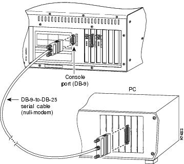
Connect the null modem serial cable to the PIX Firewall DB-9 console port and connect the PIX Firewall serial console cable DB-25 connector to your ASCII terminal or computer as shown in . Use the gender adapter if necessary.
Figure 2-1 Connecting a Serial Cable to the Console Port and to a PC
Step 5
Configure the serial port in your computer or terminal with these settings: 9600 baud, 8 data bits, no parity, and 1 stop bit; that is, set 9600, 8-N-1. Ensure your terminal communications software is running on the console.
Step 6
If you purchased the optional failover cable, prepare the secondary PIX Firewall as described in the previous steps and attach the failover cable between the two units. Refer to Installing the Failover Connector Assembly and Cable (Document Number 78-3749-01) supplied with the failover cable option for more information about upgrading an existing PIX Firewall unit to accept the failover cable.
Attach the end of the cable labeled "0" to the unit that initially will be the primary unit. Attach the other end to the secondary unit. In the steps that follow, assume that the procedure for a single PIX Firewall applies to both PIX Firewall units. shows how to connect the failover cable between two PIX Firewall units.
Figure 2-2 Connecting a Failover Cable Between Two PIX Firewall Units
Note
If you are upgrading from a previous PIX Firewall version, refer now to the next section, "Upgrading from a Previous Version."
Step 7
Otherwise, turn on the power switch as shown in .
Figure 2-3 Open Front Access Panel to Power On Unit
Because PIX Firewall ships with its software already in flash memory, it boots without the need for you to insert the system diskette.
Step 8
As PIX Firewall boots, messages appear on your computer or terminal such as the following:
PIX Bios V2.7Booting Floppy...................................Execing flopFloppy loader version 1.04Flash=i28F020.Floppy -> FlashReading floppy image........................Using flash configErasing flash...Burning image into flash...Saving config...8MB RAMFlash=i28F020Ethernet=3c595 MAC=00a0.2435.ef7d ports=rj,feEthernet=3c595 MAC=00a0.2451.80c8 ports=rj,feCA9568 Encryption @ 0x3a0P r i v a t e I n t e r n e t e X c h a n g e-----------------------------------------------------------------------ppppppp iiiii xxx xxxp p i x xp p i x xp p i x xp p i xxp p i xxppppppp i x xp i x xp i x xp iiiii xxx xxx-----------------------------------------------------------------------(c) Cisco Systems, Inc.PIX Version 3.nMaximum Connections: 16384Copyright (c) 1996 by Cisco Systems, Inc.Restricted Rights LegendUse, duplication, or disclosure by the Government issubject to restrictions as set forth in subparagraph(c) of the Commercial Computer Software - RestrictedRights clause at FAR sec. 52.227-19 and subparagraph(c) (1) (ii) of the Rights in Technical Data and ComputerSoftware clause at DFARS sec. 252.227-7013.Cisco Systems, Inc.170 West Tasman DriveSan Jose, California 95134-1706pixfirewall>Step 9
At the rear of the unit, connect the network cable from the hub containing your internal network to the Ethernet or Token-Ring adapter on the PIX Firewall labeled "Inside" as shown in .
Figure 2-4 Connect Network Interface Cables to Rear of Unit
Step 10
At the rear of the unit, connect the network cable for the external, Internet-connected network to the Ethernet or Token-Ring adapter on the PIX Firewall labeled "Outside."
The installation is now complete. You can now test the connectivity of your PIX Firewall on your network.
You are now ready to configure PIX Firewall as described in the chapter.
Upgrading from a Previous Version
To upgrade from a previous version of PIX Firewall, follow these steps:
Step 1
Read the Cisco PIX Firewall Release Notes completely.
Step 2
Save the current contents of flash memory to diskette. If you are using PIX Firewall version 2 or earlier, use the save -f command. If you are upgrading from version 3, use the write floppy command.
Step 3
Remove the configuration diskette from the drive and insert the upgrade floppy disk in the drive.
Step 4
If you are using version 2 or earlier software, enter the reboot command. If you are using version 3 or later, access configuration mode and enter the reload command. An alternative to either version is to simply power off the unit, wait 10 seconds, and power the unit back on.
Step 5
When the unit reboots the startup messages appear.
Step 6
You are now ready to configure the PIX Firewall.
Installing PIX Firewall Upgrade Kits
If you purchased one or more optional PIX Firewall upgrade kits or spares, install each with the instructions provided before continuing.
Note
Before installing a PIX Firewall upgrade kit or spare, remove the power cable from your PIX Firewall unit.

 Feedback


