Configuring Network-based IDS and IPS Devices
Available Languages
Table Of Contents
Configuring Network-based IDS and IPS Devices
Configure Sensors Running IDS 3.1
Add and Configure a Cisco IDS 3.1 Device in MARS
Cisco IDS 4.0, IPS 5.x, and IPS 6.x Sensors
Enable the Access Protocol on the Sensor
Enable the Correct Signatures and Actions
Add and Configure a Cisco IDS or IPS Device in MARS
Specify the Monitored Networks for Cisco IPS or IDS Device Imported from a Seed File
View Detailed Event Data for Cisco IPS Devices
Verify that MARS Pulls Events from a Cisco IPS Device
IPS Signature Dynamic Update Settings
Troubleshooting IPS Signature Dynamic Updates
File Naming, Encoding, and Structure Guidelines for the Custom Signature Map File
Example Custom Signature Map Files
Import Custom Signature Maps into MARS
Enable SDEE on the Cisco IOS Device with an IPS Module
Add an IPS Module to a Cisco Switch or Cisco ASA
IBM Proventia Management/ISS SiteProtector to Define Global Event Policies
IBM Proventia Management/ISS SiteProtector 2.0 as A Reporting Device
Configure SiteProtector to Forward SNMP Notifications to MARS
Add and Configure a SiteProtector Device in MARS
Configure ISS RealSecure to Send SNMP Traps to MARS
Add an ISS RealSecure Device as a NIDS
Add an ISS RealSecure Device as a HIDS
Extracting Intruvert Sensor Information from the IntruShield Manager
Configure IntruShield Version 1.5 to Send SNMP traps to MARS
Configure IntruShield Version 1.8 to Send SNMP Traps to MARS
Add and Configure an IntruShield Manager and its Sensors in MARS
Add the IntruShield Manager Host to MARS
Add IntruShield Sensors Manually
Add IntruShield Sensors Using a Seed File
MARS Expectations of the Snort Syslog Format
Configure Snort to Send Syslogs to MARS
Symantec ManHunt Side Configuration
Add Configuration Information for Symantec ManHunt 3.x
NetScreen IDP Device and Server Support
Bootstrap a NetScreen Security Manager
Bootstrap a NetScreen IDP Management Server
Add NetScreen Server or Sensor to MARS
Configure the syslog on the UNIX host
Add Configuration Information for the Enterasys Dragon
Configuring Network-based IDS and IPS Devices
Revised: November 30, 2007Network intrusion detection and intrusion preventions systems are a critical source for identifying active attacks to MARS.
This chapter explains how to bootstrap and add the following network-based IDS and IPS devices to MARS:
•
Cisco IDS 4.0, IPS 5.x, and IPS 6.x Sensors
•
IPS Signature Dynamic Update Settings
•
IBM Proventia Management/ISS SiteProtector to Define Global Event Policies
•
IBM Proventia Management/ISS SiteProtector 2.0 as A Reporting Device
•
NetScreen IDP Device and Server Support
Cisco IDS 3.1 Sensors
Before you add the Cisco IDS 3.1 device, make sure that you have configured the Cisco IDS device for the MARS to retrieve the device configuration. The device configuration would be used for mapping of the logs received by MARS.
When configuring the IDS device to send logs to the MARS, you must use the exact name of the MARS Appliance. To determine the name of the appliance, select Admin > System Setup > Configuration Information and review the value in the Name field.
Configure Sensors Running IDS 3.1
Step 1
Log in to the Cisco IDS device.
Step 2
Change to directory that has all the configurations files that need to be edited:
cd /usr/nr/etcStep 3
You need to edit 4 files (organizations, hosts, routes and destinations) that are in this directory.
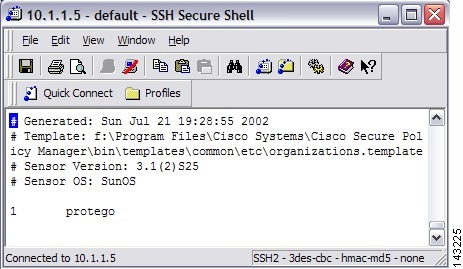
In the organizations file add a line indicating your organization name or grouping;
e.g., 1 protegowhere 1 is the item number followed by the organization name protego. If there is already item in this file, simply increase the item number (has to be unique).
Figure 7-1 Add MARS Information to Cisco IDS 3.1 Organizations File
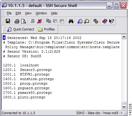
In the hosts file add a line indicating your MARS appliances' name associated to the organization that was previously added in the organizations file;
e.g., 2001.1 pnmars.protegowhere 2001.1 is a unique item number followed by the MARS appliances' name and organization name protego. If there is already items in this file, simply increase the item number (has to be unique).
Figure 7-2 Add MARS Information to Cisco IDS 3.1 Hosts File
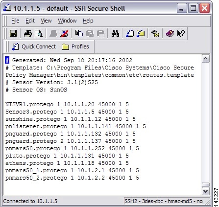
In the routes file add a line indicating your MARS appliances' name and its IP address;
e.g., pnmars.protego 1 10.1.1.10 45000 1 5where pnmars.protego is the MARS's name (with organizations' name) followed by 1 then the MARS appliances' IP address.
The 45000 is the port number that the IDS will use to send its logs to MARS. Add a 1 follows by a 5 at the end of this line (these numbers are not used by MARS).
Figure 7-3 Add MARS Information to Cisco IDS 3.1 Routes File
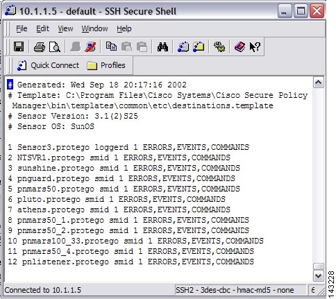
In the destinations file add a line indicating your MARS appliances' name (as defined in the routes file) the client process that the appliance is using to listen for events from the sensor (in this case smid), and the list of log types you want sent to the appliance as a comma separated list:
e.g., pnmars.protego smid ERRORS, EVENTS, COMMANDSwhere
pnmars.protegois the MARS's name (with organizations' name) followed by smid and the list of log types that the loggerd daemon will publish to the appliance.Figure 7-4 Add MARS Information to Cisco IDS 3.1 Destinations File
Step 4
Once you've edited these four files (organizations, hosts, routes, and destinations), reboot the sensor using the following commands:
a.
nrstop
b.
nstart
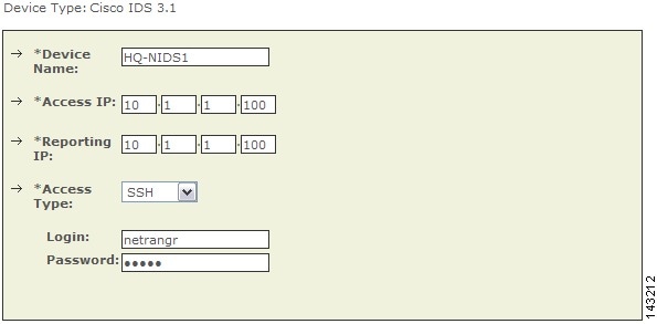
Add and Configure a Cisco IDS 3.1 Device in MARS
To add and configure a Cisco IDS device in MARS, follow these steps:
Step 1
Click Admin > System Setup > Security and Monitor Devices > Add.
Step 2
Select Cisco IDS 3.1 from the Device Type list.
Step 3
Enter the hostname of the sensor in the Device Name field.
The Device Name value must be identical to the configured sensor name.
Step 4
Enter the administrative IP address in the Access IP field.
Step 5
Enter the administrative IP address in the Reporting IP field.
The Reporting IP address is the same address as the administrative IP address.
Step 6
Select either SSH or TELNET.
Step 7
Enter "netrangr" as the Login and its Password.
When adding a Cisco IDS 3.1 device, use the netrangr username or some other username that is not the root login for the sensor. Using the root login causes MARS to fail to parse the login prompt correctly, which in turn, cause the Test Connectivity to fail.
Figure 7-5 Configure Cisco IDS 3.1
Step 8
For attack path calculation and mitigation, add networks into the Monitored Networks field.
a.
Click the Select a Network or Define a Network radio button.
•
In the Select a Network list, click a network.
•
In the Define a Network field, enter its network IP and network mask information.
b.
Click Add to move the selected networks into the Monitored Networks field.
Step 9
(Optional) To discover the device settings, click Discover.
Step 10
Click Submit.
Cisco IDS 4.0, IPS 5.x, and IPS 6.x Sensors
Adding a Cisco IDS or IPS network sensor to MARS involves two parts:
2.
Add and Configure a Cisco IDS or IPS Device in MARS
3.
Verify that MARS Pulls Events from a Cisco IPS Device
The following topic supports Cisco IDS and IPS devices:
•
View Detailed Event Data for Cisco IPS Devices

Note
If you've imported your sensor definitions using the seed file format, as specified in Load Devices From the Seed File, page 2-25, you must define the networks monitored by the sensor.
Bootstrap the Sensor
Preparing a sensor to be monitored by MARS involves two steps:
•
Enable the Access Protocol on the Sensor
•
Enable the Correct Signatures and Actions
Enable the Access Protocol on the Sensor
The configuration of the sensor depends on the version of the software that is running on the sensor. The following topics identify the requirements of each version:
•
Cisco IPS 5.x and 6.x Software
Cisco IDS 4.x Software
For Cisco IDS 4.x devices, MARS pulls the logs using RDEP over SSL. Therefore, MARS must have HTTPS access to the sensor. To prepare the sensor, you must enable the HTTP server on the sensor, enable TLS to allow HTTPS access, and make sure that the IP address of MARS is defined as an allowed host, one that can access the sensor and pull events. If the sensors have been configured to allow access from limited hosts or subnets on the network, you can use the
accessList ipAddressip_address netmask command to enable this access.Cisco IPS 5.x and 6.x Software
For Cisco IPS 5.x and 6.x devices, MARS pulls the logs using SDEE over SSL. Therefore, MARS must have HTTPS access to the sensor. To prepare the sensor, you must enable the HTTP server on the sensor, enable TLS to allow HTTPS access, and make sure that the IP address of MARS is defined as an allowed host, one that can access the sensor and pull events. If the sensors have been configured to allow access from limited hosts or subnets on the network, you can use the
access-listip_address/netmask command to enable this access.Enable the Correct Signatures and Actions
If the signature actions are correctly configured, MARS can display the trigger packet information for the first event that fires a signature on a Cisco IDS or IPS device. MARS is also able to pull the IP log data from Cisco IDS and IPS devices, however, this operation is system intensive. Therefore, you should select the set of signatures that generate IP log data carefully.
When configuring the active signatures on a Cisco IDS or IPS device, you must specify the alert action and the action that generates the desired data:
•
To view trigger packets, you must enable the "produce-verbose-alert" action.
•
To view IP logs, you must enable the alert or "produce-verbose-alert" action and the "log-pair-packets" action.

CautionConfiguring IP logging and verbose alerts on the sensor is system intensive and does affect the performance of your sensor. In addition, it affects the performance of your MARS Appliance. Because of these effects, you be cautious in configuring signatures to generate IP logs.
Add and Configure a Cisco IDS or IPS Device in MARS
To add and configure a Cisco IDS or IPS device in MARS, follow these steps:
Step 1
Click Admin > System Setup > Security and Monitor Devices > Add.
Step 2
Do one of the following:
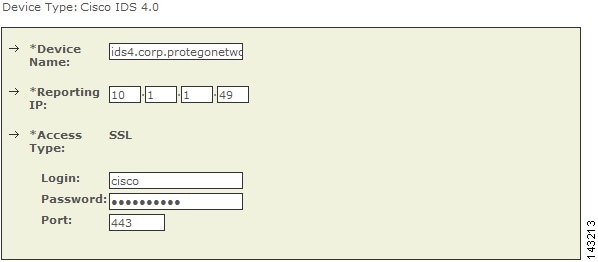
•
Select Cisco IDS 4.0 from the Device Type list.
Figure 7-6 Configure Cisco IDS 4.0
•
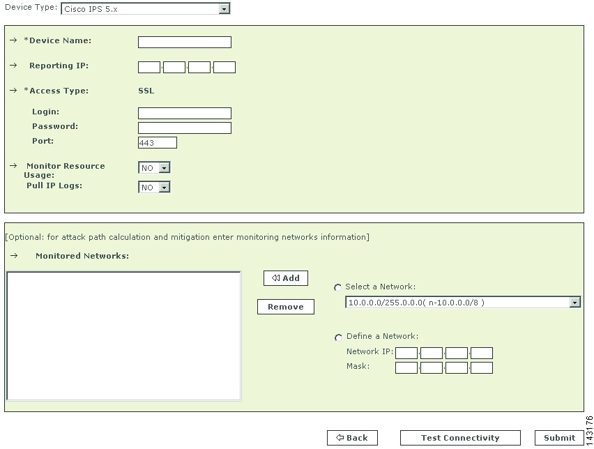
Select Cisco IPS 5.x or Cisco IPS 6.x from the Device Type list.
Figure 7-7 Configure Cisco IPS 5.x and 6.x
Step 3
Enter the hostname of the sensor in the Device Name field.
The Device Name value must be identical to the configured sensor name.
Step 4
Enter the administrative IP address in the Access IP field.
Step 5
Enter the administrative IP address in the Reporting IP field.
The Reporting IP address is the same address as the administrative IP address.
Step 6
In the Login field, enter the username associated with the administrative account that will be used to access the reporting device.
Step 7
In the Password field, enter the password associated with the username specified in the Login field.
Step 8
In the Port field, enter the TCP port on which the webserver running on the sensor listens. The default HTTPS port is 443.

Note
While it is possible to configure HTTP only, MARS requires HTTPS.
Step 9
To pull the IP logs from the sensor, select Yes in the Pull IP Logs box.
Step 10
For attack path calculation and mitigation, specify the networks being monitored by the sensor. Do one of the following:
To manually define the networks, select the Define a Network radio button.
a.
Enter the network address in the Network IP field.
b.
Enter the corresponding network mask value in the Mask field.
c.
Click Add to move the specified network into the Monitored Networks field.
d.
Repeat as needed.
To select the networks that are attached to the device, click the Select a Network radio button.
a.
Select a network from in the Select a Network list.
b.
Click Add to move the selected network into the Monitored Networks field.
c.
Repeat as needed.
Step 11
To verify the configuration, click Test Connectivity.
Step 12
Click Submit.
Specify the Monitored Networks for Cisco IPS or IDS Device Imported from a Seed File
After you import a Cisco IPS or IDS device into MARS using a seed file, you must define the networks that are monitored by that sensor.
To define the networks monitored by a sensor, follow these steps:
Step 1
Click Admin > System Setup > Security and Monitor Devices.
Step 2
Select the check box next to the Cisco IPS or IDS device that was imported using a seed file. and click Edit.
Step 3
To specify the networks being monitored by the sensor, do one of the following:
To manually define the networks, select the Define a Network radio button.
a.
Enter the network address in the Network IP field.
b.
Enter the corresponding network mask value in the Mask field.
c.
Click Add to move the specified network into the Monitored Networks field.
d.
Repeat as needed.
To select the networks that are attached to the device, click the Select a Network radio button.
a.
Select a network from in the Select a Network list.
b.
Click Add to move the selected network into the Monitored Networks field.
c.
Repeat as needed.
Step 4
To save your changes, click Submit.
Step 5
To enable MARS to start sessionizing events from this module, click Activate.
View Detailed Event Data for Cisco IPS Devices
You can view the trigger packets and IP log data associated with incidents reported by Cisco IDS 4.x and Cisco IPS 5.x and 6.x devices, whether they are sensor appliances or modules. This information is useful when an in-depth understanding of the attack method is desired. MARS includes two event types that focus on the these two data types:
•
Trigger packet data. Identifies the data that was being transmitted on the network the instant an alarm was detected. You can use this information to help diagnose the nature of an attack. The trigger packet provides a single data packet—the data packet that caused the alarm to fire.
•
Packet data. Identifies the data that was being transmitted on the network the instant an alarm was detected. You can use this information to help diagnose the nature of an attack. Although the amount of data contained in an IP log varies based on sensor configuration, by default an IP log contains 30 seconds of packet data. To view this data, you must enable the Pull IP Logs option on the Cisco IPS device under Admin > System Setup > Security and Monitor Devices.

Note
MARS does not collect this data for Cisco IDS 3.x devices.
For the correct signature settings required to generate this data, see Enable the Correct Signatures and Actions.
If the IP log feature is enable for the reporting Cisco IPS device, these event types are combined as part of the incident data. You can view this data by drilling down in an incident, expanding the desired event type (either Packet Data or Trigger Packet Data), selecting an event, and clicking on the RAW Events for this Session icon under the Reporting Device column of that event. The source, destination, and other data displayed for these events matches that of the original alert. In addition, this data appears hexadecimal and binary format.

Note
The trigger packet and IP log data is stored using a base64-encoded format in the MARS database. Therefore, keyword search does not work on it if you just provide the search string.
Verify that MARS Pulls Events from a Cisco IPS Device

Note
If the Test Connectivity operation does not fail when configuring a Cisco IPS device in the MARS web interface, then communications are enabled. This task allows you to further verify the alerts are generated and pulled correctly.
It is common to create benign events on the network to verify the data flow. To verify the data flow between a Cisco IPS device and MARS, perform the following tasks:
1.
On the Cisco IPS device, enable and alert on the signatures 2000 and 2004. The signatures monitor ICMP messages (pings).
2.
Ping a device on the subnet on which the Cisco IPS device is listening. The events are generated and pulled by MARS.
3.
Verify that the events appear in the MARS web interface. You can perform a query using the Cisco IPS device.
4.
Once the dataflow is verified, you can disable the 2000 and 2004 signatures on the Cisco IPS device.
IPS Signature Dynamic Update Settings
In releases 6.0 and later, Cisco IPS support dynamic signature updates. Beginning in 4.3.1 and 5.3.1, MARS can discover the new signatures and correctly process and categorize received events that match those signatures. If this feature is not configured, the events appears as unknown event type in queries and reports, and MARS does not include these events in inspection rules. These updates provides event normalization and event group mapping, and they enable your MARS Appliance to parse Day Zero signatures from the IPS devices.
The downloaded update information is am XML file that contains the IPS signatures. However, this file does not contain detailed information, such as vulnerability information. Detailed signature information is provided in later MARS signature upgrade packages just as with 3rd-party signatures.

Note
Beginning with the 4.3.1 and 5.3.1 releases, the dynamic IPS signature updates is an aspect of the version of software running on a MARS Appliance. Therefore, in addition to running the same MARS software versions on the Global Controller and Local Controller, the IPS signature version must match or the communications fail. To check the version, click Help >About.
Before You Begin
•
Dynamic IPS signature updates are disabled by default.
•
Custom IPS signatures are not supported.
•
You can retrieve updates from CCO or from a local web server. After downloading and installing an update, the MARS Appliance performs an auto-activate to load the new signature information.
•
If configured to retrieve the signatures from CCO, MARS downloads the most recent package as determined by a combination of package name and the MD5 sum.
•
MARS checks for updates at the specified interval, hourly (1, 2, 3, 6, or 12) or daily (1 through 14).
•
In a Global Controller-Local Controller deployment, configure the dynamic signature URL and all relevant settings on the Global Controller. Do not attempt to configure these features on the Local Controllers even though the web interface allows you to do so.
•
When the Global Controller pulls the new signatures from CCO, all managed Local Controllers download the new signatures from the Global Controller.

Tip
Once this feature is enabled, you can determine the current signature version pulled down by MARS by selecting Help > About and reviewing the IPS Signature Version value.
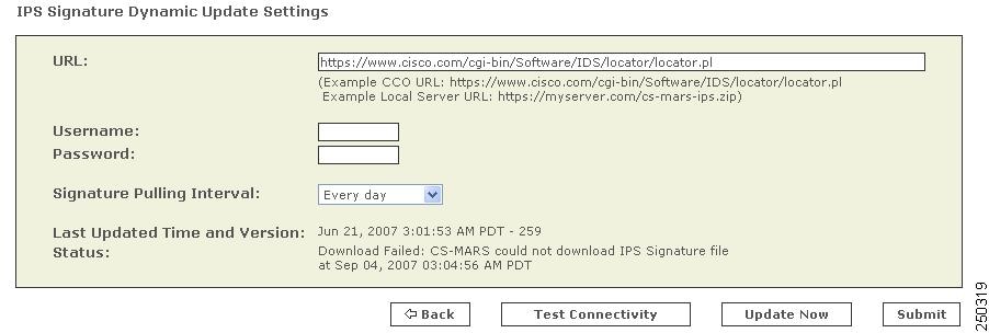
To specify the dynamic update settings, follow these steps:
Step 1
Click ADMIN > System Setup > IPS Signature Dynamic Update Settings.
Step 2
Enter the following values:
•
URL. Verify that the path to the software locator is defined. The default value is https://www.cisco.com/cgi-bin/ida/locator/locator.pl, which is located on the Cisco Software Download site. You can specify a local server using the following example
https://myserver.com/cs-mars-ips.zip(the zip files can be downloaded from http://www.cisco.com/cgi-bin/tablebuild.pl/mars-ips-sigup).•
Username. Specify the username of the account that accesses the secure server. If you are using the default URL value, this is a CCO username.
•
Password. Specify the password associated with the username value provided.
•
Signature Pulling Interval. Specify the interval at which the signature updates should be pulled from the server identified in the URL field. Valid options include: Never (default), Every 1, 2, 3, 6, or 12 hours, or Every 1 to 14 days.
Step 3
To verify the settings re correct, click Test Connectivity.
Step 4
Once the settings are verified, click Submit.
Step 5
Click Activate.
Troubleshooting IPS Signature Dynamic Updates
Two types of failures can occur, and they are identified in the Status field of the IPS Signature Dynamic Update Settings page:
•
Failure to download the package. Verify that the MARS Appliance has connectivity to the specified destination and that it is using the correct username and password.
•
Failure to install. Indicates a problem with the package itself, possibly corrupted during the download.
Custom IPS Signature Updates
Cisco IPS 6.0 enables you to define custom signatures for Cisco IPS devices. Before you can define an inspection rule in MARS that fires when that signature is detected, you must map that signature to a MARS event type.
To enable this mapping within MARS, you must perform the following tasks:
1.
Define a custom signature map file (an XML file) that maps between the custom IPS signature and a MARS event type.
2.
Import that custom map file into the Local Controller that monitors the Cisco IPS device on which that custom signature is running.

Note
Cisco recommends that any Global Controller/Local Controller relationships be established prior to applying any custom signature updates.
This chapter contains the following topics:
•
File Naming, Encoding, and Structure Guidelines for the Custom Signature Map File
•
Example Custom Signature Map Files
•
Import Custom Signature Maps into MARS
File Naming, Encoding, and Structure Guidelines for the Custom Signature Map File
Adhere to the following naming conventions for any XML file that maps a custom Cisco IPS signature to a MARS event type:
•
<number>.custom.inc.xml—Where <number> is an integer . Start with 1 and increment for each additional signature (for example, 1.custom.inc.xml) This number indicates the version number of the custom signature package. Subsequent updates must increment this version number.
MARS uses this number to ensure that the Local Controllers are synchronized with the Global Controller. The Help About page of each MARS appliance displays the customer signature version, such as Custom version: 1.
The following elements or attributes are required for the custom signature XML mapping file:
•
encoding—The header of the XML file varies based on the version of software running on the MARS appliance. If the software version is 4.3.1, then the header should be <?xml version="1.0" encoding="ISO-8859-1"?>. Otherwise, if it is running 5.3.1, the header must be <?xml version="1.0" encoding="UTF-8"?>.
•
<EventType />—This element specifies the custom signature ID for this event. The EVENT_TYPE attribute value identifies either an existing MARS event type or a new MARS event type. If it is a new MARS event type, it should be in the range of 90000000-9049000. For example: ET-9000000. The prefix "ET-xxxxxxx" is required for all values in this attribute. This value range is reserved for custom signature IDs.

Note
If the ID maps to a previously used custom ID, information for that custom event is updated with the data in this XML file. If ID maps to a system event type, the information is not updated.
•
<EVENT_PRIORITY />—This element organizes the priority of this custom signature. The expected value is one of the following: HIGH, MEDIUM, or LOW. The event priority value should match the severity of the firing signature as configured on the Cisco IPS device.
•
<EVENT_TYPE_NAME />—This element names the custom signature event. The expected value is a string of up to 300 characters. Valid character sets are WE8ISO8859P1 for 4.3.1 and AL32UTF8 for 5.3.1. Cisco recommends that this event type name match that of the signature name as configured on the Cisco IPS device.
•
<LONG_DESCRIPTION />—This element describes the custom signature event. Acceptable value is a "unlimited" string of characters. Valid character sets are WE8ISO8859P1 for 4.3.1 and AL32UTF8 for 5.3.1.
•
<Device Event Type DEVICE_ET="signatureId/subId"/>—The DEVICE_ET attribute of this element identifies the IPS custom signatureId/subId. For example, if the IPS signature has sigID=60001 and subID=0 then DEVICE_ET=NR-60001/0. The prefix "NR-" is required for all values in this attribute.
•
<DeviceType DEVICE_TYPE="Cisco IPS"/>—The DEVICE_TYPE attribute value indicates that all signatures originate from a Cisco IPS device. You must specify this value as Cisco IPS in the mapping file.
•
<EventTypeGroup>—The value of this required element must be an existing MARS event type group. You can map MARS event types to more than one event type group.
Example Custom Signature Map Files
This example, 1.custom.inc.xml, maps the custom signature NR-60000/0 to the new MARS normalized event type ET-9000001. It is written for a MARS appliance running 5.3.1:
<?xml version="1.0" encoding="UTF-8"?>
<CS_MARS_EVENT_DATA_UPDATE xsi:schemaLocation="EventDataUpdate.xsd"
xmlns="http://www.cisco.com/2007/CS-MARS/EVENT-DATA-UPDATE"
xmlns:xsi="http://www.w3.org/2001/XMLSchema-instance">
    <EventTypeList>
        <EventTypeListElement>
            <EventType EVENT_TYPE="ET-9000001">
                <EVENT_PRIORITY>LOW</EVENT_PRIORITY>
                <EVENT_TYPE_NAME>Custom Event 9000001</EVENT_TYPE_NAME>
                <LONG_DESCRIPTION>This is custom event</LONG_DESCRIPTION>
                <CVE_NAME>String</CVE_NAME>
                <AffectedPlatforms>
                    <OSInfo>
                        <Vendor>String</Vendor>
                        <Model>String</Model>
                        <Version>String</Version>
                        <Patch>String</Patch>
                    </OSInfo>
                    <ApplicationInfo>
                        <Program>String</Program>
                        <ProgramVersion>String</ProgramVersion>
                        <Application>
                            <Vendor>String</Vendor>
                            <Model>String</Model>
                            <Version>String</Version>
                            <Patch>String</Patch>
                        </Application>
                    </ApplicationInfo>
                </AffectedPlatforms>
                <VULNTY_FLAG>0</VULNTY_FLAG>
                <DENY_FLAG>0</DENY_FLAG>
                <INFO_LINKS>http://cve.mitre.org</INFO_LINKS>
                <FP_CONDITION>None</FP_CONDITION>
                <RECOM_ACTION>None</RECOM_ACTION>
            </EventType>
            <EventTypeGroup ET_GROUP_NAME="Penetrate/BufferOverflow/Web"/>
            <DeviceEventType DEVICE_ET="NR-60001/0">
                <DeviceType DEVICE_TYPE="Cisco IPS"/>
                <LINKS>http://www.mycompany.com</LINKS>
            </DeviceEventType>
        </EventTypeListElement>
    </EventTypeList>
    <Version>001</Version>
</CS_MARS_EVENT_DATA_UPDATE>
To remap this signature, NR-60000/0, to a different MARS event type, create a new xml file named 2.custom.inx.xml and change the <EventType> attribute to a different MARS event type, such as ET-3002071 ( a system MARS normalized event type).
If the MARS normalized event type is the new user-created normalized event type, you can modify the information of the event type. This example, 3.custom.inc.xml, sets the priority to HIGH and it is written for a MARS appliance running 4.3.1:
<?xml version="1.0" encoding="ISO-8859-1"?>
<CS_MARS_EVENT_DATA_UPDATE xsi:schemaLocation="EventDataUpdate.xsd"
xmlns="http://www.cisco.com/2007/CS-MARS/EVENT-DATA-UPDATE"
xmlns:xsi="http://www.w3.org/2001/XMLSchema-instance">
    <EventTypeList>
        <EventTypeListElement>
            <EventType EVENT_TYPE="ET-9000001">
                <EVENT_PRIORITY>HIGH</EVENT_PRIORITY>
                <EVENT_TYPE_NAME>Custom Event 9000001</EVENT_TYPE_NAME>
                <LONG_DESCRIPTION>This is custom event</LONG_DESCRIPTION>
                <CVE_NAME>String</CVE_NAME>
                <AffectedPlatforms>
                    <OSInfo>
                        <Vendor>String</Vendor>
                        <Model>String</Model>
                        <Version>String</Version>
                        <Patch>String</Patch>
                    </OSInfo>
                    <ApplicationInfo>
                        <Program>String</Program>
                        <ProgramVersion>String</ProgramVersion>
                        <Application>
                            <Vendor>String</Vendor>
                            <Model>String</Model>
                            <Version>String</Version>
                            <Patch>String</Patch>
                        </Application>
                    </ApplicationInfo>
                </AffectedPlatforms>
                <VULNTY_FLAG>0</VULNTY_FLAG>
                <DENY_FLAG>0</DENY_FLAG>
                <INFO_LINKS>http://cve.mitre.org</INFO_LINKS>
                <FP_CONDITION>None</FP_CONDITION>
                <RECOM_ACTION>None</RECOM_ACTION>
            </EventType>
            <EventTypeGroup ET_GROUP_NAME="Penetrate/BufferOverflow/Web"/>
            <DeviceEventType DEVICE_ET="NR-60001/0">
                <DeviceType DEVICE_TYPE="Cisco IPS"/>
                <LINKS>http://www.mycompany.com</LINKS>
            </DeviceEventType>
        </EventTypeListElement>
    </EventTypeList>
    <Version>001</Version>
</CS_MARS_EVENT_DATA_UPDATE>
Import Custom Signature Maps into MARS
Once you've defined a custom signature map, you can import that map into the Local Controller. This operation allows MARS to begin processing events about your custom signature and allow you to include such events in event type groups and inspection rules.
Before You Begin
The following requirements must be satisfied before attempting this procedure:
•
An xml file that defines the custom signature mappings and that adheres to the guidelines specified in File Naming, Encoding, and Structure Guidelines for the Custom Signature Map File.
•
A http server that hosts the xml file to be uploaded into the Local Controller.
To import a custom signature map file into MARS, follow these steps:
Step 1
To import a customer signature map file, click Admin > System Setup > IPS Custom Signature Update in the web interface of the Local Controller.

Step 2
Enter the local server and the xml filename in the URL field.
This server identifies the HTTP server from which MARS can download the custom XML file. For example,
https://www.myserver.com/1.custom.inc.xml.Step 3
If required by the local server, enter the Username/password required for the Local Controller to authenticate to that server.
Step 4
Click Update Now to start the on demand custom signature import.
Step 5
Click Activate to enable the custom signatures on the Local Controller.
Cisco IPS Modules
MARS can monitor Cisco IPS modules installed in Cisco switches and Cisco ASA appliances. To prepare these modules, you must perform the following tasks:
•
Define the base module, either the router, switch, or Cisco ASA, as defined in Cisco Router Devices, page 4-1, Cisco Switch Devices, page 4-9, and Cisco Firewall Devices (PIX, ASA, and FWSM), page 5-1.
•
Bootstrap the base module to enable SDEE traffic on the Cisco IPS module, to forward events to the MARS Appliance, and to enable MARS to access the SDEE events stored on the modules. Module access enables MARS to retrieve trigger packets and IP log information.
•
Add the IPS feature set t the base module previously defined in the web interface.
This section contains the following topics:
•
Enable SDEE on the Cisco IOS Device with an IPS Module
•
Add an IPS Module to a Cisco Switch or Cisco ASA
The following topic also supports the configuration of the Cisco IPS modules:
•
Verify that MARS Pulls Events from a Cisco IPS Device
Enable DTM Support
To support DTM, you must configure your IPS module as follows:
•
Purchase or enable the IOS IPS feature set.
•
Enable HTTPS for SDEE.
•
Enable SSH to discover settings, which is the method recommended over Telnet.
Enable SDEE on the Cisco IOS Device with an IPS Module
In addition to enabling either Telnet or SSH for configuration discovery on a Cisco IOS device, you must also enable SDEE on the device that supports IPS module. SDEE is used to publish events to MARS about signatures that have fired.
To enable SDEE protocol on the Cisco IOS device that supports IPS module, perform the following steps:
Step 1
Log in to the Cisco IOS device using the enable password.
Step 2
Enter the following commands to enable MARS to retrieve the events from the IPS module:
Router(config)#ip http secure-serverRouter(config)#ip ips notify sdeeRouter(config)#ip sdee subscriptions 3Router(config)#ip sdee events 1000Router(config)#no ip ips notify log
Note
The "no ips notify log" causes the IPS modules to stop sending IPS events over syslog.
Add an IPS Module to a Cisco Switch or Cisco ASA
You can enable in-line IPS functionality and signature detection in multi-purpose Cisco platforms. You can identify an IDS-M2 running in a Cisco Switch or an ASA-SSM running in a Cisco ASA. To represent either of these modules, you must define the settings for the module as part of the base platform, which must be previously defined under Admin > System Setup > Security and Monitor Devices.
To add an IPS module to a Cisco Switch of Cisco ASA, follow these steps:
Step 1
Click Admin > System Setup > Security and Monitor Devices.
Step 2
From the list of devices, select the Cisco switch or Cisco ASA to which you want to add the IPS module and click Edit.
Step 3
Click Add Module.

Step 4
Select Cisco IPS 5.x or Cisco IPS 6.x in the Device Type list.
For Cisco switches, you can also add a Cisco IPS 4.0 module or an IDS 3.1 module. You configure these modules just as you would a standalone sensor. For instructions on configuring these modules, refer to Cisco IDS 3.1 Sensors and Cisco IDS 4.0, IPS 5.x, and IPS 6.x Sensors.
Figure 7-1 Configure Cisco IPS 5.x or 6.x

Step 5
Enter the hostname of the sensor in the Device Name field.
Step 6
Enter the administrative IP address in the Reporting IP field.
Step 7
The Reporting IP address is the same address as the administrative IP address.
Step 8
In the Login field, enter the username associated with the administrative account that will be used to access the reporting device.
Step 9
In the Password field, enter the password associated with the username specified in the Login field.
Step 10
In the Port field, enter the TCP port on which the webserver running on the sensor listens.
The default HTTPS port is 443.

Note
While it is possible to configure HTTP only, MARS requires HTTPS.
Step 11
For attack path calculation and mitigation, specify the networks being monitored by the sensor. Do one of the following:
To manually define the networks, select the Define a Network radio button.
a.
Enter the network address in the Network IP field.
b.
Enter the corresponding network mask value in the Mask field.
c.
Click Add to move the specified network into the Monitored Networks field.
d.
Repeat as needed.
To select the networks that are attached to the device, click the Select a Network radio button.
a.
Select a network from in the Select a Network list.
b.
Click Add to move the selected network into the Monitored Networks field.
c.
Repeat as needed.
Step 12
Click Test Connectivity to verify the configuration.
Step 13
To save your changes, click Submit.
Step 14
To enable MARS to start sessionizing events from this module, click Activate.
IBM Proventia Management/ISS SiteProtector to Define Global Event Policies
To define SiteProtector as a reporting device, see IBM Proventia Management/ISS SiteProtector 2.0 as A Reporting Device.

Note
This topic describes how to use Site Protector to configure the ISS NIDS and HIDS; Site Protector is not a device type that can be monitored or used as an aggregation point for ISS event data from the perspective of MARS. Prior to 4.3.1 and 5.3.1, MARS could not parse event data from Site Protector, unless you developed a custom event parser for each event type.
MARS supports ISS NIDS and HIDS event retrieval via SNMP. However, when configuring ISS RealSecure sensors (NIDS) and hosts (HIDS), you must configure each active signature to send an alert to the MARS Appliance. This task can be very tedious as it must be done for each sensor and after each signature upgrade, as it resets the redirect configuration. One approach to simplifying this task is to use the SiteProtector management console to define these changes globally and apply them to each sensor.
SiteProtector 2.0 allows you to centrally manage SNMP alert destinations, such as the MARS Appliance, for group policies. You can then push these group policies to all desired host and network sensors. For each ISS signature update, you must specify the MARS Appliance as an SNMP alert destination before you apply the downloaded signatures to sensors using Site Protector.

Note
By default, the group policy response configuration is supported only on Proventia G400 and G2000 models. For all other models, including the G100 mentioned, a firmware upgrade is required. See the documentation that came with SiteProtector for more information.
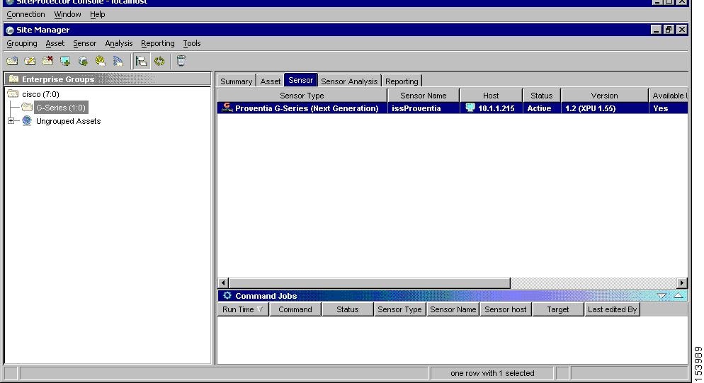
To perform the major configuration steps required to use Site Protector to forward the SNMP alerts generated by sensors to MARS Appliance, follow these steps:
Step 1
Using the Add Sensor Wizard, register the sensor to Site Protector Console.
Other methods exist for registering sensors in Site Protector. For more information on using the Wizard as well as these other methods, see Chapter 9, Registering Software Managed by SiteProtector, on page 105 at the following URL:
http://documents.iss.net/literature/SiteProtector/SPUserGuideforSecurityManagers20SP52.pdf
Step 2
Right-click the sensor to edit, and click Edit Settings on the shortcut menu.
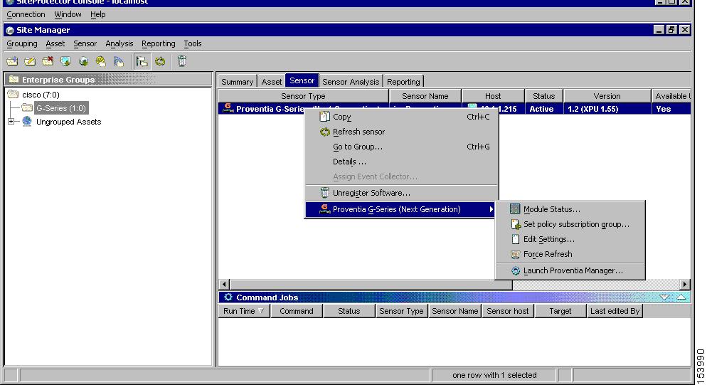
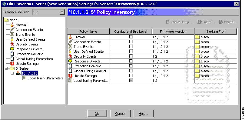
The Edit Settings dialog appears.
Step 3
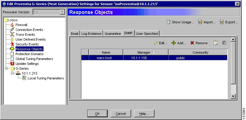
Create a new SNMP response that sends messages to the IP address of the MARS Appliance:
a.
Select Response Objects from the settings tree.
b.
Select the SNMP tab.
c.
Click Add to create a new SNMP response object using the IP address of the MARS Appliance.
Step 4
Select the Security Events to configure new SNMP destination.
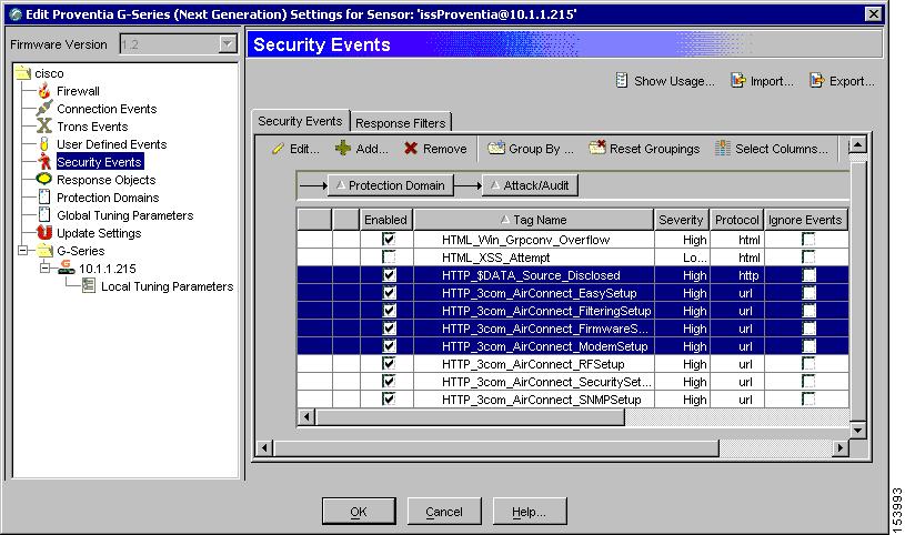
a.
Select Security Events under the sensor folder.
b.
Select the required security events from the Security Events tab.
The Group By button allows you to group policies using any number of parameters.

Note
You can also select policies and edit them at the group level.
c.
Click Edit to configure SNMP response of all the selected policies.
Step 5
Select the MARS Appliance on SNMP tab.
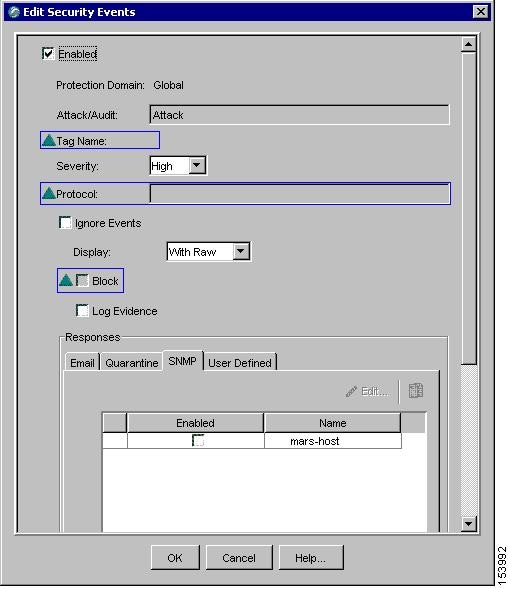
a.
Enable all the security events by selecting the Enabled checkbox located at the top of the Edit Security Events dialog box.
a.
Select the SNMP tab under Responses, and then select the Enabled checkbox next to the name of MARS Appliance created in Step 3.
a.
Click OK.
The security events and updated response target are applied to the selected sensor during the next synchronization.
IBM Proventia Management/ISS SiteProtector 2.0 as A Reporting Device
MARS supports ISS NIDS and HIDS event retrieval via SNMP. However, when configuring ISS RealSecure sensors (NIDS) and hosts (HIDS), you must configure each active signature to send an alert to the MARS Appliance. This task can be very tedious as it must be done for each sensor and after each signature upgrade, as it resets the redirect configuration. Two approaches that simplify this task exist:
•
Use the SiteProtector management console to define these changes globally and apply them to each sensor. In this case, MARS parses SNMP event data from the managed ISS NIDS and HIDS devices.
SiteProtector 2.0 allows you to centrally manage SNMP alert destinations, such as the MARS Appliance, for group policies. You can then push these group policies to all desired host and network sensors. For each ISS signature update, you must specify the MARS Appliance as an SNMP alert destination before you apply the downloaded signatures to sensors using Site Protector.
By default, the group policy response configuration is supported only on Proventia G400 and G2000 models. For all other models, including the G100 mentioned, a firmware upgrade is required. See the documentation that came with SiteProtector for more information.
•
Define Site Protector as a reporting device. It acts as an aggregation point for ISS NIDS and HIDS event data . In this case, MARS parses SNMP event data from Site Protector.
This topic describes how to configure and define Site Protector as a reporting device. To enable SiteProtector as a reporting device in MARS, define the SiteProtector console as the reporting device. The SiteProtector receives alerts from the ISS agents that it monitors, and it forwards those alerts to MARS as SNMP notifications.
When MARS receives the SNMP notification, the source IP address in the notification is that of the ISS agent that originally triggered the event, rather than the SiteProtector that forwarded it. Therefore, MARS requires host definitions for each of the ISS agents that can potentially trigger an event. These definitions are added as sub-components under the device definition of the SiteProtector console.
MARS discovers ISS agents as they generate alerts, eliminating the need to manually define them. MARS parses the alert to identify the ISS agent hostname and to discover the host operating system (OS). MARS uses this information to add any undefined agents as children of the SiteProtector as a host with either the Generic Windows (all Windows) or Generic (Unix or Linux) operating system value. You are still required to define the SiteProtector; however, you are not required to define each agent. The default topology presentation for discovered ISS agents is within a cloud.
The first SNMP notification from an unknown ISS agent appears to originate from the SiteProtector. MARS parses this notification and defines a child agent of the SiteProtector using the discovered settings. Once the agent is defined, all subsequent messages appear to originate from the ISS agent.
This section contains the following topics:
•
Configure SiteProtector to Forward SNMP Notifications to MARS
•
Add and Configure a SiteProtector Device in MARS
Configure SiteProtector to Forward SNMP Notifications to MARS
The only required configuration is to ensure that SiteProtector forwards the SNMP notifications that it receives from agents to MARS. From these notifications, MARS is able to discover the agent and its relevant settings. It is also from these events that MARS learns about the host-level activities transpiring on your network.
To forward all notifications to the MARS Appliance, follow these steps:
Step 1
Log in to the Site Protector console.
Step 2
Click Grouping > Site Management > Central Responses > Edit settings.
The Edit Central response Settings Window appears.
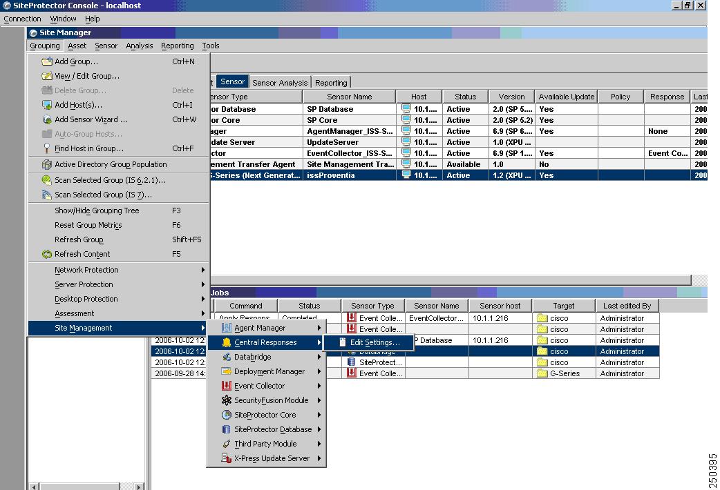
Step 3
Click Response Objects > SNMP > Add to add a new response object that represents the MARS Appliance to which events should be forwarded.
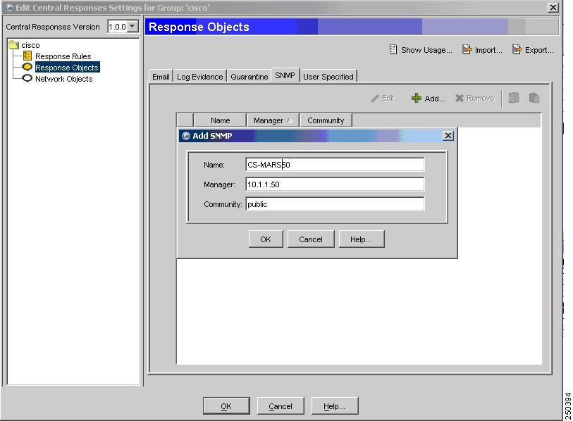
Step 4
Enter values for the following fields that correspond to the MARS Appliance:
•
Name (hostname)
•
Manager (IP address)
•
Community (public)
Step 5
Click OK.
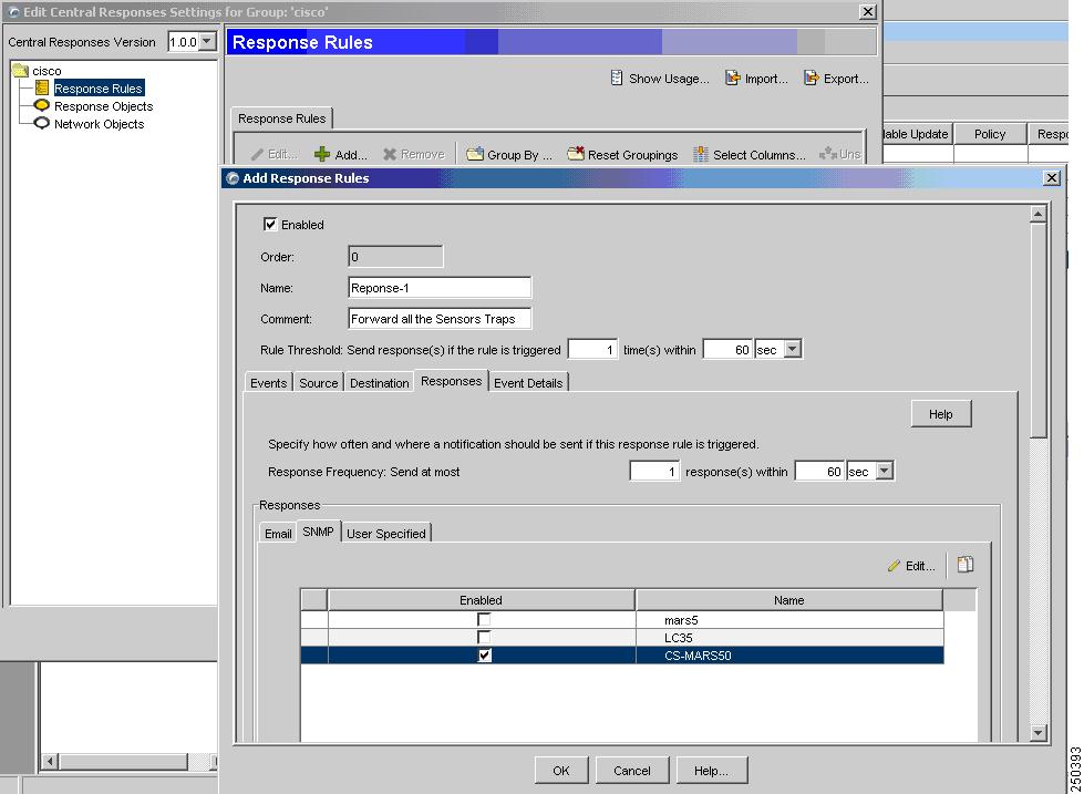
The MARS Appliance appears as a response object. You can now define response rules forward SNMP traps to this object. The default SNMP port is 612. One ore more response object is associated with each response rule. Therefore, the response object is not used until it is associated with an enabled response rule.
Step 6
To add a response rule, click Response Rules > Add.
Step 7
Specify the following value:
•
Enable—When selected, it enables the response rule.
•
Name—Identifies the name of the response rule.
•
Comments— Provides a description of the response rule.
Step 8
Click the SNMP tab, and under the Enabled column, select the checkbox next to the response object defined inStep 4.

Note
Multiple response objects can be enabled for each response rule.
Step 9
Click on OK to save the rule, enable it, and enable the response object that represents the MARS Appliance.
Step 10
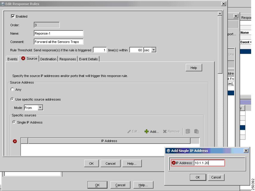
(Optional) By default, a rule matches on any source or destination IP addresses. To refine the rule to match on a specific source IP address, modify the rule, and then select the Source tab.
Specify the following values:
•
Use specific source addresses—Select this option to restrict the rule based on IP address of the source.
•
Mode—Specify that the rule should either be From or Not From the IP address.
•
Click Add—Define one or more IP addresses to clarify the rule's scope.
Similarly, you can modify the rule depending on the destination IP addresses.
Step 11
Close the program.
Add and Configure a SiteProtector Device in MARS
Before you can identify the agents, you must add the SiteProtector to MARS. All ISS agents forward notifications to the SiteProtector, and the SiteProtector forwards SNMP notifications to MARS. Once you define the SiteProtector and activate the device. MARS can discover the agents that are managed by that SiteProtector. However, you can also chose to manually add the agents.
To add a SiteProtector to MARS, follow these steps:
Step 1
Click Admin > Security and Monitor Devices > Add.
Step 2
From the Device Type list, select Add SW security apps on a new host or Add SW security apps on existing host.
Step 3
Enter the Device Name and IP addresses if adding a new host.
Step 4
Click Apply.
Step 5
Click Reporting Applications tab.
Step 6
From the Select Application list, select ISS SiteProtector 2.x.
Step 7
Click Add.
Step 8
The Management Console page appears.
Step 9
Do one of the following:
•
To save your changes and allow the ISS agents to be discovered automatically, click Submit, and then click Done.

Note
Discovered agents are named Generic Real Secure agent, as no version information is contained in the SNMP events.
•
To add a single ISS RealSecure NIDS or ISS RealSecure HIDS agent manually, continue with Add an ISS Agent Manually.
Add an ISS Agent Manually
MARS automatically discovers ISS agents when it receives an event from the agent. Discovered agents are named Generic Real Secure agent, as no version information is contained in the SNMP events. However, you can manually add a ISS Agent (ISS RealSecure NIDS or ISS RealSecure HIDS devices) as a child of the SiteProtector device. This feature allows you to represent all of your agents, even if they have not generated any notifications. In turn, this definition allows you to identify devices that are not reporting results.
To add ISS Agents manually, follow these steps:
Step 1
Click Admin > Security and Monitoring Devices.
Step 2
From the list of devices, select the host running SiteProtector, and click Edit.
Step 3
Click the Reporting Applications tab, select ISS SiteProtector in the Device Type list, and click Edit.
Step 4
Click the Add Agent.
Step 5
Do one of the following:
•
Select the existing device, click Edit Existing, and continue with Step 8.
A page displays with the values pre-populated for hostname, reporting IP address, and at least one interface.
•
Click Add New, and continue with Step 6.
Step 6
In the Device Name field, enter the hostname on which this ISS Agent resides.
This value should reflect the DNS entry for this device.
Step 7
In the Reporting IP field, enter the IP address that the agent uses to send logs to the SiteProtector.
Step 8
Define each interface that is configured for this host by specifying the interface name, IP address, and network mask. To add a new interface, click Add Interface.
The interface settings are used for attack path calculation. It is very important that you identify any dual-homed hosts by defining each interface.
Step 9
In the Device Application field, select one of the following values:
•
ISS RealSecure 6.5
•
ISS RealSecure 7.0
Step 10
Select either the NIDS or HIDS option.
If you select HIDS, the Monitored Networks field disappears.
Step 11
If you selected NIDs, continue with Step 12. Otherwise, continue with Step 14.
Step 12
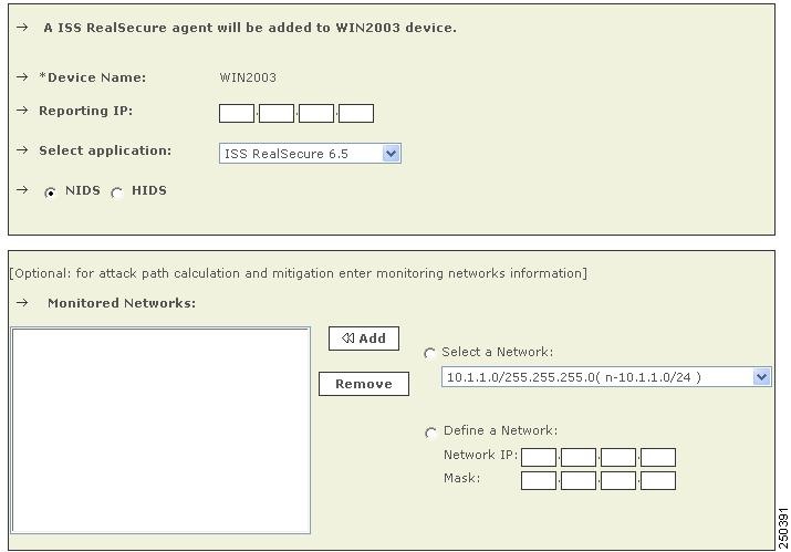
For attack path calculation and mitigation, specify the networks being monitored by the sensor. Do one of the following:
To manually define the networks, select the Define a Network radio button.
a.
Enter the network address in the Network IP field.
b.
Enter the corresponding network mask value in the Mask field.
c.
Click Add to move the specified network into the Monitored Networks field.
d.
Repeat as needed.
To select the networks that are attached to the device, click the Select a Network radio button.
a.
Select a network from in the Select a Network list.
b.
Click Add to move the selected network into the Monitored Networks field.
c.
Repeat as needed.
Step 13
Continue with Step 16.
Step 14
For multiple interfaces, click on Add Inerfaces, and specify the new interfaces' name, IP address, and network mask.
Figure 7-2 Adding Multiple Interfaces

Step 15
Click Apply.
Step 16
Click Submit, and then click Done.
Step 17
To activate this device, click Activate.
ISS RealSecure 6.5 and 7.0
To configure ISS RealSecure, you must perform the following four tasks:
1.
Prepare each ISS sensor as follows:
•
Edit the
common.policyfiles to point to the MARS Appliance as an SNMP target.•
Modify the
current.policyfiles to configure each signature so that the SNMP notification is a default response when triggered.•
Edit the
response.policyfiles to specify the IP of the SNMP manager (MARS Appliance) and the community string.•
Restart the ISS daemon for the changes to take effect.
For more information, see Configure ISS RealSecure to Send SNMP Traps to MARS.
2.
Add the ISS sensor to MARS as a network-based IDS device. For more information, see Add an ISS RealSecure Device as a NIDS.
3.
Click Activate to enable proper processing of received events.
Configure ISS RealSecure to Send SNMP Traps to MARS
To configure an ISS RealSecure sensor, follow these steps:
Step 1
Log into the sensor.
Step 2
Locate the
common.policyfiles in these directories:Microsoft WindowsProgram Files\ISS\issSensors\server_sensor_1Program Files\ISS\issSensors\network_sensor_1Linux/opt/ISS/issSensors/server_sensor_1/opt/ISS/issSensors/network_sensor_1Step 3
Open the
common.policyfiles in a text editor.Step 4
Change the line that reads:
Manager =Sto:
Manager =S <MARS's IP address>If MARS Appliance's IP address is NATed, you may need to use the NATed address. If you use the MARS Appliance's IP address as the destination IP address, make sure the SNMP trap can reach MARS Appliance.
Step 5
Save these edited files and exit the editor.
Step 6
Locate the
current.policyfiles in these directories:Microsoft WindowsProgram Files\ISS\issSensors\server_sensor_1Program Files\ISS\issSensors\network_sensor_1Linux/opt/ISS/issSensors/server_sensor_1/opt/ISS/issSensors/network_sensor_1Step 7
Open the
current.policyfiles in a text editor.Edit each signature to have SNMP as one of its responses, and set the choice for SNMP trap as default. For example, in this original signature:
[\template\features\AOLIM_File_Xfer\Response\];[\template\features\AOLIM_File_Xfer\Response\DISPLAY\];Choice =S Default;[\template\features\AOLIM_File_Xfer\Response\LOGDB\];Choice =S LogWithoutRaw;Insert the following bolded lines to make it look similar to the following:
[\template\features\AOLIM_File_Xfer\Response\];[\template\features\AOLIM_File_Xfer\Response\DISPLAY\];Choice =S Default;[\template\features\AOLIM_File_Xfer\Response\SNMP\];Choice =S Default;[\template\features\AOLIM_File_Xfer\Response\LOGDB\];Choice =S LogWithoutRaw;Step 8
Save these edited files and exit the editor.
Step 9
Locate the
response.policyfiles in these directories:Microsoft WindowsProgram Files\ISS\RealSecure SiteProtector\ConsoleLinux/opt/ISS/RealSecure SiteProtector/ConsoleStep 10
Edit the
response.policyfiles to specify the IP of the SNMP manager (MARS Appliance) and the community string:SMTP_HOST =S ;addr_1 =S ;[\Response\SNMP\];[\Response\SNMP\Default\];Manager =S ;Community =S public;to:
Manager =S <MARS's IP address> ;Community = S <string> public;If MARS Appliance's IP address is NATed, you may need to use the NATed address. If you use the MARS Appliance's IP address as the destination IP address, make sure the SNMP trap can reach MARS Appliance.
Step 11
Save these edited files and exit the editor.
Step 12
Restart the ISS daemon.
•
For sensors installed on Microsoft Windows, restart it in the Services menu.
•
For sensors installed on Linux, run:
/etc/init.d/RealSecure stop/etc/init.d/RealSecure start
Add an ISS RealSecure Device as a NIDS
Step 1
Click Admin > System Setup > Security and Monitor Devices > Add.
Step 2
From the Device Type list, select Add SW Security apps on a new host or Add SW security apps on existing host.
Step 3
Enter the Device Name.
Step 4
Click Apply.
Step 5
Click on Reporting Applications tab.
Step 6
From the Select Application list, select ISS RealSecure 6.5 or ISS RealSecure 7.0.
Step 7
Click Add.
Step 8
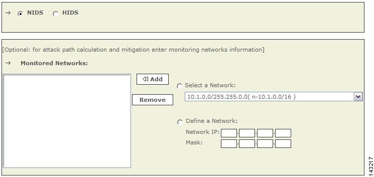
Click the NIDS radio button, if it is not already selected.
Figure 7-3 Configure ISS Real Secure NIDS
Step 9
For attack path calculation and mitigation, specify the networks being monitored by the sensor. Do one of the following:
To manually define the networks, select the Define a Network radio button.
a.
Enter the network address in the Network IP field.
b.
Enter the corresponding network mask value in the Mask field.
c.
Click Add to move the specified network into the Monitored Networks field.
d.
Repeat as needed.
To select the networks that are attached to the device, click the Select a Network radio button.
a.
Select a network from in the Select a Network list.
b.
Click Add to move the selected network into the Monitored Networks field.
c.
Repeat as needed.
Step 10
To save your changes, click Submit.
Step 11
To enable MARS to start sessionizing events from this module, click Activate.
Add an ISS RealSecure Device as a HIDS
Step 1
Click Admin > System Setup > Security and Monitor Devices > Add.
Step 2
From the Device Type list, select Add SW Security apps on a new host or Add SW security apps on existing host.
Step 3
Enter the Device Name.
Step 4
Click Apply.
Step 5
Click on Reporting Applications tab.
Step 6
From the Select Application list, select ISS RealSecure 6.5 or ISS RealSecure 7.0.
Step 7
Click Add.
Step 8
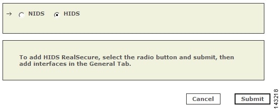
Click the HIDS radio button.
Figure 7-4 Configure ISS Real Secure HIDS
Step 9
Click Submit.
Step 10
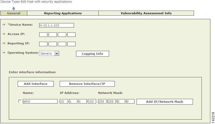
For multiple interfaces, click on General Tab, and add the new interfaces' name, IP address, and network mask.
Figure 7-5 Adding Multiple Interfaces
Step 11
Click Apply.
IntruVert IntruShield
To configure IntruVert IntruShield in MARS, you must perform the following tasks:
1.
Generate CSV file that identifies each of the IntruShield senor hosts by logging into the database to which IntruShield Manager writes and performing and saving a database query.
2.
Configure the IntruShield Manager to send SNMP traps to the MARS Appliance
3.
Define a host that represents the management console (IntruVert Manger) in MARS web interface.
4.
From that host in the MARS web interface, import the IntruShield sensor seed file to identify the IntruVert sensors running on other hosts.
The following sections provide details on performing each of these tasks:
•
Extracting Intruvert Sensor Information from the IntruShield Manager
•
Configure IntruShield Version 1.5 to Send SNMP traps to MARS
•
Configure IntruShield Version 1.8 to Send SNMP Traps to MARS
•
Add and Configure an IntruShield Manager and its Sensors in MARS
Extracting Intruvert Sensor Information from the IntruShield Manager
IntruVert sensor information is saved in a database on the IntruShield Manager host. When you configure the MARS to add Intruvert sensors, you can manually add the mapping of each Intruvert sensor name or you can extract them as a seed file from the database on the Intruvert Manager.

Note
The instructions apply for Intruvert IntruShield version 1.5. IntruVert supports both MySQL and Oracle.
To create a CSV file for IntruVert IntruShield 1.5, follow these steps:
Step 1
Log in to the database.
Step 2
Perform the query:
use lf; select name, ip_address from iv_sensor where ip_address is not NULL;
Step 3
Store the query result into a file, remove the header, trailer, and separator lines, and edit the result to a CSV format.
For example, the query result could be:+------------+------------+| name | ip_address |+------------+------------+| intruvert | 0A010134 || intruvert1 | 0A010135 |+------------+------------+2 row in set (0.00 sec)You would then edit the above file to appear as:intruvert,0A010134intruvert1,0A010135Step 4
Save the edited CSV file, move the file to an FTP server from which you can load the seed file using the MARS web interface.
Configure IntruShield Version 1.5 to Send SNMP traps to MARS
Step 1
Log in to the IntruShield Manager version 1.5.
Step 2
Click Configure.
Step 3
In the Resource Tree, click My Company.
Step 4
Click the Forwarding tab.
Step 5
In the Add SNMP Server field, enter:
a.
Target Server IP Address: Enter MARS's IP address as it appears to IntruShield.
b.
Target Server Port Number: Enter MARS's port number 162.
c.
SNMP Version: 1
d.
Check the Forward Alerts box.
e.
Select the For this and child admin domains radio button.
f.
Select the severity from the list. Cisco recommends selecting High and Medium severity.
g.
Check the Forward Faults box.
h.
Select the severity from the list. Cisco recommends selecting Error and above severity.
Step 6
Click Save and exit the program.
Configure IntruShield Version 1.8 to Send SNMP Traps to MARS
Step 1
Log in to the IntruShield Manager version 1.8.
Step 2
Click Configure.
Step 3
In the Resource Tree, click My Company.
Step 4
Click the Alert Notification tab.
Step 5
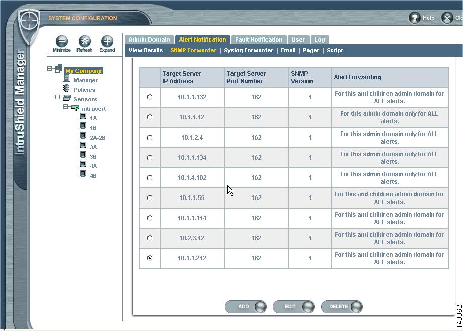
Click the SNMP Forwarder sub-tab.
Figure 7-6 IntruShield SNMP Forwarder Configuration
Step 6
Click the Add button.
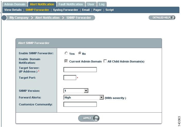
Figure 7-7 IntruShield Target SNMP Server
Step 7
On the SNMP Forwarder page, enter:
a.
Enable SNMP Forwarder: Select the Yes radio button.
b.
Target Server (IP Address): Enter MARS's IP address as it appears to IntruShield.
c.
Target Server Port Number: Enter MARS's port number 162.
d.
SNMP Version: 1
e.
Forward Alerts
f.
Select the severity from the list. Cisco recommends selecting Informational and above severity.
g.
Customize Community: Enter the community string that you want to use.
Step 8
Click Apply and exit the program.
Add and Configure an IntruShield Manager and its Sensors in MARS
Adding an IntruVert device has two distinct steps. First, you add configuration information for the for the IntruShield Manager host. Second, you add the sensors managed by that host.
•
Add the IntruShield Manager Host to MARS
•
Add IntruShield Sensors Manually
•
Add IntruShield Sensors Using a Seed File
Add the IntruShield Manager Host to MARS
To define the host and represent the management console for IntruShield, follow these steps:
Step 1
Click Admin > System Setup > Security and Monitor Devices > Add.
Step 2
From the Device Type list, select Add SW Security apps on a new host or Add SW security apps on existing host.
Step 3
Enter the Device Name and IP addresses if adding a new host.
Step 4
Click Apply.
Step 5
Click Reporting Applications tab.
Step 6
Select IntruVert IntruShield 1.5 from the Select Application list.
Step 7
To complete the definition of this console, click Add.
Figure 7-8 Add IntruShield Sensors

Step 8
Continue defining the sensors that the console manages using one of two methods:
•
Add IntruShield Sensors Manually
•
Add IntruShield Sensors Using a Seed File
Add IntruShield Sensors Manually
To add sensors manually, follow these steps:
Step 1
Click Add Sensor.
Step 2
Enter the Device Name, Sensor Name, and its Reporting IP address.
•
Device Name - the DNS entry for this device
•
Sensor Name - the name as it appears in the console
•
Reporting IP - the IP address that the agent uses to send logs to the console
Step 3
Add the interface information.
Step 4
For attack path calculation and mitigation, specify the networks being monitored by the sensor. Do one of the following:
To manually define the networks, select the Define a Network radio button.
a.
Enter the network address in the Network IP field.
b.
Enter the corresponding network mask value in the Mask field.
c.
Click Add to move the specified network into the Monitored Networks field.
d.
Repeat as needed.
To select the networks that are attached to the device, click the Select a Network radio button.
a.
Select a network from in the Select a Network list.
b.
Click Add to move the selected network into the Monitored Networks field.
c.
Repeat as needed.
Step 5
To save your changes, click Submit.
Step 6
To enable MARS to start sessionizing events from this module, click Activate.
Add IntruShield Sensors Using a Seed File
To add sensors using a seed file, follow these steps:
Step 1
Click Load From CSV.
Step 2
Enter the FTP server information and location of the CSV (comma separated values) file.
•
If you need to generate the IntruShield sensors CSV file, Extracting Intruvert Sensor Information from the IntruShield Manager.
Step 3
Click Submit.
The list of sensors appears on the management console page.
Step 4
For each sensor that appears in the management console page, select the check box next to the sensor and click Edit Sensor.
Step 5
For attack path calculation and mitigation, specify the networks being monitored by the sensor. Do one of the following:
To manually define the networks, select the Define a Network radio button.
a.
Enter the network address in the Network IP field.
b.
Enter the corresponding network mask value in the Mask field.
c.
Click Add to move the specified network into the Monitored Networks field.
d.
Repeat as needed.
To select the networks that are attached to the device, click the Select a Network radio button.
a.
Select a network from in the Select a Network list.
b.
Click Add to move the selected network into the Monitored Networks field.
c.
Repeat as needed.
Step 6
To save your changes, click Submit.
Step 7
To save the changes made to this management console and the sensors it manages, click Submit.
Step 8
To enable MARS to start sessionizing events from this module, click Activate.
Snort 2.0
MARS Expectations of the Snort Syslog Format
The following example Snort syslog messages are used to illustrate the values that are parsed by the MARS Appliance:
<161>snort: [1:2050:1] MS-SQL version overflow attempt [Classification: Misc activity]
[Priority: 3]: {UDP} 69.70.113.64:1449 -> 66.243.153.44:1434
<119>Jul 16 10:54:39 SourceFire SFIMS: [1:469:1] ICMP PING NMAP [Classification: Attempted Information Leak] [Priority: 2] {ICMP} 210.22.215.77 -> 67.126.151.137<161>Mar 12 18:02:22 snort: [ID 702911 local4.alert] [119:2:1] (http_inspect) DOUBLE DECODING ATTACK {TCP} 10.1.1.21:60312 -> 10.1.1.69:80The MARS parser expects the pattern: "[<generator id>:<snort id>:<revision number>]" to identify the event as one originating from a Snort device. One that determination is made, MARS looks for either "{<protocol_string>} <ip>:<port> -> <ip>:<port>" or "{<protocol_string>} <ip> -> <ip>" to identify the five-tuple values.
Configure Snort to Send Syslogs to MARS
For Snort, use the syslog as your output plugin. Configure your syslogd to send copies to another host. On most older-style systems (Solaris/Linux), you need to edit /etc/syslog.conf. (Assuming that the system is based on syslogd, and not any of the newer system logging facilities. The newer logging facilities are not supported by Snort.)
To configure Snort to send syslog messages to the MARS Appliance, follow these steps:
Step 1
Make Snort's output go to syslog with log facility local4 in snort.conf (you can pick any local facility that's unused.)
output alert_syslog: LOG_LOCAL4 LOG_ALERTsnort.conf is normally in /etc/snort.
Step 2
Add a redirector in your /etc/syslog.conf on your Snort box to send syslog to MARS.
local4.alert @IPAddrOffMarsboxStep 3
Restart the Snort daemon and the syslogd daemon on your Snort box.
Add the Snort Device to MARS
To add the Snort device to MARS, follow these steps:
Step 1
Click Admin > System Setup > Security and Monitor Devices > Add
Step 2
From the Device Type list, select Add SW Security apps on a new host or Add SW security apps on existing host
Step 3
Enter the Device Name and IP addresses if adding a new host.
Step 4
Click Apply
Step 5
Click Reporting Applications tab
Step 6
From the Select Application list, select Snort Snort 2.0
Step 7
Click Add
Step 8
For attack path calculation and mitigation, specify the networks being monitored by the sensor. Do one of the following:
To manually define the networks, select the Define a Network radio button.
a.
Enter the network address in the Network IP field.
b.
Enter the corresponding network mask value in the Mask field.
c.
Click Add to move the specified network into the Monitored Networks field.
d.
Repeat as needed.
To select the networks that are attached to the device, click the Select a Network radio button.
a.
Select a network from in the Select a Network list.
b.
Click Add to move the selected network into the Monitored Networks field.
c.
Repeat as needed.
Step 9
To save your changes, click Submit.
Step 10
To enable MARS to start sessionizing events from this module, click Activate.
Symantec ManHunt
Symantec ManHunt Side Configuration
Step 1
Login to the Symantec ManHunt with appropriate username and password.
Step 2
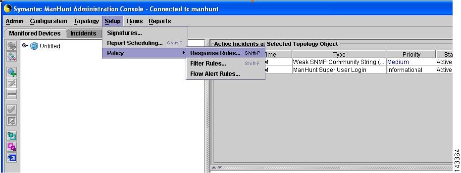
In the main screen, click Setup > Policy > Response Rules, then Response Rules window will appear.
Figure 7-9 ManHunt Configuration
Step 3
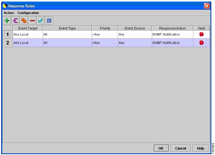
In the Response Rules window, click Action > Add response Rules.
Step 4
Click in the field of Response Action
Figure 7-10 ManHunt Response Rule Config
Step 5
In the left menu, click SNMP Notification and enter the following information:
a.
SNMP Manager IP address: Reporting IP address of MARS
b.
Maximum number of SNMP notification: (Example: 100000).
c.
Delay between SNMP notification (mins): (Example: 1 min)
Step 6
Click OK to return to main screen.
MARS Side Configuration
Add Configuration Information for Symantec ManHunt 3.x
Step 1
Click Admin > System Setup > Security and Monitor Devices > Add
Step 2
From the Device Type list, select Add SW Security apps on a new host or Add SW security apps on existing host
Step 3
Enter the Device Name and IP addresses if adding a new host.
Step 4
Click Apply
Step 5
Click Reporting Applications tab
Step 6
From the Select Application list, select Symantec ManHunt 3.x
Step 7
Click Add
Step 8
For attack path calculation and mitigation, specify the networks being monitored by the sensor. Do one of the following:
To manually define the networks, select the Define a Network radio button.
a.
Enter the network address in the Network IP field.
b.
Enter the corresponding network mask value in the Mask field.
c.
Click Add to move the specified network into the Monitored Networks field.
d.
Repeat as needed.
To select the networks that are attached to the device, click the Select a Network radio button.
a.
Select a network from in the Select a Network list.
b.
Click Add to move the selected network into the Monitored Networks field.
c.
Repeat as needed.
Step 9
To save your changes, click Submit.
Step 10
To enable MARS to start sessionizing events from this module, click Activate.
NetScreen IDP Device and Server Support
MARS supports multiple versions of NetScreen IDP. How this support is realized within MARS differs based on the version of the sensor that you are running.
•
NetScreen IDP-Management Server—The NetScreen IDP Management Server is the management software for IDP version 2.x and 3.x sensors. Usually, the IDP-Management Server is installed on the IDP appliance. However, it can be removed from the IDP appliance an and installed on a Solaris or Linux server. In MARS, IDP v2.1 and 3.x are both supported as agents on a Linux host running IDP-Management Server.
•
NetScreen Security Manager— (NSM) provide support for the following NetScreen sensors:
–
NetScreen IDP 4.0
–
NetScreen IDP 4.1

Note
It also supports other Juniper Networks devices such as NetScreen-x, ISG-x and SSG-x. These devices are not currently supported in MARS.
IDP sensors running 4.0 and later are supported by NSM running on a Linux host. NSM forwards syslog events to MARS for processing.

Tip
Because MARS does not support multiple reporting devices on the same host (as defined by reporting IP address), IDP-Management Server and NSM cannot co-exist on the same host unless they report to MARS via different IP addresses. However, you can define multiple sensors per management server.
Adding a NetScreen IDP sensor to MARS involves two parts:
1.
Bootstrap the management server (or IDP sensor 4.1) that will publish syslog events to MARS.
2.
Add and configure the management server (or IDP 4.1 sensor) in the MARS web interface.
This section contains the following topics:
•
Bootstrap a NetScreen Security Manager
•
Bootstrap a NetScreen IDP Management Server
•
Add NetScreen Server or Sensor to MARS
Bootstrap a NetScreen Security Manager
MARS can retrieves logs from a NetScreen Security Manager server in support of IDP 4.x sensors. To prepare the NetScreen Security Manager server, you must enabling logging and syslog generation for the security policies that are running on IDP sensors that it manages.
Bootstrap a NetScreen IDP Management Server
MARS can retrieves logs from a NetScreen IDP Management Server in support of IDP 2.x and 3.x sensors. To prepare the NetScreen IDP Management Server, you must enabling logging and syslog generation for the security policies that are running on IDP sensors that it manages.
To enable logging and syslog generation, follow these steps:
Step 1
Click NetScreen-Global Pro > IDP Manager > IDP.
Step 2
Log in to the IDP Manager.
Step 3
From the main menu, click Tools > Preferences.
Step 4
In the tree on the left, click Management Server, enter the Local Controller's address in the Syslog host field, and click OK.
Step 5
Click Security Policies, and the name of your policy.
Step 6
In the Notification column, right-click anywhere in the cell in the field and select Configure.
Step 7
Check enable logging and syslog for each policy, and click OK. Repeat for all of your policies.
Step 8
From the main menu, click Policy > Install.
Add NetScreen Server or Sensor to MARS
Whether the syslog messages are being sent to MARS from a management server on behalf of sensors or an IDP 4.1 sensor is publishing the syslog messages directly to MARS, you must perform three steps:
1.
Define a Linux host that represents the management server
2.
Add configuration information about the software on the management server. This information appears as a software-based security application (a management console) running on the Linux host.
3.
Add configuration information for the IDP sensors that are managed by the server. These sensors appears as modules of a management console.
To define the IDP sensors, follow these steps:
Step 1
Click Admin > System Setup > Security and Monitor Devices > Add.
Step 2
From the Device Type list, select Add SW Security apps on a new host or Add SW security apps on existing host.
Step 3
If adding a new host, specify the following values:
enter the and IP Addresses, and click Apply.
•
Device Name—Specify a name for the host that is representing either a management server.
•
Reporting IP Address—Enter the IP address from which MARS will receive the syslog messages from this device.
•
Operating System—Select Linux.
•
IP Address and Network Mask—Under Enter interface information, specify the values of at least one interface. You must define the name, IP address, and network mask for that interface.
Step 4
Click Apply, then click Reporting Applications tab, and select one of the following values from the Select application list:
•
NetScreen IDP 2.1—Select this value to add a NetScreen IDP Management Server (IDP 2.1) to this host.
•
NetScreen IDP 3.x—Select this value to add a NetScreen IDP Management Server (IDP 3.x) to this host.
•
Juniper IDP 4.x—Select this value to add a NetScreen-Security Manager (IDP 4.x) to this host. This value is also the one that you add to specify a standalone IDP 4.1 sensor (the software version simply instructs MARS as to how to parse the incoming syslog messages).
Step 5
Click Add.
The Management Console page appears.

Step 6
To add a sensor, click Add Sensor.
The Select the device on which sensor is running or enter a new device page appears.
Step 7
Click Add New.
The Add Sensor page appears.
Step 8
Specify the following values:
•
Device Name—This name is the name that will appear in the list of devices attached to this management console. It is the DNS name of the device.
•
Sensor Name—Specify the hostname of the sensor, as it appears in the console.
•
Reporting IP—Specify the IP address used by the sensor to send syslog messages to this management console.
•
Interface name, IP address, and network mask—Specify the name, IP address and network mask values for at least one interface running on the sensor.
•
Monitored Networks—Specify which networks are monitored by the sensor. This information is used for attack path calculation and mitigation.
Step 9
Click Submit to add the sensor the management console.
Step 10
Click Submit on the Management Console page to add the application to the host.
Depending on the device type that you added, one of the following values appears under the Device Type list:
•
NetScreen IDP Management Server (IDP 2.1)
•
NetScreen IDP Management Server (IDP 3.x)
•
NetScreen-Security Manager (IDP 4.x)
Step 11
Click Done to commit your changes to the database.
Step 12
To enable MARS to start sessionizing events from this module, click Activate.
Enterasys Dragon 6.x
To configure the Enterasys Dragon devices, you must:
•
Configure the Dragon Policy Manager (DPM) or Event Flow Processor (EFP).
•
Configure the syslog daemon running on the same system as the DPM or EFP.
•
Configure the MARS.
DPM/EFP Configuration
Before you configure the DPM or EFP, you must install and enable the Alarmtool.
Configure the DPM or EFP
Step 1
Log into the DPM or EFP.
Step 2
Click Alarmtool.
Step 3
In the left menu, click Notification Rules.
Step 4
In the right window, select syslog if it exists. If not, you need to create it:
a.
Click New Notification Rules and select syslog.
b.
Facility - Make sure the localn you select is not in use by the syslog daemon
c.
Level - Select Debug
d.
Message - Make sure its in such format:
%TIME% %DATE% SigName=%NAME% from Sensor=%SENSOR%SrcIP=%SIP% DstIP=%DIP% SrcPort=%SPORT% DstPort=%DPORT%Protocol=%PROTO%Step 5
Click Save.
Step 6
In the left menu, click Alarm.
Step 7
Set the Type to Real-time and the Notification Rule to syslog.
Step 8
Click Save.
Step 9
In the left menu, click Deployment.
Step 10
In the main screen, click View Configuration. Make sure the localn set in both notify syslog and alarm syslog match.
Step 11
In the main screen, click Deploy and Reset to confirm the configuration change.
Host-side Configuration
Configure the syslog on the UNIX host
Step 1
Log into the host as the root user.
Step 2
On the same system running the DPM or EFP, edit the file
/etc/syslog.conf.Step 3
Make sure n in localn matches the syslog entry you used on the DPM or EFP.
Step 4
Add the line
localn.* @<mars ip address>Replacing n with the value used in Step 3 and replacing <mars ip address> with the IP address of the MARS Appliance.
Step 5
Restart the syslog daemon by entering:
/etc/rc.d/rc.syslog restart
MARS-side Configuration
Add Configuration Information for the Enterasys Dragon
Step 1
Click Admin > System Setup > Security and Monitor Devices > Add.
Step 2
From the Device Type list, select Add SW Security apps on a new host or Add SW security apps on existing host
Step 3
Enter the Device Name and IP Addresses if adding a new host.
Step 4
Click Apply
Step 5
Click Reporting Applications tab
Step 6
From the Select Application list, select Enterasys Dragon 6.x
Step 7
Click Add.
Add a Dragon NIDS Device
Step 1
Click Add Sensor.
Step 2
Select existing device or Add New device.
Step 3
Enter the Device Name, Sensor Name, and its Reporting IP address.
•
Device Name - the DNS entry for this device
•
Sensor Name - the name as it appears in the console
•
Reporting IP - the IP address that the agent uses to send logs to the console
Step 4
Add the interfaces, which important information for attack path calculation.
•
For multiple interfaces, click Add Interface, and add the new interfaces's name, IP address and mask.
Step 5
For attack path calculation and mitigation, specify the networks being monitored by the sensor. Do one of the following:
To manually define the networks, select the Define a Network radio button.
a.
Enter the network address in the Network IP field.
b.
Enter the corresponding network mask value in the Mask field.
c.
Click Add to move the specified network into the Monitored Networks field.
d.
Repeat as needed.
To select the networks that are attached to the device, click the Select a Network radio button.
a.
Select a network from in the Select a Network list.
b.
Click Add to move the selected network into the Monitored Networks field.
c.
Repeat as needed.
Step 6
To save your changes, click Submit.
Step 7
Click Done when you are done adding the sensor.
Step 8
To enable MARS to start sessionizing events from this module, click Activate.
Contact Cisco
- Open a Support Case

- (Requires a Cisco Service Contract)
 Feedback