Transcoding Resources

This chapter describes the transcoding support available in Cisco Unified Communications Manager Express (Cisco Unified CME).


Note


Prerequisites for Configuring Transcoding Resources

  • Cisco Unified CME 3.2 or a later version.

  • Cisco Unified CME 11.6 or later versions for LTI-based transcoding, supported on Cisco 4000 Series Integrated Services Router (ISR).

Restrictions for Configuring Transcoding Resources

  • Before Cisco CME 3.2, only G.729 is supported for two-party voice calls.

  • In Cisco CME 3.2 to Cisco Unified CME 4.0, transcoding between G.711 and G.729 does not support the following:

    • Meet-me conferencing

    • Multiple-party ad-hoc conferencing

    • Transcoding security

  • For Cisco Unified CME Release 11.6, hardware conferencing is not supported with LTI-based transcoding on Cisco 4000 Series Integrated Services Router (ISR).

  • In Unified CME 11.6, SCCP based transcoding is not supported.

Information About Transcoding Resources

Transcoding Support

Transcoding compresses and decompresses voice streams to match endpoint-device capabilities. Transcoding is required when an incoming voice stream is digitized and compressed (by means of a codec) to save bandwidth, and the local device does not support that type of compression.

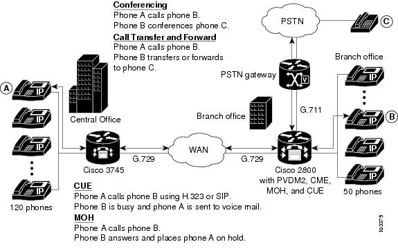
Cisco Unified CME 3.2 and later versions support transcoding between G.711 and G.729 codecs for the following features:

  • Ad hoc conferencing—One or more remote conferencing parties uses G.729.

  • Call transfer and forward—One leg of a Voice over IP (VoIP)-to-VoIP hairpin call uses G.711 and the other leg uses G.729. A hairpin call is an incoming call that is transferred or forwarded over the same interface from which it arrived.

  • Cisco Unity Express or Cisco Unity Express Virtual—An H.323 or SIP call using G.729 is forwarded to Cisco Unity Express or Cisco Unity Express Virtual. Cisco Unity Express or Cisco Unity Express Virtual supports only G.711, so G.729 must be transcoded.

    From Cisco Unified CME Release 11.6 onwards, SIP calls coming to Cisco Unity Express or Cisco Unity Express Virtual is supported on Cisco 4000 Series ISR routers using the LTI transcoding infrastructure. For more information on configuring LTI transcoding on Cisco Unified CME, see Configure LTI-based Transcoding.

  • Music on hold (MOH)—The phone receiving MOH is part of a system that uses G.729, G.722, or internet Low Bitrate Codec (iLBC). When the G.711 MOH is transcoded into G.729, it results in a poorer quality sound due to the lower compression of G.729. From Cisco Unified CME Release 11.7 onwards, Music on Hold is supported on Cisco 4000 Series ISR routers using the LTI transcoding infrastructure. For more information on configuring LTI transcoding on Cisco Unified CME, see Configure LTI-based Transcoding.

Each of the preceding call situations is illustrated in Three-Way Conferencing, Call Transfer and Forward, Cisco Unity Express, and MOH Between G.711 and G.729.

Figure 1. Three-Way Conferencing, Call Transfer and Forward, Cisco Unity Express, and MOH Between G.711 and G.729

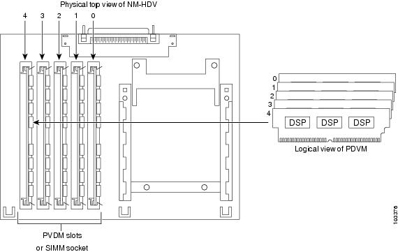
Transcoding is facilitated through DSPs, which are located in network modules. All network modules have single in-line memory module (SIMM) sockets or packet voice/data modules (PVDM) slots that each hold a Packet Voice DSP Module (PVDM). Each PVDM holds DSPs. A router can have multiple network modules.

Cisco Unified CME routers and external voice routers on the same LAN must be configured with digital signal processors (DSPs) that support transcoding. DSPs reside either directly on a voice network module, such as the NM-HD-2VE, on PVDM2s that are installed in a voice network module, such as the NM-HDV2, or on PVDM2s that are installed directly onto the motherboard, such as on the Cisco 2800 and 3800 series voice gateway routers.

  • DSPs on the NM-HDV, NM-HDV2, NM-HD-1V, NM-HD-2V, and NM-HD-2VE can be configured for transcoding.

  • PVDM2-xx on the Cisco 2800 series and the Cisco 3800 series motherboards can also be configured for transcoding.

Transcoding of G.729 calls to G.711 allows G.729 calls to participate in existing G.711 software-based, three-party conferencing, thus eliminating the need to divide DSPs between transcoding and conferencing.

NM-HDV Supports up to Five PVDMs shows an NM-HDV with five SIMM sockets or PVDM slots that each hold a 12-Channel PVDM (PVDM-12). Each PVDM-12 holds three TI 549 DSPs. Each DSP supports four channels.

Figure 2. NM-HDV Supports up to Five PVDMs

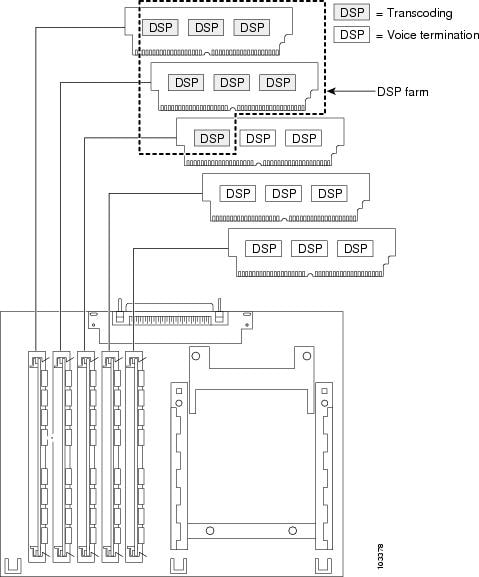
Use DSP resources to provide voice termination of the digital voice trunk group or resources for a DSP farm. DSP resources available for transcoding and not used for voice termination are referred to as a DSP farm. DSP Farm shows a DSP farm managed by Cisco Unified CME.

Figure 3. DSP Farm

Local Transcoding Interface (LTI) Based Transcoding

From Cisco Unified CME Release 11.6 onwards, Local Transcoding Interface (LTI) based transcoding is supported on Cisco 4000 series ISR. LTI includes an internal API that accesses digital signal processor (DSP) resources. This API does not require the use of Skinny Client Control Protocol (SCCP) based configuration for transcoding to work.

LTI-based transcoding is an alternative to SCCP-based transcoding. The LTI-based transcoding configures transcoding functionality only on the specific Unified CME router. Unlike the SCCP-based transcoding, other Unified CME routers cannot leverage the transcoding capabilities configured on a specific Unified CME router. That is, transcoding resources (DSPFARM) are required to be co-located with Unified CME router for LTI-based configuration to work. When both LTI-based and SCCP-based transcoding are configured, LTI takes precedence.

With LTI-based transcoding, internal APIs are used to access DSP resources for transcoding. The TCP sockets are not opened and no registration is used. Also, you need to configure only the DSPFARM profile configuration.

Voice Class Codec (VCC) is supported with LTI-based Transcoding on Cisco 4000 Series ISR, and is an optional configuration. A VCC defines the codec preference order. When a voice class codec is applied to a dial peer, the preference order defined in the voice class codec is followed.

LTI infrastructure supports the features SIP-to-SIP line to trunk transcoding, DTMF Interworking (with in-band on the trunk and rtp-nte on the line), and mid-call transcoder invocation and deletion with call transfer. Features such as Shared Line, Call Park, Call Pickup, iDivert, and so on are not supported with LTI-based transcoding.

Transcoding When a Remote Phone Uses G.729r8

A situation in which transcoding resources may be used is when you use the codec command to select the G.729r8 codec to help save network bandwidth for a remote IP phone. If a conference is initiated, all phones in the conference switch to G.711 mu-law. To allow the phone to retain its G.729r8 codec setting when joined to a conference, you can use the codec g729r8 dspfarm-assist command to specify that this phone’s calls should use the resources of a DSP farm for transcoding. For example, there are two remote phones (A and B) and a local phone (C) that initiates a conference with them. Both A and B are configured to use the G.729r8 codec with the assistance of the DSP-farm transcoder. In the conference, the call leg from C to the conference uses the G.711 mu-law codec, and the call legs from A and B to the Cisco Unified CME router use the G.729r8 codec.

Consider your options carefully when deciding to use the codec g729r8 dspfarm-assist command. The benefit is that it allows calls to use the G.729r8 codec on the call leg between the IP phone and the Cisco Unified CME router, which saves network bandwidth. The disadvantage is that for situations requiring G.711 codecs, such as conferencing and Cisco Unity Express, DSP resources that are possibly scarce are used to transcode the call, and delay is introduced while voice is shuttled to and from the DSP. In addition, the overuse of this feature can mask configuration errors in the codec selection mechanisms involving dial peers and codec lists.

Therefore, we recommend using the codec g729r8 dspfarm-assist command sparingly and only when absolutely required for bandwidth savings or when you know the phone will be participating very little, if at all, in calls that require a G.711 codec.

Because of how Cisco Unified CME uses voice channels with Skinny Client Control Protocol (SCCP) endpoints, you must configure at least two available transcoding sessions when establishing a call that requires transcoding configured with the codec g729r8 dspfarm-assist command. Only one session is used after the voice path is established with transcoding. However, during the SCCP manipulations, a temporary session may be allocated. If this temporary session cannot be allocated, the transcoding request is not honored, and the call continues with the G.711 codec.

If the codec g729r8 dspfarm-assist command is configured for a phone and a DSP resource is not available when needed for transcoding, a phone registered to the local Cisco Unified CME router will use G.711 instead of G.729r8. This is not true for nonSCCP call legs; if DSP resources are not available for the transcoding required for a conference, for example, the conference is not created.

Secure DSP Farm Transcoding

Cisco Unified CME uses the secure transcoding DSP farm capability only in the case described in Transcoding When a Remote Phone Uses G.729r8. If a call using the codec g729r8 dspfarm-assist command is secure, Cisco Unified CME looks for a secure transcoding resource. If it cannot find one, transcoding is not done. If the call is not secure, Cisco Unified CME looks for a nonsecure transcoding resource. If it cannot find one, Cisco Unified CME looks for a secure transcoding resource. Even if Cisco Unified CME uses a secure transcoding resource, the call is not secure, and a more expensive secure DSP Farm resource is not needed for a nonsecure call because Cisco Unified CME cannot find a less expensive nonsecure transcoder.

Configure Transcoding Resources

This section contains the following tasks:

Determine DSP Resource Requirements for Transcoding

To determine if that there are enough DSPs available on your router for transcoding services, perform the following steps.

Procedure


Step 1

Use the show voice dsp command to display current status of digital signal processor (DSP) voice channels.

Step 2

Use the show sdspfarm sessions command to display the number of transcoder sessions that are active.

Step 3

Use the show sdspfarm units command to display the number of DSP farms that are configured.


Provision Network Modules or PVDMs for Transcoding

DSPs can reside directly on any one of the following:

  • A voice network module, such as the NM-HD-2VE,

  • PVDM2s that are installed in a voice network module, such as the NM-HDV2. A single network module can hold up to five PVDMs.

  • PVDM2s that are installed directly onto the motherboard, such as on the Cisco 2800 and 3800 series voice gateway routers.

You must determine the number of PVDM2s or network modules that are required to support your conferencing and transcoding services and install the modules on your router.

SUMMARY STEPS

  1. Determine performance requirements.

  2. Determine the number of DSPs that are required.

  3. Determine the number of DSPs that are supportable

  4. Verify your solution.

  5. Install hardware.

DETAILED STEPS

Procedure


Step 1

Determine the number of transcoding sessions that your router must support.

Step 2

Determine the number of DSPs that are required to support transcoding sessions. See Table 5 and Table 6 in the “Allocation of DSP Resources” section of the “Configuring Enhanced Conferencing and Transcoding for Voice Gateway Routers” chapter of the Cisco Unified Communications Manager and Cisco IOS Interoperability Guide.

If voice termination is also required, determine the additional number of DSPs required.

For example: 16 transcoding sessions (30-ms packetization) and 4 G.711 voice calls require two DSPs.

Step 3

Determine the maximum number of NMs or NM farms that your router can support by using Table 4 in the “Allocation of DSP Resources” section of the “Configuring Enhanced Conferencing and Transcoding for Voice Gateway Routers” chapter of the Cisco Unified Communications Manager and Cisco IOS Interoperability Guide.

Step 4

Ensure that your requirements fall within router capabilities, taking into account whether your router supports multiple NMs or NM farms. If necessary, reassess performance requirement.

Step 5

Install PVDMs, NMs, and NM farms as needed. See the Connecting Voice Network Modules chapter in the Cisco Network Modules Hardware Installation Guide.


What to do next

Perform one of the following options, depending on the type of network module to be configured:

Configure DSP Farms for NM-HDs and NM-HDV2s

SUMMARY STEPS

  1. enable
  2. configure terminal
  3. voice-card slot
  4. dsp services dspfarm
  5. exit
  6. sccp local interface-type interface-number
  7. sccp ccm ip-address identifier identifier-number
  8. sccp
  9. sccp ccm group group-number
  10. bind interface interface-type interface-number
  11. associate ccm identifier-number priority priority-number
  12. associate profile profile identifier register device-name
  13. keepalive retries number
  14. switchover method [ graceful | immediate]
  15. switch back method { graceful | guard timeout-guard-value | immediate | uptime uptime-timeout-value}
  16. switchback interval seconds
  17. exit
  18. dspfarm profile profile-identifier transcode [ security]
  19. trustpoint trustpoint-label
  20. codec codec-type
  21. maximum sessions number
  22. associate application sccp
  23. end

DETAILED STEPS

  Command or Action Purpose

Step 1

enable

Example:

Router> enable

Enables privileged EXEC mode.

  • Enter your password if prompted.

Step 2

configure terminal

Example:

Router# configure terminal

Enters global configuration mode.

Step 3

voice-card slot

Example:

Router(config)# voice-card 1

Enters voice-card configuration mode for the network module on which you want to enable DSP-farm services.

Step 4

dsp services dspfarm

Example:

Router(config-voicecard)# dsp services dspfarm

Enables DSP-farm services for the voice card.

Step 5

exit

Example:

Router(config-voicecard)# exit

Exits voice-card configuration mode.

Step 6

sccp local interface-type interface-number

Example:

Router(config)# sccp local FastEthernet 0/0

Selects the local interface that the SCCP applications (transcoding and conferencing) should use to register with Cisco Unified CME.

  • interface-type —Interface type that the SCCP application uses to register with Cisco Unified CME. The type can be an interface address or a virtual-interface address such as Ethernet.

  • interface-number —Interface number that the SCCP application uses to register with Cisco Unified CME.

Step 7

sccp ccm ip-address identifier identifier-number

Example:

Router(config)# sccp ccm 10.10.10.1 identifier 1

Specifies the Cisco Unified CME address.

  • ip-address —IP address of the Cisco Unified CME router.

  • identifier identifier-number —Number that identifies the Cisco Unified CME router.

  • Repeat this step to specify the address of a secondary Cisco Unified CME router.

Step 8

sccp

Example:

Router(config)# sccp

Enables SCCP and its associated transcoding and conferencing applications.

Step 9

sccp ccm group group-number

Example:

Router(config)# sccp ccm group 1

Creates a Cisco Unified CME group and enters SCCP configuration mode for Cisco Unified CME.

  • group-number —Number that identifies the Cisco Unified CME group.

Note


A Cisco Unified CME group is a naming device under which data for the DSP farms is declared. Only one group is required.

Step 10

bind interface interface-type interface-number

Example:

Router(config-sccp-ccm)# bind interface FastEthernet 0/0

(Optional) Binds an interface to a Cisco Unified CME group so that the selected interface is used for all calls that belong to the profiles that are associated to this Cisco Unified CME group.

  • This command is optional, but we recommend it if you have more than one profile or if you are on different subnets, to ensure that the correct interface is selected.

Step 11

associate ccm identifier-number priority priority-number

Example:

Router(config-sccp-ccm)# associate ccm 1 priority 1

Associates a Cisco Unified CME router with a group and establishes its priority within the group.

  • identifier-number —Number that identifies the Cisco Unified CME router. See the sccp ccm command in Step 7.

  • priority —The priority of the Cisco Unified CME router in the Cisco Unified CME group. Only one Cisco Unified CME group is possible. Default: 1.

Step 12

associate profile profile identifier register device-name

Example:

Router(config-sccp-ccm)# associate profile 1 register mtp000a8eaca80

Associates a DSP farm profile with a Cisco Unified CME group.

  • profile-identifier —Number that identifies the DSP farm profile.

  • device-name —MAC address with the “mtp” prefix added, where the MAC address is the burnt-in address of the physical interface that is used to register as the SCCP device.

Step 13

keepalive retries number

Example:

Router(config-sccp-ccm)# keepalive retries 5

Sets the number of keepalive retries from SCCP to Cisco Unified CME.

  • number —Number of keepalive attempts. Range: 1 to 32. Default: 3.

Step 14

switchover method [ graceful | immediate]

Example:

Router(config-sccp-ccm)# switchover method immediate

Sets the switchover method that the SCCP client uses when its communication link to the active Cisco Unified CME system goes down.

  • graceful —Switchover happens only after all the active sessions have been terminated gracefully.

  • immediate —Switches over to any one of the secondary Cisco Unified CME systems immediately.

Step 15

switch back method { graceful | guard timeout-guard-value | immediate | uptime uptime-timeout-value}

Example:

Router(config-sccp-ccm)# switchback method immediate

Sets the switch back method that the SCCP client uses when the primary or higher priority Cisco Unified CME becomes available again.

  • graceful —Switchback happens only after all the active sessions have been terminated gracefully.

  • guard timeout-guard-value —Switchback happens either when the active sessions have been terminated gracefully or when the guard timer expires, whichever happens first. Timeout value is in seconds. Range: 60 to 172800. Default: 7200.

  • immediate —Switches back to the higher order Cisco Unified CME immediately when the timer expires, whether there is an active connection or not.

  • uptime uptime-timeout-value —Initiates the uptime timer when the higher-order Cisco Unified CME system comes alive. Timeout value is in seconds. Range: 60 to 172800. Default: 7200.

Step 16

switchback interval seconds

Example:

Router(config-sccp-ccm)# switchback interval 5

Sets the amount of time that the DSP farm waits before polling the primary Cisco Unified CME system when the current Cisco Unified CME switchback connection fails.

  • seconds —Timer value, in seconds. Range: 1 to 3600. Default: 60.

Step 17

exit

Example:

Router(config-sccp-ccm)# exit

Exits SCCP configuration mode.

Step 18

dspfarm profile profile-identifier transcode [ security]

Example:

Router(config)# dspfarm profile 1 transcode security

Enters DSP farm profile configuration mode and defines a profile for DSP farm services.

  • profile-identifier —Number that uniquely identifies a profile. Range: 1 to 65535.

  • transcode —Enables profile for transcoding.

  • security —Enables secure DSP farm services. This keyword is supported in Cisco Unified CME 4.2 and later versions.

Step 19

trustpoint trustpoint-label

Example:

Router(config-dspfarm-profile)# trustpoint dspfarm

(Optional) Associates a trustpoint with a DSP farm profile.

Step 20

codec codec-type

Example:

Router(config-dspfarm-profile)# codec g711ulaw 

Specifies the codecs supported by a DSP farm profile.

  • codec-type —Specifies the preferred codec. Type ? for a list of supported codecs.

  • Repeat this step for each supported codec.

Step 21

maximum sessions number

Example:

Router(config-dspfarm-profile)# maximum sessions 5

Specifies the maximum number of sessions that are supported by the profile.

  • number —Number of sessions supported by the profile. Range: 0 to X. Default: 0.

  • The X value is determined at run time depending on the number of resources available with the resource provider.

Step 22

associate application sccp

Example:

Router(config-dspfarm-profile)# associate application sccp

Associates SCCP with the DSP farm profile.

Step 23

end

Example:

Router(config-dspfarm-profile)# end

Returns to privileged EXEC mode.

What to do next

Configure DSP Farms for NM-HDVs

SUMMARY STEPS

  1. enable
  2. configure terminal
  3. voice-card slot
  4. dsp services dspfarm
  5. exit
  6. sccp local interface-type interface-number
  7. sccp ccm ip-address priority priority-number
  8. sccp
  9. dsp farm transcoder maximum sessions number
  10. dspfarm
  11. end

DETAILED STEPS

  Command or Action Purpose

Step 1

enable

Example:

Router> enable

Enables privileged EXEC mode.

  • Enter your password if prompted.

Step 2

configure terminal

Example:

Router# configure terminal

Enters global configuration mode.

Step 3

voice-card slot

Example:

Router(config)# voice-card 1

Enters voice-card configuration mode and identifies the slot in the chassis in which the NM-HDV or NM-HDV farm is located.

Step 4

dsp services dspfarm

Example:

Router(config-voicecard)# dsp services dspfarm

Enables DSP-farm services on the NM-HDV or NM-HDV farm.

Step 5

exit

Example:

Router(config-voicecard)# exit

Returns to global configuration mode.

Step 6

sccp local interface-type interface-number

Example:

Router(config)# sccp local FastEthernet 0/0

Selects the local interface that the SCCP applications (transcoding and conferencing) should use to register with Cisco Unified CME.

  • interface-type —Interface type that the SCCP application uses to register with Cisco Unified CME. The type can be an interface address or a virtual-interface address such as Ethernet.

  • interface-number —Interface number that the SCCP application uses to register with Cisco Unified CME.

Step 7

sccp ccm ip-address priority priority-number

Example:

Router(config)# sccp ccm 10.10.10.1 priority 1

Specifies the Cisco Unified CME address.

  • ip-address —IP address of the Cisco Unified CME router.

  • priority priority —Priority of the Cisco Unified CME router relative to other connected routers. Range: 1 (highest) to 4 (lowest).

Step 8

sccp

Example:

Router(config)# sccp

Enables SCCP and its associated transcoding and conferencing applications.

Step 9

dsp farm transcoder maximum sessions number

Example:

Router(config)# dspfarm transcoder maximum sessions 12

Specifies the maximum number of transcoding sessions to be supported by the DSP farm. A DSP can support up to four transcoding sessions.

Note


When you assign this value, take into account the number of DSPs allocated for conferencing services.

Step 10

dspfarm

Example:

Router(config)# dspfarm

Enables the DSP farm.

Step 11

end

Example:

Router(config)# end

Returns to privileged EXEC mode.

Configure the Cisco Unified CME Router to Act as the DSP Farm Host

Determine the Maximum Number of Transcoder Sessions

To determine the maximum number of transcoder sessions that can occur at one time perform the following steps.

Procedure

Step 1

Use the dspfarm transcoder maximum sessions command to set the maximum number of transcoder sessions you have configured.

Step 2

Use the show sdspfarm sessions command to display the number of transcoder sessions that are active.

Step 3

Use the show sdspfarm units command to display the number of DSP farms that are configured.

Step 4

Obtain the maximum number of transcoder sessions by multiplying the number of transcoder sessions from Step 2 (configured in Step 1 using the dspfarm transcoder maximum sessions command) by the number of DSP farms from Step 3.


Set the Cisco Unified CME Router to Receive IP Phone Messages


Note


You can unregister all active calls’ transcoding streams with the sdspfarm unregister force command.


Before you begin

Identify the MAC address of the SCCP client interface. For example, if you have the following configuration:

interface FastEthernet 0/0
 ip address 10.5.49.160 255.255.0.0
 .
 .
 .
sccp local FastEthernet 0/0
 sccp

The show interface FastEthernet 0/0 command will yield a MAC address. In the following example, the MAC address of the Fast Ethernet interface is 000a.8aea.ca80:

Router# show interface FastEthernet 0/0 
.
.
.
FastEthernet0/0 is up, line protocol is up
Hardware is AmdFE, address is 000a.8aea.ca80 (bia 000a.8aea.ca80) 

SUMMARY STEPS

  1. enable
  2. configure terminal
  3. telephony-service
  4. ip source-address ip-address [ port port] [ any-match | strict-match]
  5. sdspfarm units number
  6. sdspfarm transcode sessions number
  7. sdspfarm tag number device-name
  8. end

DETAILED STEPS

  Command or Action Purpose

Step 1

enable

Example:
Router> enable

Enables privileged EXEC mode.

  • Enter your password if prompted.

Step 2

configure terminal

Example:
Router# configure terminal

Enters global configuration mode.

Step 3

telephony-service

Example:
Router(config)# telephony-service

Enters telephony-service configuration mode.

Step 4

ip source-address ip-address [ port port] [ any-match | strict-match]

Example:
Router(config-telephony)# ip source address 10.10.10.1 port 3000

Enables a router to receive messages from Cisco Unified IP phones through the router's IP addresses and ports.

  • address —Range: 0 to 5. Default: 0.

  • port port —(Optional) TCP/IP port used for SCCP. Default: 2000.

  • any-match —(Optional) Disables strict IP address checking for registration. This is the default.

  • strict-match —(Optional) Requires strict IP address checking for registration.

Step 5

sdspfarm units number

Example:
Router(config-telephony)# sdspfarm units 4

Specifies the maximum number of DSP farms that are allowed to be registered to the SCCP router.

  • number —Range: 0 to 5. Default: 0.

Step 6

sdspfarm transcode sessions number

Example:
Router(config-telephony)# sdspfarm transcode sessions 40

Specifies the maximum number of transcoder sessions for G.729 allowed by the Cisco Unified CME router.

  • One transcoder session consists of two transcoding streams between callers using transcode. Use the maximum number of transcoding sessions and conference calls that you want your router to support at one time.

  • number —See Determine the Maximum Number of Transcoder Sessions. Range: 0 to 128. Default: 0.

Step 7

sdspfarm tag number device-name

Example:
Router(config-telephony)# sdspfarm tag 1 mtp000a8eaca80

or

Router(config-telephony)# sdspfarm tag 1 MTP000a8eaca80

Permits a DSP farm unit to be registered to Cisco Unified CME and associates it with an SCCP client interface's MAC address.

  • Required only if you blocked automatic registration by using the auto-reg-ephone command.

  • number —The tag number. Range: 1 to 5.

  • device-name —MAC address of the SCCP client interface with the "MTP" prefix added.

Step 8

end

Example:
Router(config-telephony)# end

Returns to privileged EXEC mode.

Configure the Cisco Unified CME Router to Host a Secure DSP Farm

You must configure the Media Encryption Secure Real-Time Transport Protocol (SRTP) feature in the Cisco Unified CME 4.2 and later versions, making it a secure Cisco Unified CME, before it can host a secure DSP farm. For information on configuring a secure Cisco Unified CME, see Configure Security.

Modify DSP Farms for NM-HDVs After Upgrading Cisco IOS Software

To ensure continued support for existing DSP farms for NM-HDVs configured after upgrading the Cisco IOS software on your Cisco router, perform the following steps.


Note


Perform this task if previously-configured DSP farms for NM-HDVs fail to register to Cisco Unified CME after you upgrade the Cisco IOS software release.


Before you begin

Confirm that device name for a dspfarm tag in telephony-service configuration is lower case by using the show -running configuration command.

Example:

Router#show-running configuration 
Building configuration...
.
.
.
!
telephony-service
 max-ephones 2
 max-dn 20
 ip source-address 142.103.66.254 port 2000
 auto assign 1 to 2
 system message Your current options
 sdspfarm units 2
 sdspfarm transcode sessions 16
 sdspfarm tag 1 mtp00164767cc20  !<===Device name is MAC address with lower-case “mtp” prefix 
.
.
. 
		

SUMMARY STEPS

  1. enable
  2. configure terminal
  3. no sdspfarm tag number
  4. sdspfarm tag number device-name
  5. dspfarm
  6. end

DETAILED STEPS

  Command or Action Purpose

Step 1

enable

Example:

Router> enable

Enables privileged EXEC mode.

  • Enter your password if prompted.

Step 2

configure terminal

Example:

Router# configure terminal

Enters global configuration mode.

Step 3

no sdspfarm tag number

Example:

Router(config)# no sdspfarm tag 1

Disables the DSP farm.

Step 4

sdspfarm tag number device-name

Example:

Router(config)# sdspfarm tag 1 MTP00164767cc20

Permits a digital-signal-processor (DSP) farm to be to registered to Cisco Unified CME and associates it with a SCCP client interface's MAC address.

  • Required only if you blocked automatic registration by using the auto-reg-ephone command.

  • device-name —MAC address of the SCCP client interface with the "MTP" prefix added.

Step 5

dspfarm

Example:

Router(config)# dspfarm

Enables the DSP farm.

Step 6

end

Example:

Router(config)# end

Returns to privileged EXEC mode.

Modify the Number of Transcoding Sessions for NM-HDVs

SUMMARY STEPS

  1. enable
  2. configure terminal
  3. no dspfarm
  4. dspfarm transcoder maximum sessions number
  5. dspfarm
  6. end

DETAILED STEPS

  Command or Action Purpose

Step 1

enable

Example:

Router> enable

Enables privileged EXEC mode.

  • Enter your password if prompted.

Step 2

configure terminal

Example:

Router# configure terminal

Enters global configuration mode.

Step 3

no dspfarm

Example:

Router(config)# no dspfarm

Disables the DSP farm.

Step 4

dspfarm transcoder maximum sessions number

Example:

Router(config)# dspfarm transcoder maximum sessions 12

Specifies the maximum number of transcoding sessions to be supported by the DSP farm.

Step 5

dspfarm

Example:

Router(config)# dspfarm

Enables the DSP farm.

Step 6

end

Example:

Router(config)# end

Returns to privileged EXEC mode.

Tune DSP-Farm Performance on an NM-HDV

SUMMARY STEPS

  1. enable
  2. configure terminal
  3. sccp ip precedence value
  4. dspfarm rtp timeout seconds
  5. dspfarm connection interval seconds
  6. end

DETAILED STEPS

  Command or Action Purpose

Step 1

enable

Example:

Router> enable

Enables privileged EXEC mode.

  • Enter your password if prompted.

Step 2

configure terminal

Example:

Router# configure terminal

Enters global configuration mode.

Step 3

sccp ip precedence value

Example:

Router(config)# sccp ip precedence 5

(Optional) Sets the IP precedence value to increase the priority of voice packets over connections controlled by SCCP.

Step 4

dspfarm rtp timeout seconds

Example:

Router(config)# dspfarm rtp timeout 60

(Optional) Configures the Real-Time Transport Protocol (RTP) timeout interval if the error condition "RTP port unreachable" occurs.

Step 5

dspfarm connection interval seconds

Example:

Router(config)# dspfarm connection interval 60

(Optional) Specifies how long to monitor RTP inactivity before deleting an RTP stream.

Step 6

end

Example:

Router(config)# end

Returns to privileged EXEC mode.

Verify DSP Farm Operation

To verify that the DSP farm is registered and running, perform the following steps in any order.

Procedure


Step 1

Use the show sccp [ statistics | connections] command to display the SCCP configuration information and current status.

Example:

Router# show sccp statistics 
SCCP Application Service(s) Statistics:

Profile ID:1, Service Type:Transcoding
TCP packets rx 7, tx 7
Unsupported pkts rx 1, Unrecognized pkts rx 0
Register tx 1, successful 1, rejected 0, failed 0
KeepAlive tx 0, successful 0, failed 0
OpenReceiveChannel rx 2, successful 2, failed 0
CloseReceiveChannel rx 0, successful 0, failed 0
StartMediaTransmission rx 2, successful 2, failed 0
StopMediaTransmission rx 0, successful 0, failed 0
Reset rx 0, successful 0, failed 0
MediaStreamingFailure rx 0
Switchover 0, Switchback 0

Use the show sccp connections command to display information about the connections controlled by the SCCP transcoding and conferencing applications. In the following example, the secure value of the stype field indicates that the connection is encrypted:

Router# show sccp connections 

sess_id    conn_id    	stype        		  mode     codec  ripaddr      rport sport

16777222   16777409   secure -xcode sendrecv g729b 10.3.56.120   16772 19534
16777222   16777393   secure -xcode sendrecv g711u 10.3.56.50    17030 18464
Total number of active session(s) 1, and connection(s) 2

Step 2

Use the show sdspfarm units command to display the configured and registered DSP farms.

Example:


Router# show sdspfarm units
 
mtp-1 Device:MTP003080218a31 TCP socket:[2]  REGISTERED
actual_stream:8 max_stream 8 IP:10.10.10.3  11470  MTP YOKO keepalive 1  
Supported codec:G711Ulaw
                 G711Alaw
                 G729a
                 G729ab
 
 max-mtps:1, max-streams:40, alloc-streams:8, act-streams:2

Step 3

Use the show sdspfarm sessions command to display the transcoding streams.

Example:

Router# show sdspfarm sessions 
Stream-ID:1 mtp:1 10.10.10.3  18404  Local:2000 START  
 usage:Ip-Ip                        
 codec:G711Ulaw64k  duration:20 vad:0 peer Stream-ID:2 
 
Stream-ID:2 mtp:1 10.10.10.3  17502  Local:2000 START  
 usage:Ip-Ip                        
 codec:G729AnnexA  duration:20 vad:0 peer Stream-ID:1 
 
Stream-ID:3 mtp:1 0.0.0.0  0  Local:0 IDLE   
 usage:                             
 codec:G711Ulaw64k  duration:20 vad:0 peer Stream-ID:0 
 
Stream-ID:4 mtp:1 0.0.0.0  0  Local:0 IDLE   
 usage:                             
 codec:G711Ulaw64k  duration:20 vad:0 peer Stream-ID:0 
 
Stream-ID:5 mtp:1 0.0.0.0  0  Local:0 IDLE   
 usage:                             
 codec:G711Ulaw64k  duration:20 vad:0 peer Stream-ID:0 
 
Stream-ID:6 mtp:1 0.0.0.0  0  Local:0 IDLE   
 usage:                             
 codec:G711Ulaw64k  duration:20 vad:0 peer Stream-ID:0 
 
Stream-ID:7 mtp:1 0.0.0.0  0  Local:0 IDLE   
 usage:                             
 codec:G711Ulaw64k  duration:20 vad:0 peer Stream-ID:0 
 
Stream-ID:8 mtp:1 0.0.0.0  0  Local:0 IDLE   
 usage:                             
 codec:G711Ulaw64k  duration:20 vad:0 peer Stream-ID:0

Step 4

Use the show sdspfarm sessions summary command to display a summary view the transcoding streams.

Example:

Router# show sdspfarm sessions summary
 
max-mtps:2, max-streams:240, alloc-streams:40, act-streams:2
  ID   MTP  State      CallID confID Usage                         Codec/Duration
==== ===== ====== =========== ====== ============================= ==============
1    2     IDLE   -1          0                                   G711Ulaw64k /20ms
2    2     IDLE   -1          0                                   G711Ulaw64k /20ms
3    2     START  -1          3      MoH  (DN=3  , CH=1) FE=TRUE  G729 /20ms
4    2     START  -1          3      MoH  (DN=3  , CH=1) FE=FALSE G711Ulaw64k /20ms
5    2     IDLE   -1          0                                   G711Ulaw64k /20ms
6    2     IDLE   -1          0                                   G711Ulaw64k /20ms
7    2     IDLE   -1          0                                   G711Ulaw64k /20ms
8    2     IDLE   -1          0                                   G711Ulaw64k /20ms
9    2     IDLE   -1          0                                   G711Ulaw64k /20ms
10   2     IDLE   -1          0                                   G711Ulaw64k /20ms
11   2     IDLE   -1          0                                   G711Ulaw64k /20ms
12   2     IDLE   -1          0                                   G711Ulaw64k /20ms
13   2     IDLE   -1          0                                   G711Ulaw64k /20ms
14   2     IDLE   -1          0                                   G711Ulaw64k /20ms
15   2     IDLE   -1          0                                   G711Ulaw64k /20ms
16   2     IDLE   -1          0                                   G711Ulaw64k /20ms
17   2     IDLE   -1          0                                   G711Ulaw64k /20ms
18   2     IDLE   -1          0                                   G711Ulaw64k /20ms
19   2     IDLE   -1          0                                   G711Ulaw64k /20ms
20   2     IDLE   -1          0                                   G711Ulaw64k /20ms
21   2     IDLE   -1          0                                   G711Ulaw64k /20ms
22   2     IDLE   -1          0                                   G711Ulaw64k /20ms
23   2     IDLE   -1          0                                   G711Ulaw64k /20ms
24   2     IDLE   -1          0                                   G711Ulaw64k /20ms
25   2     IDLE   -1          0                                   G711Ulaw64k /20ms
26   2     IDLE   -1          0                                   G711Ulaw64k /20ms
27   2     IDLE   -1          0                                   G711Ulaw64k /20ms
28   2     IDLE   -1          0                                   G711Ulaw64k /20ms
29   2     IDLE   -1          0                                   G711Ulaw64k /20ms
30   2     IDLE   -1          0                                   G711Ulaw64k /20ms
31   2     IDLE   -1          0                                   G711Ulaw64k /20ms
32   2     IDLE   -1          0                                   G711Ulaw64k /20ms
33   2     IDLE   -1          0                                   G711Ulaw64k /20ms
34   2     IDLE   -1          0                                   G711Ulaw64k /20ms
35   2     IDLE   -1          0                                   G711Ulaw64k /20ms
36   2     IDLE   -1          0                                   G711Ulaw64k /20ms

Step 5

Use the show sdspfarm sessions active command to display the transcoding streams for all active sessions.

Example:


Router# show sdspfarm sessions active 
 
Stream-ID:1 mtp:1 10.10.10.3  18404  Local:2000 START  
 usage:Ip-Ip                        
 codec:G711Ulaw64k  duration:20 vad:0 peer Stream-ID:2 
 
Stream-ID:2 mtp:1 10.10.10.3  17502  Local:2000 START  
 usage:Ip-Ip                        
 codec:G729AnnexA  duration:20 vad:0 peer Stream-ID:1 

Step 6

Use the show sccp connections details command to display the SCCP connections details such as call-leg details.

Example:

Router# show sccp connections details 
 
bridge-info(bid, cid) - Normal bridge information(Bridge id, Calleg id)
mmbridge-info(bid, cid) - Mixed mode bridge information(Bridge id, Calleg id)
 
sess_id    conn_id    call-id    codec   pkt-period type      bridge-info(bid, cid)   mmbridge-info(bid, cid)
 
1          -          14         N/A     N/A        transmsp  All RTPSPI Callegs      N/A                    

1          2          15         g729a   20         rtpspi    (4,14)                  N/A                    

1          1          13         g711u   20         rtpspi    (3,14)                  N/A                    

Total number of active session(s) 1, connection(s) 2, and callegs 3

Step 7

Use the debug sccp { all | errors | events | packets | parser} command to set debugging levels for SCCP and its applications.

Step 8

Use the debug dspfarm { all | errors | events | packets} command to set debugging levels for DSP-farm service.

Step 9

Use the debug ephone mtp command to enable Message Transfer Part (MTP) debugging. Use this debug command with the debug ephone mtp , debug ephone register , debug ephone state , and debug ephone pak commands.


Register the DSP Farm with Cisco Unified CME 4.2 or a Later Version in Secure Mode

The DSP farm can reside on the same router with the Cisco Unified CME or on a different router. Some of the steps in the following tasks are optional depending the location of the DSP farm.

Obtain Digital Certificate from a CA Server

The CA server can be the same router as the DSP farm. The DSP farm router can be configured as a CA server. The configuration steps below show how to configure a CA server on the DSP farm router. Additional configurations are required for configuring CA server on an external Cisco router or using a different CA server by itself.

Configure a CA Server

Note


Skip this procedure if the DSP farm resides on the same router as the Cisco Unified CME. Proceed to the Create a Trustpoint section.


The CA server automatically creates a trustpoint where the certificates are stored. The automatically created trustpoint stores the CA root certificate.

Before you begin
  • Cisco Unified CME 4.2 or a later version.

SUMMARY STEPS

  1. enable
  2. configure terminal
  3. crypto pki server label
  4. database level complete
  5. grant auto
  6. database url root-url
  7. no shutdown
  8. exit
  9. crypto pki trustpoint label
  10. revocation-check crl
  11. rsakeypair key-label

DETAILED STEPS

  Command or Action Purpose

Step 1

enable

Example:
Router> enable

Enables privileged EXEC mode.

  • Enter your password if prompted.

Step 2

configure terminal

Example:
Router# configure terminal

Enters global configuration mode.

Step 3

crypto pki server label

Example:
Router(config)# crypto pki server dspcert

Defines a label for the certificate server and enters certificate-server configuration mode.

  • label —Name for CA certificate server.

Step 4

database level complete

Example:
Router(cs-server)# database level complete

(Optional) Controls the type of data stored in the certificate enrollment database. The default if this command is not used is minimal .

  • complete —In addition to the information given in the minimal and names levels, each issued certificate is written to the database.

Note


The complete keyword produces a large amount of information; so specify an external TFTP server in which to store the data using of the database url command.

Step 5

grant auto

Example:
Router(cs-server)# grant auto

(Optional) Allows an automatic certificate to be issued to any requester. The recommended method and default if this command is not used is manual enrollment.

Tip


Use this command only during enrollment when testing and building simple networks. A security best practice is to disable this functionality using the no grant auto command after configuration so that certificates cannot be continually granted.

Step 6

database url root-url

Example:
Router(cs-server)# database url nvram:

(Optional) Specifies the location where all database entries for the certificate server are to be written out. If this command is not specified, all database entries are written to NVRAM.

  • root-url —Location where database entries will be written out. The URL can be any URL that is supported by the Cisco IOS file system.

Note


If the CA is going to issue a large number of certificates, select an appropriate storage location like flash or other storage device to store the certificates.

Note


When the storage location chosen is flash and the file system type on this device is Class B (LEFS), make sure to check free space on the device periodically and use the squeeze command to free the space used up by deleted files. This process may take several minutes and should be done during scheduled maintenance periods or off-peak hours.

Step 7

no shutdown

Example:
Router(cs-server)# no shutdown

(Optional) Enables the CA.

Note


You should use this command only after you have completely configured the CA.

Step 8

exit

Example:
Router(cs-server)# exit

Exits certificate-server configuration mode.

Step 9

crypto pki trustpoint label

Example:
Router(config)# crypto pki trustpoint dspcert

(Optional) Declares a trustpoint and enters ca-trustpoint configuration mode.

  • label —Name for the trustpoint.

Note


Use this command and the enrollment url command if this CA is local to the Cisco Unified CME router. These commands are not needed for a CA running on an external router. The label has to be the same as the label in Step 3.

Step 10

revocation-check crl

Example:
Router(ca-trustpoint)# revocation-check crl

(Optional) Checks the revocation status of a certificate and specifies one or more methods to check the status. If a second and third method are specified, each method is used only if the previous method returns an error, such as a server being down.

  • crl —Certificate checking is performed by a certificate revocation list (CRL). This is the default behavior.

Step 11

rsakeypair key-label

Example:
Router(ca-trustpoint)# rsakeypair caserver

(Optional) Specifies an RSA key pair to use with a certificate.

  • key-label —Name of the key pair, which is generated during enrollment if it does not already exist or if the auto-enroll regenerate command is used.

Note


Multiple trustpoints can share the same key.

Create a Trustpoint

The trustpoint stores the digital certificate for the DSP farm. To create a trustpoint, perform the following procedure:

Before you begin
  • Cisco Unified CME 4.2 or a later version.

SUMMARY STEPS

  1. enable
  2. configure terminal
  3. crypto pki trustpoint label
  4. enrollment url ca-url
  5. serial-number none
  6. fqdn none
  7. ip-address none
  8. subject-name [ x.500-name]
  9. revocation-check none
  10. rsakeypair key-label

DETAILED STEPS

  Command or Action Purpose

Step 1

enable

Example:
Router> enable

Enables privileged EXEC mode.

  • Enter your password if prompted.

Step 2

configure terminal

Example:
Router# configure terminal

Enters global configuration mode.

Step 3

crypto pki trustpoint label

Example:
Router(config)# crypto pki trustpoint dspcert

Declares the trustpoint that your RA mode certificate server should use and enters CA-trustpoint configuration mode.

  • label —Name for the trustpoint and RA.

Step 4

enrollment url ca-url

Example:
Router(ca-trustpoint)# enrollment url http://10.3.105.40:80

Specifies the enrollment URL of the issuing CA certificate server (root certificate server).

  • ca-url —URL of the router on which the root CA is installed.

Step 5

serial-number none

Example:
Router(ca-trustpoint)# serial-number none

Specifies whether the router serial number should be included in the certificate request.

  • none —Specifies that a serial number will not be included in the certificate request.

Step 6

fqdn none

Example:
Router(ca-trustpoint)# fqdn none

Specifies a fully qualified domain name (FQDN) that will be included as "unstructuredName" in the certificate request.

  • none —Router FQDN will not be included in the certificate request.

Step 7

ip-address none

Example:
Router(ca-trustpoint)# ip-address none

Specifies a dotted IP address or an interface that will be included as "unstructuredAddress" in the certificate request.

  • none —Specifies that an IP address is not to be included in the certificate request.

Step 8

subject-name [ x.500-name]

Example:
Router(ca-trustpoint)# subject-name cn=vg224, ou=ABU, o=Cisco Systems Inc.

Specifies the subject name in the certificate request.

Note


The example shows how to format the certificate subject name to be similar to that of an IP phones.

Step 9

revocation-check none

Example:
Router(ca-trustpoint)# revocation-check none

(Optional) Checks the revocation status of a certificate and specifies one or more methods to check the status. If a second and third method are specified, each method is used only if the previous method returns an error, such as a server being down.

  • none —Certificate checking is not required.

Step 10

rsakeypair key-label

Example:
Router(ca-trustpoint)# rsakeypair dspcert

(Optional) Specifies an RSA key pair to use with a certificate.

  • key-label —Name of the key pair, which is generated during enrollment if it does not already exist or if the auto-enroll regenerate command is used.

Note


Multiple trustpoints can share the same key. The key-label is the same as the label in Step 3.

Authenticate and Enroll a Certificate with the CA Server
Before you begin
  • Cisco Unified CME 4.2 or a later version.

SUMMARY STEPS

  1. enable
  2. configure terminal
  3. crypto pki authenticate trustpoint-label
  4. crypto pki enroll trustpoint-label

DETAILED STEPS

  Command or Action Purpose

Step 1

enable

Example:
Router> enable

Enables privileged EXEC mode.

  • Enter your password if prompted.

Step 2

configure terminal

Example:
Router# configure terminal

Enters global configuration mode.

Step 3

crypto pki authenticate trustpoint-label

Example:
Router(config)# crypto pki authenticate dspcert

Retrieves the CA certificate and authenticates it. Checks the certificate fingerprint if prompted.

  • trustpoint-label —Trustpoint label.

Note


The trustpoint-label is the trustpoint label specified in the Create a Trustpoint section.

Step 4

crypto pki enroll trustpoint-label

Example:
Router(config)# crypto pki enroll dspcert

Enrolls with the CA and obtains the certificate for this trustpoint.

  • trustpoint-label —Trustpoint label.

Note


The trustpoint-label is the trustpoint label specified in the Create a Trustpoint section.

Copy the CA Root Certificate of the DSP Farm Router to the Cisco Unified CME Router

The DSP farm router and Cisco Unified CME router exchanges certificates during the registration process. These certificates are digitally signed by the CA server of the respective router. For the routers to accept each others digital certificate, they should have the CA root certificate of each other. Manually copy the CA root certificate of the DSP farm and Cisco Unified CME router to each other.

Before you begin
  • Cisco Unified CME 4.2 or a later version.

SUMMARY STEPS

  1. enable
  2. configure terminal
  3. crypto pki trustpoint label
  4. enrollment terminal
  5. crypto pki export trustpoint pem terminal
  6. crypto pki authenticate trustpoint-label
  7. You will be prompted to enter the CA certificate. Cut and paste the base 64 encoded certificate at the command line, then press Enter, and type "quit". The router prompts you to accept the certificate. Enter "yes" to accept the certificate.

DETAILED STEPS

  Command or Action Purpose

Step 1

enable

Example:
Router> enable

Enables privileged EXEC mode.

  • Enter your password if prompted.

Step 2

configure terminal

Example:
Router# configure terminal

Enters global configuration mode.

Step 3

crypto pki trustpoint label

Example:
Router(config)# crypto pki trustpoint dspcert

Declares the trustpoint that your RA mode certificate server should use and enters CA-trustpoint configuration mode.

  • label —Name for the trustpoint and RA.

Note


The label is the trustpoint label specified in the Create a Trustpoint section.

Step 4

enrollment terminal

Example:
Router(ca-trustpoint)# enrollment terminal

Specifies manual cut-and-paste certificate enrollment.

Step 5

crypto pki export trustpoint pem terminal

Example:
Router(ca-trustpoint)# crypto pki export dspcert pem terminal

Exports certificates and RSA keys that are associated with a trustpoint in a privacy-enhanced mail (PEM)-formatted file.

Step 6

crypto pki authenticate trustpoint-label

Example:
Router(config)# crypto pki authenticate vg224

Retrieves the CA certificate and authenticates it. Checks the certificate fingerprint if prompted.

  • trustpoint-label —Trustpoint label.

Note


This command is optional if the CA certificate is already loaded into the configuration.

Step 7

You will be prompted to enter the CA certificate. Cut and paste the base 64 encoded certificate at the command line, then press Enter, and type "quit". The router prompts you to accept the certificate. Enter "yes" to accept the certificate.

Completes the copying of the CA root certificate of the DSP farm router to the Cisco Unified CME router.

Configure Cisco Unified CME to Allow the DSP Farm to Register

Before you begin
  • Cisco Unified CME 4.2 or a later version.

SUMMARY STEPS

  1. enable
  2. configure terminal
  3. telephony-service
  4. sdspfarm units number
  5. sdspfarm transcode sessions number
  6. sdspfarm tag number device-name
  7. exit

DETAILED STEPS

  Command or Action Purpose

Step 1

enable

Example:
Router> enable

Enables privileged EXEC mode.

  • Enter your password if prompted.

Step 2

configure terminal

Example:
Router# configure terminal

Enters global configuration mode.

Step 3

telephony-service

Example:
Router(config)# telephony-service

Enters telephony-service configuration mode.

Step 4

sdspfarm units number

Example:
Router(config-telephony)# sdspfarm units 1

Specifies the maximum number of digital-signal-processor (DSP) farms that are allowed to be registered to the Skinny Client Control Protocol (SCCP) server.

Step 5

sdspfarm transcode sessions number

Example:
Router(config-telephony)# sdspfarm transcode sessions 30

Specifies the maximum number of transcoding sessions allowed per Cisco Unified CME router.

  • number —Declares the number of DSP farm sessions. Valid values are numbers from 1 to 128.

Step 6

sdspfarm tag number device-name

Example:
Router(config-telephony)# sdspfarm tag 1 vg224

Permits a DSP farm to register to Cisco Unified CME and associates it with a SCCP client interfaces MAC address.

Note


The device-name in this step must be the same as the device-name in the associate profile command in Step 17 of the Configure DSP Farms for NM-HDs and NM-HDV2s section.

Step 7

exit

Example:
Router(config-telephony)# exit

Exits telephony-service configuration mode.

Verify DSP Farm Registration with Cisco Unified CME

Use the show sdspfarm units command to verify that the DSP farm is registering with Cisco Unified CME. Use the show voice dsp group slot command to show the status of secure conferencing.

Prerequisites

  • Cisco Unified CME 4.2 or a later version.

show sdspfarm units
Router# show sdspfarm units 

mtp-2 Device:choc2851SecCFB1 TCP socket:[1]  REGISTERED
actual_stream:8 max_stream 8 IP:10.1.0.20  37043  MTP YOKO keepalive 17391  
Supported codec: G711Ulaw
                 G711Alaw
                 G729
                 G729a
                 G729ab
                 GSM FR

 max-mtps:2, max-streams:60, alloc-streams:18, act-streams:0
 
show voice dsp

Router# show voice dsp group slot 1 

dsp 13:
  State: UP, firmware: 4.4.706
  Max signal/voice channel: 16/16
  Max credits: 240
  Group: FLEX_GROUP_VOICE, complexity: FLEX
    Shared credits: 180, reserved credits: 0
    Signaling channels allocated: 2
    Voice channels allocated: 0
    Credits used: 0
  Group: FLEX_GROUP_XCODE, complexity: SECURE MEDIUM
    Shared credits: 0, reserved credits: 60
    Transcoding channels allocated: 0
    Credits used: 0
dsp 14:
  State: UP, firmware: 1.0.6
  Max signal/voice channel: 16/16
  Max credits: 240
  Group: FLEX_GROUP_CONF, complexity: SECURE CONFERENCE
    Shared credits: 0, reserved credits: 240
    Conference session: 1
    Credits used: 0

Configure LTI-based Transcoding

SUMMARY STEPS

  1. enable
  2. configure terminal
  3. voice-card slot
  4. dsp services dspfarm
  5. exit
  6. dspfarm profile profile-identifier transcode [ universal]
  7. codec codec-type
  8. maximum sessions number
  9. associate application CUBE
  10. no shutdown
  11. end

DETAILED STEPS

  Command or Action Purpose

Step 1

enable

Example:

Router> enable

Enables privileged EXEC mode.

  • Enter your password if prompted.

Step 2

configure terminal

Example:

Router# configure terminal

Enters global configuration mode.

Step 3

voice-card slot

Example:

Router(config)# voice-card 1

Enters voice-card configuration mode for the network module on which you want to enable DSP-farm services.

Step 4

dsp services dspfarm

Example:

Router(config-voicecard)# dsp services dspfarm

Enables DSP-farm services for the voice card.

Step 5

exit

Example:

Router(config-voicecard)# exit

Exits voice-card configuration mode.

Step 6

dspfarm profile profile-identifier transcode [ universal]

Example:

Router(config)# dspfarm profile 1 transcode universal

Enters DSP farm profile configuration mode and defines a profile for DSP farm services.

  • profile-identifier —Number that uniquely identifies a profile. Range: 1 to 65535.

  • transcode —Enables profile for transcoding.

  • universal —Enables transcoding support between all codecs for DSP farm services. Without universal , transcoding is always from g711ulaw to any other codec. This keyword is supported in Cisco Unified CME 11.6 and later versions for Cisco 4000 Series ISR.

Step 7

codec codec-type

Example:

Router(config-dspfarm-profile)# codec g711ulaw 

Specifies the codecs supported by a DSP farm profile.

  • codec-type —Specifies the preferred codec. Type ? for a list of supported codecs.

  • Repeat this step for each supported codec.

Step 8

maximum sessions number

Example:

Router(config-dspfarm-profile)# maximum sessions 5

Specifies the maximum number of sessions that are supported by the profile.

  • number —Number of sessions supported by the profile. If the variable is not configured or if the DSP resources are not available, the value is set to 0.

  • The X value is determined at run time depending on the number of resources available with the resource provider.

Step 9

associate application CUBE

Example:

Router(config-dspfarm-profile)# associate application CUBE

Associates CUBE with the DSP farm profile.

Step 10

no shutdown

Example:

Router(config-dspfarm-profile)# no shutdown

Enables the DSP farm profile.

Step 11

end

Example:

Router(config-dspfarm-profile)# end

Returns to privileged EXEC mode.

What to do next


Note


You can use the command show dspfarm profile profile-number to verify the configured DSP farm profiles. Use the command to verify if the profile status is UP, and the application status is ASSOCIATED.


Configuration Examples for Transcoding Resources

Example for Setting up DSP Farms for NM-HDVs

The following example sets up a DSP farm of 4 DSPs to handle up to 16 sessions (4 sessions per DSP) on a router with an IP address of 10.5.49.160 and a priority of 1 among other servers.

voice-card 1
 dsp services dspfarm
 exit
sccp local FastEthernet 0/0
sccp
sccp ccm 10.5.49.160 priority 1
dspfarm transcoder maximum sessions 16
dspfarm

telephony-service
ip source-address 10.5.49.200 port 2000
sdspfarm units 4
sdspfarm transcode sessions  40
sdspfarm tag 1 mtp000a8eaca80
sdspfarm tag 2 mtp123445672012

Example for Setting Up DSP Farms for NM-HDs and NM-HDV2s

The following example sets up six transcoding sessions on a router with one DSP farm, an IP address of 10.5.49.160, and a priority of 1 among servers.

voice-card 1
 dsp services dspfarm

sccp local FastEthernet 0/1
sccp
sccp ccm 10.5.49.160 identifier 1

sccp ccm group 123
 associate ccm 1 priority
 associate profile 1 register mtp123456792012
 keepalive retries 5
 switchover method immediate
 switchback method immediate
switchback interval 5

dspfarm profile 1 transcode
 codec g711ulaw
 codec g711alaw
 codec g729ar8
 codec g729abr8
 maximum sessions 6
 associate application sccp

telephony-service
 ip source-address 10.5.49.200 port 2000
 sdspfarm units 1
 sdspfarm transcode sessions  40
 sdspfarm tag 1 mtp000a8eaca80
 sdspfarm tag 2 mtp123445672012

Example for Configuring Cisco Unified CME Router as the DSP Farm Host

The following example configures Cisco Unified CME router address 10.100.10.11 port 2000 to be the farm host using the DSP farm at mtp000a8eaca80 to allow for a maximum of 1 DSP farm and 16 transcoder sessions.

telephony-service
 ip source address 10.100.10.11 port 2000
 sdspfarm units 1
 sdspfarm transcode sessions 16
 sdspfarm tag 1 mtp000a8eaca80

Example for Configuring LTI-based Transcoding

The following example configures Cisco Unified CME router for LTI-based transcoding.


voice-card 0
 dsp services dspfarm
!--- Dspfarm profile configuration with associate 
!--- application CUBE for LTI transcoding.
dspfarm profile 1 transcode universal
codec g729ar8
codec g729br8
codec g711alaw
codec g711ulaw
codec g729r8
maximum sessions 12
associate application CUBE

!--- Only dspfarm profile configurations are needed for
!--- LTI-based transcoding. All the SCCP-based transcoding
!--- features will be supported with LTI-based transcoding.

Example for Configuring Voice Class Codec

The following example configures voice class codec under a dial peer on Unified CME.


voice class codec 10
 codec preference 1 g711alaw
 codec preference 2 g711ulaw bytes 80
 codec preference 3 g723ar53
 codec preference 4 g723ar63 bytes 144
 codec preference 5 g723r53
 codec preference 6 g723r63 bytes 120
 codec preference 7 g726r16
 codec preference 8 g726r24
 codec preference 9 g726r32 bytes 80
 codec preference 10 g728
 codec preference 11 g729br8
 codec preference 12 g729r8 bytes 50

dial-peer voice 100 voip
 voice-class codec 10

You can also configure voice class codec under a voice register pool on Unified CME.


voice register pool 1
 id mac 0030.94C2.A22A
 preference 5
 cor incoming call91 1 91011
 translate-outgoing called 1
 proxy 192.0.2.0 preference 1 monitor probe icmp-ping
 alias 1 94... to 91011 preference 8
 voice-class codec 10

Where to go Next

Music on Hold

Music on hold can require transcoding resources. See Music on Hold.

Teleworker Remote Phones

Transcoding has benefits and disadvantages for remote teleworker phones. See the discussion in Configuring Phones to Make Basic Calls.

Feature Information for Transcoding Resources

The following table provides release information about the feature or features described in this module. This table lists only the software release that introduced support for a given feature in a given software release train. Unless noted otherwise, subsequent releases of that software release train also support that feature.

Use Cisco Feature Navigator to find information about platform support and Cisco software image support. To access Cisco Feature Navigator, go to www.cisco.com/go/cfn. An account on Cisco.com is not required.

Table 1. Feature Information for Transcoding Resources

Feature Name

Cisco Unified CME Version

Feature Information

LTI-based Transcoding

11.6

Support for LTI-based Transcoding on Cisco 4000 Series ISR.

Secure Transcoding

4.2

Secure transcoding for calls using the codec g729r8 dspfarm-assist command was introduced.

Transcoding Support

3.2

Transcoding between G.711 and G.729 was introduced.