Konfiguration und Überprüfung von Cloud OnRamp für Multicloud - AWS
Download-Optionen
-
ePub (1.5 MB)
In verschiedenen Apps auf iPhone, iPad, Android, Sony Reader oder Windows Phone anzeigen
Inklusive Sprache
In dem Dokumentationssatz für dieses Produkt wird die Verwendung inklusiver Sprache angestrebt. Für die Zwecke dieses Dokumentationssatzes wird Sprache als „inklusiv“ verstanden, wenn sie keine Diskriminierung aufgrund von Alter, körperlicher und/oder geistiger Behinderung, Geschlechtszugehörigkeit und -identität, ethnischer Identität, sexueller Orientierung, sozioökonomischem Status und Intersektionalität impliziert. Dennoch können in der Dokumentation stilistische Abweichungen von diesem Bemühen auftreten, wenn Text verwendet wird, der in Benutzeroberflächen der Produktsoftware fest codiert ist, auf RFP-Dokumentation basiert oder von einem genannten Drittanbieterprodukt verwendet wird. Hier erfahren Sie mehr darüber, wie Cisco inklusive Sprache verwendet.
Informationen zu dieser Übersetzung
Cisco hat dieses Dokument maschinell übersetzen und von einem menschlichen Übersetzer editieren und korrigieren lassen, um unseren Benutzern auf der ganzen Welt Support-Inhalte in ihrer eigenen Sprache zu bieten. Bitte beachten Sie, dass selbst die beste maschinelle Übersetzung nicht so genau ist wie eine von einem professionellen Übersetzer angefertigte. Cisco Systems, Inc. übernimmt keine Haftung für die Richtigkeit dieser Übersetzungen und empfiehlt, immer das englische Originaldokument (siehe bereitgestellter Link) heranzuziehen.
Inhalt
Einleitung
In diesem Dokument wird die Konfiguration und Überprüfung von Cisco SD-WAN Cloud OnRamp für die Multicloud-Integration mit Amazon Web Services (AWS) beschrieben.
Voraussetzungen
Stellen Sie sicher, dass Sie über Folgendes verfügen:
- AWS Cloud-Kontodetails
- Abonnement für AWS Marketplace.
-
Der Cisco SD-WAN Manager muss über zwei verfügbare Catalyst 8000V OTP-Token verfügen, um die Cloud Gateways auf der Registerkarte "Zertifikate" erstellen zu können.
Anforderungen
Cisco empfiehlt, dass Sie über Kenntnisse in folgenden Bereichen verfügen:
- Cisco Software-defined Wide Area Network (SD-WAN)
- AWS
Verwendete Komponenten
Dieses Dokument basiert auf den folgenden Software- und Hardwareversionen:
- Cisco Catalyst SD-WAN Manager Version 20.9.4.1
- Cisco Catalyst SD-WAN Controller Version 20.9.4
- Cisco Edge Router Version 17.9.04a
Die Informationen in diesem Dokument beziehen sich auf Geräte in einer speziell eingerichteten Testumgebung. Alle Geräte, die in diesem Dokument benutzt wurden, begannen mit einer gelöschten (Nichterfüllungs) Konfiguration. Wenn Ihr Netzwerk in Betrieb ist, stellen Sie sicher, dass Sie die möglichen Auswirkungen aller Befehle kennen.
Konfigurieren
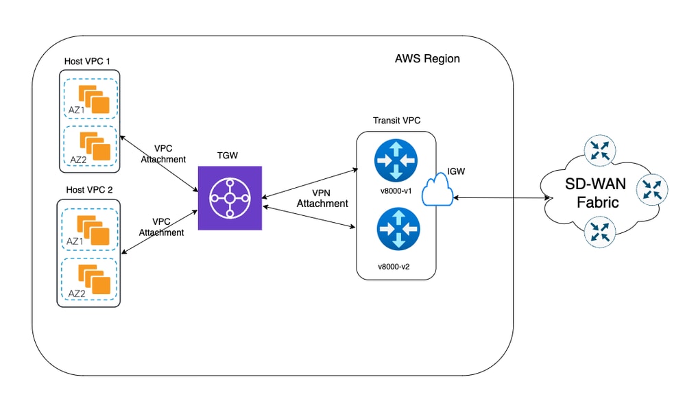
Netzwerkdiagramm
Konfigurationen
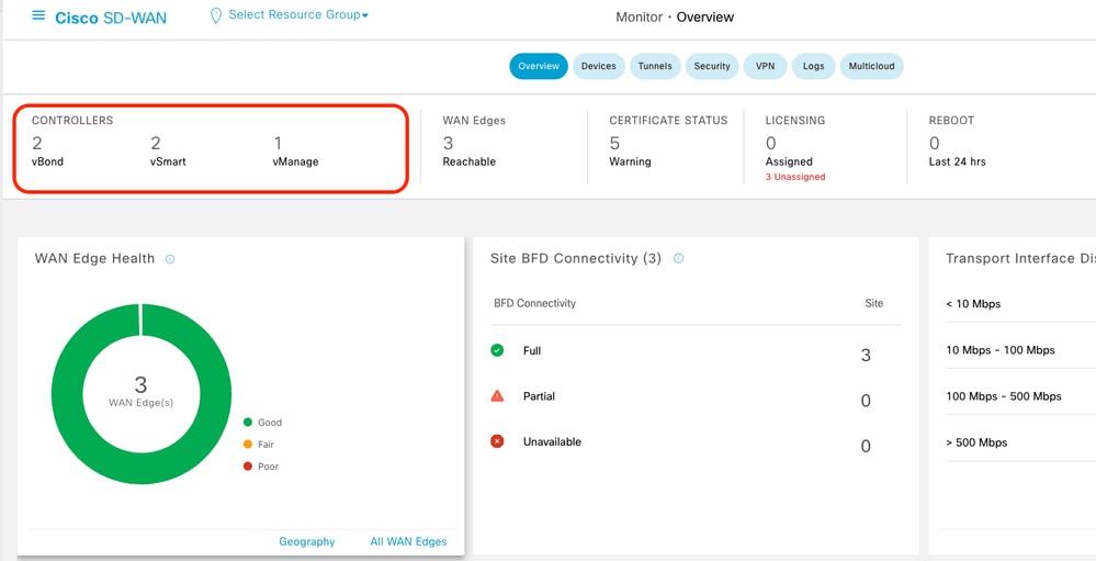
Melden Sie sich bei der Catalyst SD-WAN Manager-GUI an, und stellen Sie sicher, dass alle Controller aktiv sind.
Schritt 1: Anhängen der AWS-Gerätevorlage an zwei C8000v-Geräte
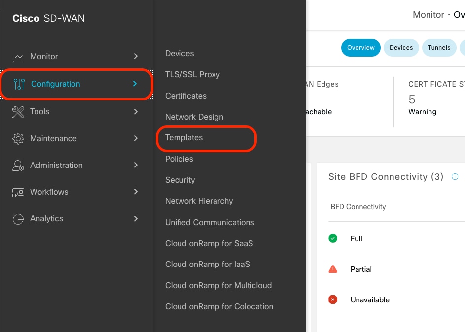
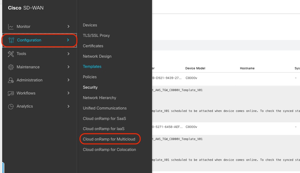
Navigieren Sie im Menü Cisco SD-WAN Manager zu Configuration > Templates (Konfiguration > Vorlagen).
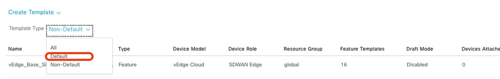
Klicken Sie auf Device Templates > From Template. Geben Sie das Dropdown-Menü ein, und wählen Sie Standard aus.
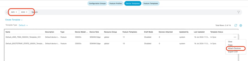
Geben Sie in die Suchleiste AWS und C8000v ein. Klicken Sie dann auf die 3 Punkte (...) neben der Vorlage Default_AWS_TGW_C8000V_Template_V01. Wählen Sie im Dropdown-Menü die Option Geräte anhängen aus.
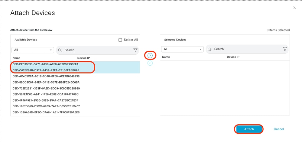
Wählen Sie zwei der C8000v-Geräte aus. Klicken Sie auf den nach rechts zeigenden Pfeil, und klicken Sie dann auf Anfügen.
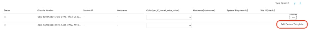
Klicken Sie auf den Geräten auf 3 Punkte (...), und navigieren Sie zu Gerätevorlage bearbeiten.
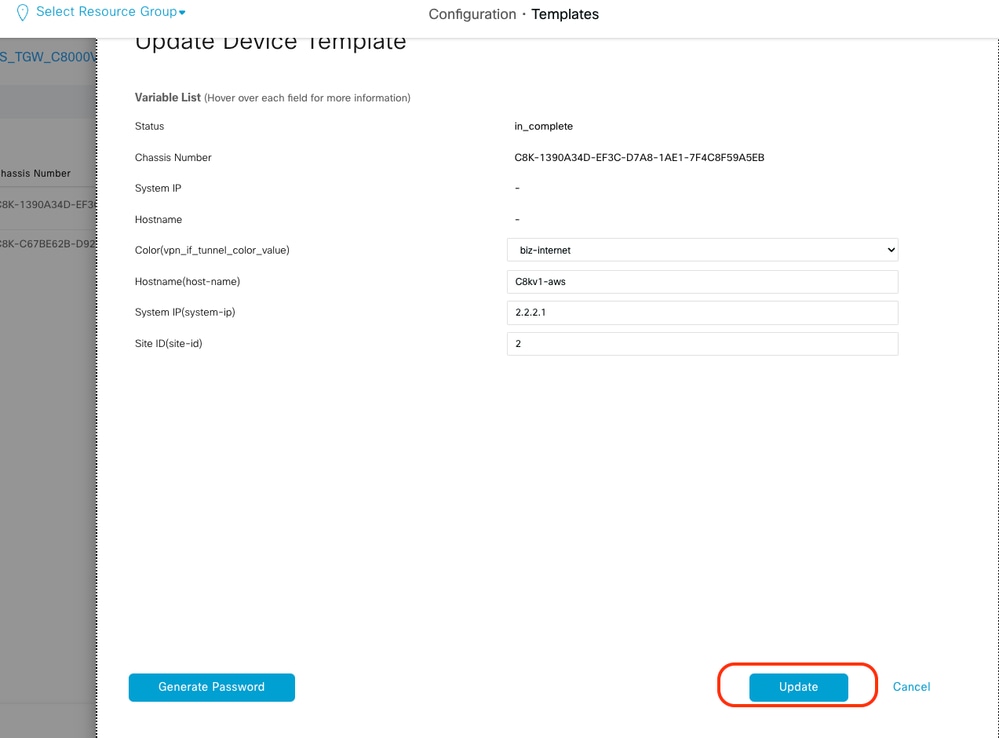
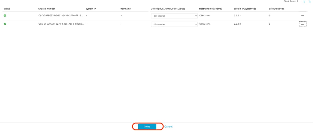
Klicken Sie auf das Dropdown-Menü, und wählen Sie Farbe, geben Sie Hostname, System-IP und Standort-ID ein. Klicken Sie nach Eingabe dieser Details auf Aktualisieren.
Geben Sie die Werte für die einzelnen Geräte ein, und klicken Sie dann auf Aktualisieren.
Beispiel:
On Device 1
Color: Select biz-internet from Dropdown
Hostname: C8kv1-aws
System IP: 10.2.2.1
Site: ID 2
On Device 2
Color: biz-internet Color: biz-internet
Hostname: C8kv2-aws
System IP: 10.2.2.2
Site: ID 2
Wenn Sie beide Geräte beendet haben, klicken Sie auf Weiter.
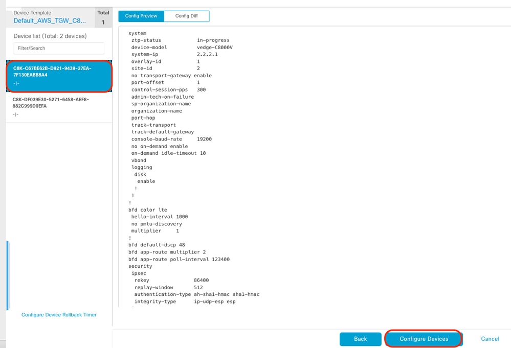
Klicken Sie auf eines der Geräte, und stellen Sie sicher, dass die Konfiguration korrekt ist. Klicken Sie auf Geräte konfigurieren.
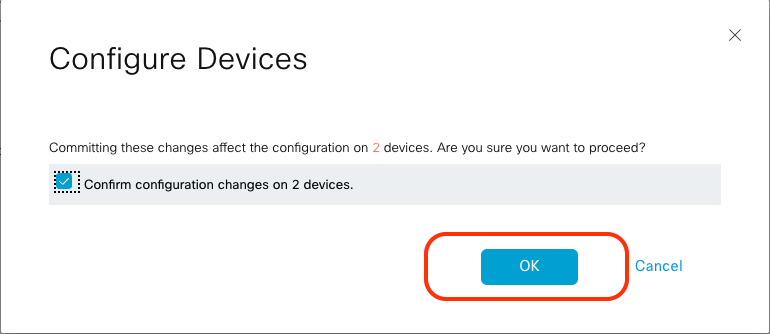
Aktivieren Sie im Popup-Fenster das Kontrollkästchen Konfigurationsänderungen auf zwei Geräten bestätigen, und klicken Sie dann auf OK.
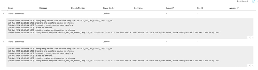
Bestätigen Sie, dass die Vorlagen für das Anschließen an die Geräte geplant wurden.
Schritt 2: Konfiguration der SD-WAN-Integration in AWS
Sie können Cloud onRamp für Umgebungen mit mehreren Clouds über den Cisco Catalyst SD-WAN Manager konfigurieren und verwalten.
Ein Konfigurationsassistent im Cisco Catalyst SD-WAN Manager automatisiert das Hochfahren des Transit-Gateways zu Ihrem Public Cloud-Konto und die Verbindungen zwischen Public Cloud-Anwendungen und den Benutzern dieser Anwendungen in Zweigstellen im Overlay-Netzwerk. Diese Funktion ist mit AWS Virtual Private Clouds (VPCs) auf Cisco Cloud-Routern kompatibel.
Ein Transit-Gateway ist ein Netzwerk-Transit-Hub, über den Sie Ihre VPC und Ihre lokalen Netzwerke miteinander verbinden können. Sie können eine vPC- oder eine VPN-Verbindung mit einem Transit-Gateway verbinden. Er fungiert als virtueller Router für den Datenverkehr, der zwischen Ihren VPC- und VPN-Verbindungen übertragen wird.
Cloud OnRamp für Multicloud unterstützt die Integration mit mehreren AWS-Konten.
AWS Cloud-Konto erstellen
Navigieren Sie zu Configuration > Cloud onRamp for Multicloud.
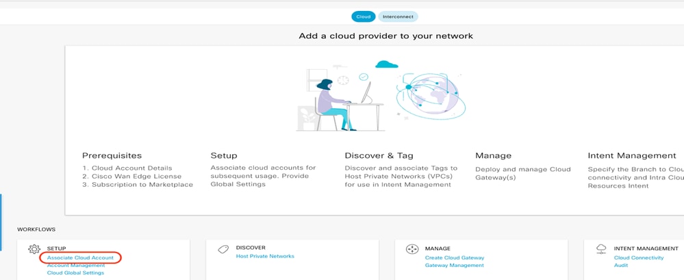
Klicken Sie unter Workflows > Setup auf Associate Cloud Account.
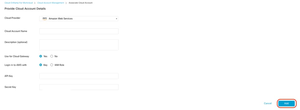
- Wählen Sie im Feld "Cloud Provider" in der Dropdown-Liste die Option Amazon Web Services aus.
- Geben Sie den Kontonamen in das Feld Cloud-Kontoname ein.
- Wählen Sie Ja aus, um Cloud Gateway zu erstellen.
- Wählen Sie das Authentifizierungsmodell aus, das Sie im Feld Bei AWS anmelden mit verwenden möchten.
- Wichtigste
- IAM-Rolle
Wenn Sie das Schlüsselmodell auswählen, geben Sie API-Schlüssel und geheimen Schlüssel in den entsprechenden Feldern ein.
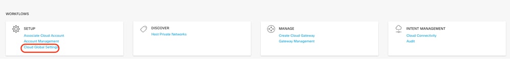
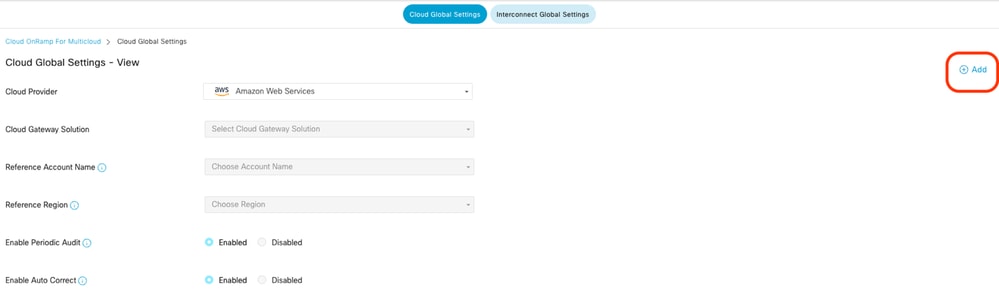
Globale Cloud-Einstellungen konfigurieren Klicken Sie auf Workflows > Setup > Cloud Global Settings.
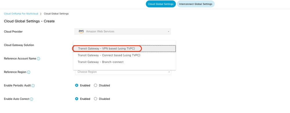
Klicken Sie auf Hinzufügen, klicken Sie auf das Dropdown-Menü für Cloud Gateway Solution, und wählen Sie dann Transit Gateway - VPN Base (über TVPC) aus.
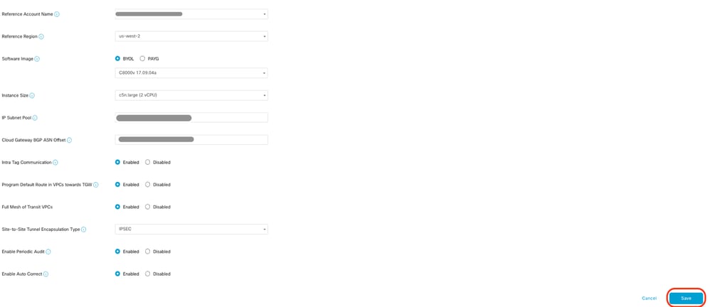
- Klicken Sie auf das Dropdown-Menü für Referenzkontoname, und wählen Sie das Konto aus.
- Klicken Sie auf das Dropdown-Menü für Referenzregion, und wählen Sie eine Region aus dem Dropdown-Menü aus.
-
Im Software-Imagefeld:
-
Klicken Sie auf BYOL, um ein eigenes Lizenz-Software-Image zu verwenden, oder auf PAYG, um ein nutzungsabhängiges Software-Image zu verwenden.
-
Wählen Sie aus der Dropdown-Liste ein Software-Image aus.
-
- Klicken Sie auf das Dropdown-Menü Instance Size (Instanzgröße), und wählen Sie dann die Größe C5n.large (2 CPU) für die Instanzen aus, die in Transit VPC ausgeführt werden.
- Geben Sie den IP-Subnetz-Pool x.x.x.x/24 ein.

Anmerkung: Sie können den Pool nicht ändern, wenn bereits einige Cloud-Gateways den Pool nutzen. Das Überlappen von Subnetzen ist nicht zulässig.
- Geben Sie den Cloud Gateway BGP ASN Offset 68520 ein.
Anmerkung: Der zulässige Startoffset-Bereich liegt zwischen 64520 und 65500. Er muss ein Vielfaches von 10 sein.
- Klicken Sie auf Site-to-Site Tunnel Encapsulation. Geben Sie das Dropdown-Menü ein, und wählen Sie dann IPSEC aus.
- Die übrigen Optionsfelder, die Sie als Standard beibehalten, sind aktiviert.
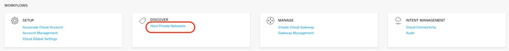
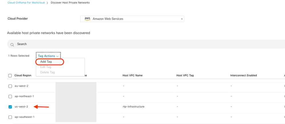
Als Nächstes müssen Sie Host-VPCs konfigurieren, indem Sie zum Haupt-Dashboard Cloud OnRamp For Multicloud zurückkehren und unter Erkennen auf Host Private Networks klicken.
- Wählen Sie die Host-VPCs oder VPCs aus, die an das Transit-Gateway angeschlossen werden sollen.
- Klicken Sie auf die Dropdown-Liste Region, um die vPCs basierend auf der jeweiligen Region auszuwählen.
- Klicken Sie auf Tag-Aktionen, um folgende Aktionen auszuführen:
Tag hinzufügen: Gruppieren Sie die ausgewählten vPCs, und markieren Sie sie.
Tag bearbeiten: Migration der ausgewählten vPCs von einem Tag zu einem anderen.
Tag löschen: Der Tag für die ausgewählten VPCs wird entfernt.
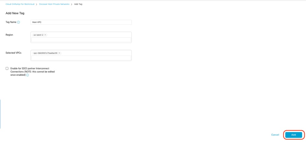
Mehrere Host-VPCs können unter einem Tag gruppiert werden. Alle vPCs mit demselben Tag gelten als eine Einheit. Ein Tag stellt die Verbindung sicher und ist für die Anzeige der vPCs inAbsichtsmanagement.
Geben Sie einen Tag-Namen ein (der Tag-Name kann beliebig sein), und klicken Sie dann auf Hinzufügen.
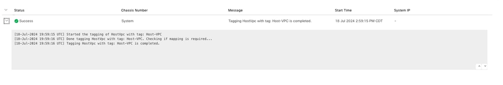
VPC-Tagging erfolgreich abgeschlossen.
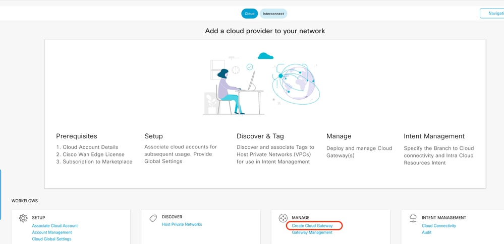
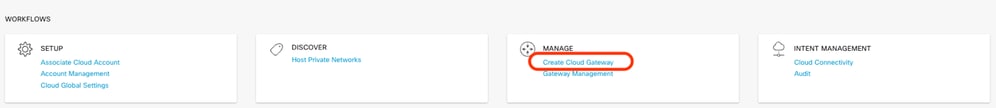
Kehren Sie zu Cloud onRamp for Multicloud zurück, und klicken Sie unter MANAGE auf Create Cloud Gateway (Cloud-Gateway erstellen).
- Klicken Sie auf das Dropdown-Menü für Cloud Provider, und wählen Sie AWS aus.
- Geben Sie einen Namen für das Cloud-Gateway ein.
- Klicken Sie auf das Dropdown-Menü Kontoname. Es enthält die zuvor eingegebenen Konteninformationen.
- Klicken Sie auf das Dropdown-Menü Region, und wählen Sie die Region aus, in der die Host-VPCs markiert wurden.
- Software-Image, Instanzgröße und IP-Subnetz-Pool werden automatisch aus dem zuvor gefüllten Global Cloud Gateway übernommen.
- Klicken Sie auf das Dropdown-Menü UUID (UUID). Es werden die beiden UUIDs für den C8000v angezeigt, die zuvor mit der Gerätevorlage verknüpft waren. Wählen Sie sie aus, und klicken Sie dann auf Hinzufügen.
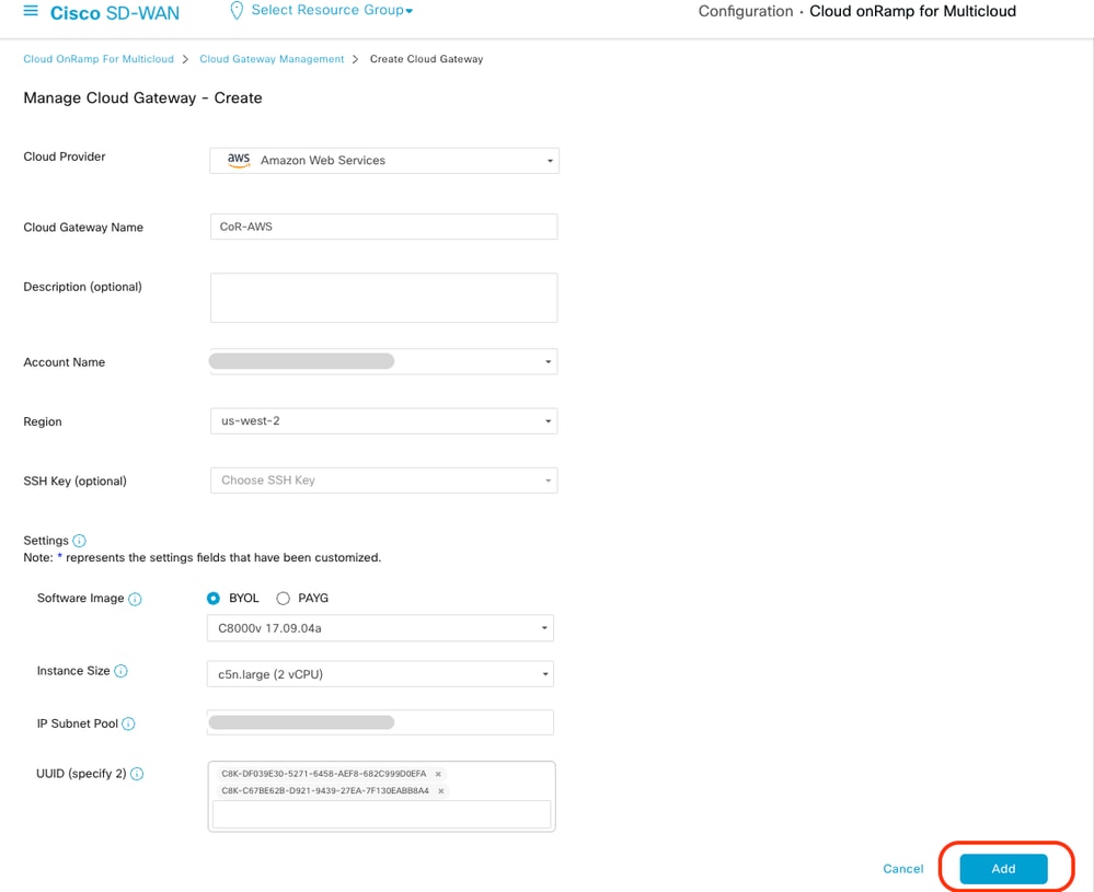
Nun beginnen die Cloud-Gateways mit der Erstellung und warten, bis die Bereitstellung des Cloud Gateway erfolgreich abgeschlossen wurde.
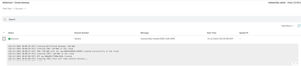
Anmerkung: WAN-Edges sind nach Abschluss des Vorgangs in wenigen Minuten erreichbar.
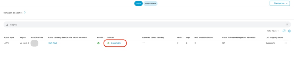
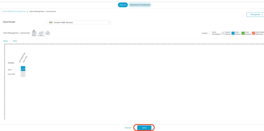
Zwei in AWS bereitgestellte C8000v-Geräte sind erreichbar. Klicken Sie nun auf Cloud Connectivity.
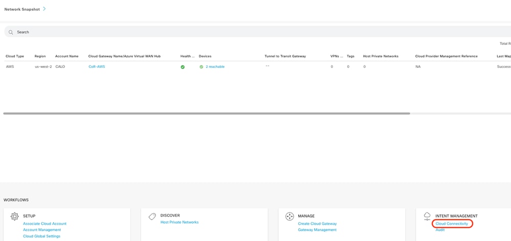
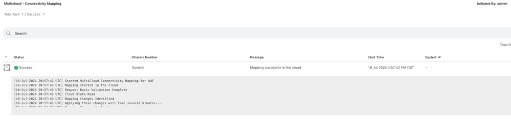
Klicken Sie auf Bearbeiten, um die VPN-Zuordnung durchzuführen, und wählen Sie VPN 1 aus, und klicken Sie dann auf Speichern.
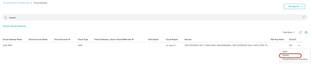
Schritt 3: So entfernen Sie Cloud Gateway
Um das Cloud Gateway zu löschen, wählen Sie unter Verwalten die Option Gateway Management aus.
Klicken Sie dann auf die 3 Punkte (...) auf dem gewünschten Cloud-Gateway und klicken Sie auf Löschen.
Überprüfung
In diesem Abschnitt werden die Ergebnisse für Überprüfungszwecke beschrieben.
Überprüfen Sie nach der Zuordnung, ob das VPN 1-Service-VPN (VRF) auf beiden C8000v in AWS vorhanden ist.
C8kv1-aws#show ip vrf
  Name                             Default RD            Interfaces
 1                                  1:1                   Tu100001
                                                           Tu100002
  65528                            <not set>               Lo65528
  65529                            <not set>               Lo65529
  Mgmt-intf                        1:512                      Gi1

C8kv2-aws#show ip vrf
  Name                             Default RD            Interfaces
  1                                  1:1                  Tu100001
                                                          Tu100002
  65528                            <not set>              Lo65528
  65529                            <not set>              Lo65529
  Mgmt-intf                        1:512                      Gi1
Außerdem werden die vom Router in der Zweigstelle vor Ort übernommenen OMP-Routen sowie die BGP-Routen von den Host-VPCs angezeigt.
C8kv1-aws#show ip route vrf 1
Routing Table: 1

Codes: L - local, C - connected, S - static, R - RIP, M - mobile, B - BGP
       D - EIGRP, EX - EIGRP external, O - OSPF, IA - OSPF inter area
       N1 - OSPF NSSA external type 1, N2 - OSPF NSSA external type 2
       E1 - OSPF external type 1, E2 - OSPF external type 2, m - OMP
       n - NAT, Ni - NAT inside, No - NAT outside, Nd - NAT DIA
       i - IS-IS, su - IS-IS summary, L1 - IS-IS level-1, L2 - IS-IS level-2
       ia - IS-IS inter area, * - candidate default, U - per-user static route
       H - NHRP, G - NHRP registered, g - NHRP registration summary
       o - ODR, P - periodic downloaded static route, l - LISP
       a - application route
       + - replicated route, % - next hop override, p - overrides from PfR
       & - replicated local route overrides by connected

Gateway of last resort is not set

      10.0.0.0/8 is variably subnetted, 4 subnets, 2 masks
m        10.1.50.64/26 [251/0] via 10.1.1.231, 02:55:52, Sdwan-system-intf
B        10.2.0.0/16 [20/100] via 169.254.0.17, 02:55:22
                     [20/100] via 169.254.0.13, 02:55:22
m        10.2.112.192/26 [251/0] via 10.1.1.221, 02:55:52, Sdwan-system-intf
m        10.2.193.0/26 [251/0] via 10.1.1.101, 02:55:52, Sdwan-system-intf
      169.254.0.0/16 is variably subnetted, 4 subnets, 2 masks
C        169.254.0.12/30 is directly connected, Tunnel100001
L        169.254.0.14/32 is directly connected, Tunnel100001
C        169.254.0.16/30 is directly connected, Tunnel100002
L        169.254.0.18/32 is directly connected, Tunnel100002
B     172.31.0.0/16 [20/100] via 169.254.0.17, 02:55:22
                    [20/100] via 169.254.0.13, 02:55:22

C8kv2-aws#show ip route vrf 1
Routing Table: 1
Codes: L - local, C - connected, S - static, R - RIP, M - mobile, B - BGP
       D - EIGRP, EX - EIGRP external, O - OSPF, IA - OSPF inter area
       N1 - OSPF NSSA external type 1, N2 - OSPF NSSA external type 2
       E1 - OSPF external type 1, E2 - OSPF external type 2, m - OMP
       n - NAT, Ni - NAT inside, No - NAT outside, Nd - NAT DIA
       i - IS-IS, su - IS-IS summary, L1 - IS-IS level-1, L2 - IS-IS level-2
       ia - IS-IS inter area, * - candidate default, U - per-user static route
       H - NHRP, G - NHRP registered, g - NHRP registration summary
       o - ODR, P - periodic downloaded static route, l - LISP
       a - application route
       + - replicated route, % - next hop override, p - overrides from PfR
       & - replicated local route overrides by connected

Gateway of last resort is not set
      10.0.0.0/8 is variably subnetted, 4 subnets, 2 masks
m        10.1.50.64/26 [251/0] via 10.1.1.231, 02:57:17, Sdwan-system-intf
B        10.2.0.0/16 [20/100] via 169.254.0.9, 02:57:08
                    [20/100] via 169.254.0.5, 02:57:08
m        10.2.112.192/26 [251/0] via 10.1.1.221, 02:57:17, Sdwan-system-intf
m        10.2.193.0/26 [251/0] via 10.1.1.101, 02:57:17, Sdwan-system-intf
      169.254.0.0/16 is variably subnetted, 4 subnets, 2 masks
C        169.254.0.4/30 is directly connected, Tunnel100001
L        169.254.0.6/32 is directly connected, Tunnel100001
C        169.254.0.8/30 is directly connected, Tunnel100002
L        169.254.0.10/32 is directly connected, Tunnel100002
B     172.31.0.0/16 [20/100] via 169.254.0.9, 02:57:08
                    [20/100] via 169.254.0.5, 02:57:08
Zugehörige Informationen
Revisionsverlauf
| Überarbeitung | Veröffentlichungsdatum | Kommentare |
|---|---|---|
1.0 |
07-Aug-2024 |
Erstveröffentlichung |
Beiträge von Cisco Ingenieuren
- Karthik Reddy YasaTechnical Consulting Engineer
 Feedback
Cisco kontaktieren
- Eine Supportanfrage öffnen

- (Erfordert einen Cisco Servicevertrag)