Cisco UCS for Google Cloud’s Anthos White Paper
Available Languages
Bias-Free Language
The documentation set for this product strives to use bias-free language. For the purposes of this documentation set, bias-free is defined as language that does not imply discrimination based on age, disability, gender, racial identity, ethnic identity, sexual orientation, socioeconomic status, and intersectionality. Exceptions may be present in the documentation due to language that is hardcoded in the user interfaces of the product software, language used based on RFP documentation, or language that is used by a referenced third-party product. Learn more about how Cisco is using Inclusive Language.
Google Cloud’s Anthos helps customers modernize their existing applications and build cloud-native applications anywhere to foster agility and cost savings. Though most cloud environments incorporate virtual machines as the building blocks for their infrastructure, they reduce flexibility to users by keeping them from directly accessing and making decisions about their hardware. Sharing CPU, memory, storage, and network resources can lead to unpredictable performance that can significantly impact large-scale or latency-sensitive workloads, such as financial transactions. This can prevent users from having full control of the appropriate hardware for their solution stack. Some workloads especially those that are sensitive to latency and need best performance are not suited to a virtualized environment. To free users from these disadvantages concerning hardware choices and prevent performance compromises, Google offers Google Cloud’s Anthos on bare metal. This solution combines the application platform benefits of Anthos with the hardware/software stack control, high performance, and cost effectiveness of a bare metal environment. By eliminating the costs and latency associated with the hypervisor layer, Anthos on bare metal lets users run their compute-intensive applications such as big-data analytics, machine learning, etc., efficiently. Users can therefore leverage the benefits of Google Cloud’s Anthos on bare metal with centralized management, increased flexibility, and developer agility and can choose hardware configurations and an operating system that best suits their workloads from a list of supported operating systems.
The Cisco Unified Computing System™ (Cisco UCS®) X-Series is a new, modular computing system, configured and managed from the cloud. It is designed to meet the needs of modern applications and improve operational efficiency, agility, and scale through an adaptable, future-ready, modular design. The system comprises modular components that can be assembled into systems through the Cisco Intersight™ cloud-operations platform. Cisco Intersight is a Software-as-a-Service (SaaS) infrastructure lifecycle management platform that delivers simplified configuration, deployment, maintenance, and support. Intersight brings the power of SaaS to deliver proactive monitoring, automation, and optimization of workloads across hybrid-cloud environments.
The Cisco UCS X210c Compute Node is the first computing device to integrate into the Cisco UCS X-Series Modular System. Up to eight compute nodes can reside in the 7-Rack-Unit (7RU) Cisco UCS X9508 Server Chassis, providing one of the highest densities of compute, I/O, and storage per rack unit in the industry. By bringing a high-performing storage tier closer to the compute node, it opens new deployment types by improving data-center efficiencies. System baseline performance testing is based on common I/O calibration tools such as Linux FIO, which can generate I/O patterns that mimic the type of I/O operations performed by typical enterprise databases. Therefore, The Cisco UCS X210c Compute Node is an ideal choice for running performance-critical applications.
Cisco UCS C240 Rack Servers are also well-suited for a wide range of storage and I/O-intensive applications such as big-data analytics, databases, collaboration, virtualization, consolidation, and high-performance computing in its two-socket, 2RU form factor. An increase in the number of CPU cores and higher memory capabilities from their previous generation have resulted in a 40 percent improvement in performance and efficiency.
This paper provides a variety of Reference Architectures (RAs) on Cisco UCS X- and C-Series servers for Google Cloud’s Anthos on bare metal. Both these series of servers are tailor-made for running performance-critical enterprise applications and databases. These servers are capable of adapting to the unpredictable needs of modern applications running enterprise workloads. Anthos on bare metal in combination with purpose-built Cisco UCS servers complement each other to aim at providing the best for user expectations.
Google Cloud’s Anthos on bare metal provides greater available CPU resources and optimizes cost for those looking for increased compute efficiency, low latency, and high throughput. Deployed on Cisco UCS server platforms powered by the latest Intel® Xeon® Scalable Processors, users can get the predictable performance that latency-sensitive data-center and edge workloads require.
Anthos on bare metal on Cisco UCS X-Series and C-Series servers allow users to operate with the full potential of their choice of UCS servers, storage, and networking combined with the on-demand flexibility that Google Cloud provides. Because users can exercise full control of their choice of hardware for the types of workloads they want to run, they get direct control of application performance with respect to application scale, security, and network latency.
In this paper we demonstrate the deployment of Anthos on bare metal with local persistent volumes for running stateful container applications. When the local disk of a server is attached directly to a single Kubernetes node, it is known as a local Persistent Volume (PV). This type of PV is preferred for compute-sensitive workloads that require best performance. However, the downside of this type of PV is that they are subjected to the availability of the underlying node and are not suitable for all applications. It is important to note that applications using local PVs must be able to tolerate this reduced availability and potential data loss; they also depend on the durability of the underlying disk. Therefore, this type of PV is only suited for enterprise applications that have built-in replication and that demand low network latency and high performance.
The refence architectures defined in this solution are tested on Cisco UCS X- and C-Series M6 platform servers; however, users can also deploy them on M7 platform servers. Cisco UCS X-Series compute nodes provide the functionalities of both blade and rack servers by offering compute density, storage capacity (up to six SAS/SATA/NVMe disk drives plus up to two M.2 drives), and expandability in a single system, embracing a wide range of data-center workloads. And the industry leading Cisco UCS C240 Rack servers are well suited for storage (up to 28 SAS/SATA/NVMe disk drives) and IO-intensive applications with its high-performance computing in two-socket. These UCS servers provide significant performance and efficiency gains that will improve users’ application performance. Both UCS X- and C-Series servers are tailor made to fit to the objectives with which Anthos bare metal was productized.
The audience for this paper includes system engineers, field consultants, IT administrators, technical architects, and anyone else interested in configuring and deploying Anthos on Cisco UCS platform servers. Readers are expected to have an understanding and working knowledge of containers, Kubernetes, Google Cloud, Google Kubernetes Engine (GKE), Linux, and Cisco UCS servers.
The scope of this document is restricted to demonstrating Google Cloud’s Anthos bare metal deployment on Cisco UCS M6 platform servers (Cisco UCS X-Series compute nodes and Cisco UCS C-Series rack servers) leveraging the local storage disks of the servers as local persistent volumes for application containers. As part of this demonstration, a variety of Reference Architectures (RAs) are illustrated to provide users an option to choose the right RA for their deployment model, considering High Availability (HA) not only at the Anthos cluster level but also at the level of the underlying hardware. This type of deployment model, with local disks of servers leveraged as persistent volumes should be considered only for the enterprise application that needs high performance and storage and has built-in data replication to mitigate any data loss due to node failure.
Note: Though Cisco UCS M7 platform servers can be leveraged for Anthos bare metal deployment, we have used M6 platform servers for testing and validating this solution.
Cisco UCS X-Series Modular System
The Cisco UCS X-Series Modular System begins with the Cisco UCS X9508 Server Chassis (Figure 1), engineered to be adaptable and future-ready. The X-Series is a standards-based open system designed to be deployed and automated quickly in a hybrid-cloud environment.
With a midplane-free design, I/O connectivity for the X9508 chassis is accomplished with front-loading vertically oriented computing nodes that intersect with horizontally oriented I/O connectivity modules in the rear of the chassis. A unified Ethernet fabric is supplied with the Cisco UCS 9108 Intelligent Fabric Modules (IFMs). In the future, Cisco UCS X-Fabric Technology interconnects will supply other industry-standard protocols as standards emerge. Users can easily update interconnections with new modules.
The Cisco UCS X-Series is powered by Cisco Intersight software, so it is simple to deploy and manage at scale.
The Cisco UCS X9508 Server Chassis (Figure 1) provides the following features and benefits:
● The 7RU chassis has 8 front-facing flexible slots. These slots can house a combination of computing nodes and a pool of future I/O resources, which may include Graphics Processing Unit (GPU) accelerators, disk storage, and nonvolatile memory.
● Two Cisco UCS 9108 IFMs at the top of the chassis connect the chassis to upstream Cisco UCS 6400 Series Fabric Interconnects (FIs). Each IFM offers these features:
◦ The module provides up to 100 Gbps of unified fabric connectivity per computing node.
◦ The module provides eight 25-Gbps Small Form-Factor Pluggable 28 (SFP28) uplink ports.
◦ The unified fabric carries management traffic to the Cisco Intersight cloud-operations platform, Fibre Channel over Ethernet (FCoE) traffic, and production Ethernet traffic to the fabric interconnects.
● At the bottom of the chassis are slots used to house Cisco UCS X9416 X-Fabric Modules, which enable GPU connectivity to the Cisco UCS X210c Compute Nodes.
● Six 2800-watt (W) Power Supply Units (PSUs) provide 54 volts (V) of power to the chassis with N, N+1, and N+N redundancy. A higher voltage allows efficient power delivery with less copper wiring needed and reduced power loss.
● Efficient, 4 x 100-mm, dual counter-rotating fans deliver industry-leading airflow and power efficiency. Optimized thermal algorithms enable different cooling modes to best support the network environment. Cooling is modular, so future enhancements can potentially handle open- or closed-loop liquid cooling to support even higher-power processors.
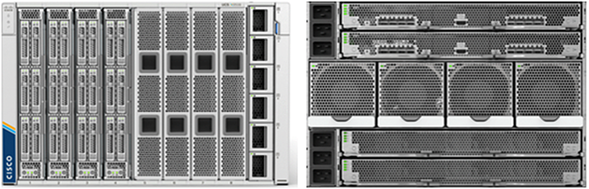
Cisco UCS X9508 Server Chassis, front (left) and back (right)
Since Cisco first delivered the Cisco Unified Computing System in 2009, our goal has been to simplify the data center. We pulled management out of servers and into the network. We simplified multiple networks into a single unified fabric. And we eliminated network layers in favor of a flat topology wrapped into a single unified system. With the Cisco UCS X-Series Modular System, the simplicity is extended even further:
● Simplify with cloud-operated infrastructure. We move management from the network into the cloud so that users can respond at the speed and scale of their business and manage all their infrastructure.
● Users can manage Cisco UCS X-Series Modular System resources to workload requirements with the Cisco Intersight cloud-operations platform. They can integrate third-party devices, including storage from NetApp, Pure Storage, and Hitachi. In addition, can gain intelligent visualization, optimization, and orchestration for all the applications and infrastructure.
◦ Simplify with an adaptable system designed for modern applications. Today’s cloud-native, hybrid applications are inherently unpredictable. They are deployed and redeployed as part of an iterative DevOps practice. Requirements change often, and users need a system that doesn’t lock them into one set of resources when they realize they need a different set. For hybrid applications, and for a range of traditional data-center applications, users can consolidate their resources on a single platform that combines the density and efficiency of blade servers with the expandability of rack servers. The result is better performance, automation, and efficiency.
◦ Simplify with a system engineered for the future. Embrace emerging technology and reduce risk with a modular system designed to support future generations of processors, storage, nonvolatile memory, accelerators, and interconnects. Gone is the need to purchase, configure, maintain, power, and cool discrete management modules and servers. Cloud-based management is kept up to date automatically with a constant stream of new capabilities delivered by the Cisco Intersight software-as-a-service (SaaS) model.
◦ Support a broader range of workloads. A single server type supporting a broader range of workloads means fewer different products to support, reduced training costs, and increased flexibility.
The Cisco UCS X-Series Modular System simplifies users’ data center, adapting to the unpredictable needs of modern applications while also accommodating traditional scale-out and enterprise workloads. It reduces the number of server types that users need to maintain, helping to improve operational efficiency and agility by reducing complexity. Powered by the Cisco Intersight cloud-operations platform, it shifts users’ focus from administrative details to business outcomes with hybrid-cloud infrastructure that is assembled from the cloud, shaped to their workloads, and continuously optimized.
The Cisco UCS X210c M6 Compute Node is the first computing device integrated into the Cisco UCS X- Series Modular System (Figure 2). Up to 8 computing nodes can reside in the 7RU Cisco UCS X9508 Server Chassis, offering one of the highest densities of computing, I/O, and storage resources per rack unit in the industry. The Cisco UCS X210c harnesses the power of the latest third-generation Intel Xeon Scalable Processors (Ice Lake). It includes the following features:
● CPU: Install up to two 3rd-generation Intel Xeon Scalable Processors with up to 40 cores per processor and 1.5 MB of Level-3 cache per core.
● Memory: Install up to thirty-two 256-GB DDR4 3200-MHz Dual Inline Memory Modules (DIMMs) for up to 8 TB of main memory. Configuring up to sixteen 512-GB Intel Optane™ persistent-memory DIMMs can yield up to 12 TB of memory.
● Storage: Install up to six hot-pluggable SSDs or NVMe 2.5-inch drives with a choice of enterprise-class RAID or pass-through controllers with four lanes each of PCIe Gen 4 connectivity and up to two M.2 SATA drives for flexible boot and local storage capabilities.
● Modular LAN-on-motherboard (mLOM) Virtual Interface Card (VIC): The Cisco UCS VIC 14425 occupies the mLOM slot on the server, enabling up to 50-Gbps unified fabric connectivity to each of the chassis IFMs for 100-Gbps connectivity per server.
● Mezzanine VIC (optional): The Cisco UCS VIC 14825 can occupy the mezzanine slot on the server at the bottom rear of the chassis. The I/O connectors of this card link to Cisco UCS X-Fabric Technology, which is planned for future I/O expansion. An included bridge card extends the two 50-Gbps network connections of this VIC through IFM connectors, bringing the total bandwidth to 100 Gbps per fabric (for a total of 200 Gbps per server).
● Security: The server supports an optional Trusted Platform Module (TPM). Additional features include a secure boot Field-Programmable Gateway (FPGA) and Anti-Counterfeit Technology 2 (ACT2) provisions.
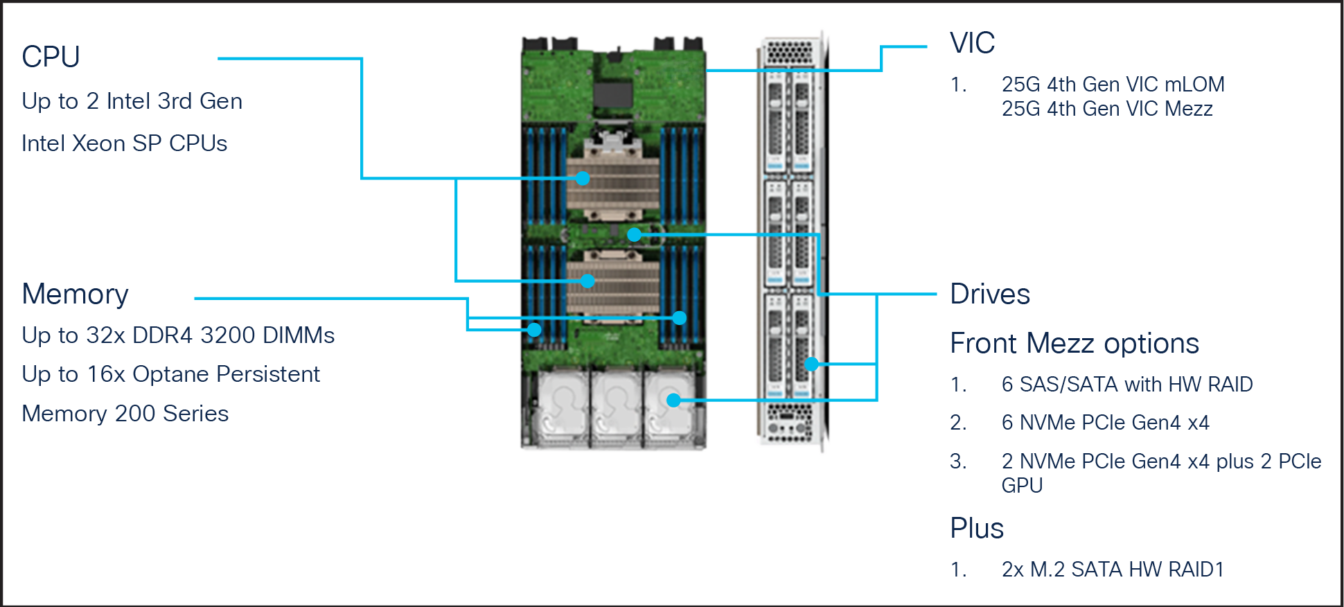
Front view of Cisco UCS X210c Compute Node
A specifications sheet for the Cisco UCS X210c M6 Compute Node is available at: https://www.cisco.com/c/dam/en/us/products/collateral/servers-unified-computing/ucs-x-series-modular-system/x210c-specsheet.pdf.
Cisco UCS 6400 Series Fabric Interconnect
Cisco UCS fabric interconnects provide a single point of connectivity and management for the entire Cisco UCS deployment (Figure 3). Typically deployed as an active-active pair, the fabric interconnects integrate all the components of a system into a single, highly available management domain that the Cisco UCS Manager or Cisco Intersight platform controls. Cisco UCS fabric interconnects provide a single unified fabric for the system, with low-latency, lossless, cut-through switching that supports LAN, Storage-Area Network (SAN), and management traffic using a single set of cables.
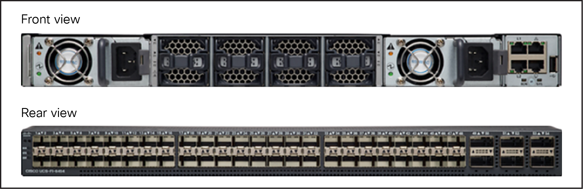
Cisco UCS 6400 Series Fabric Interconnect
The Cisco UCS 6454 Fabric Interconnect used in the current design is a 54-port fabric interconnect. This 1RU device includes 28 x 10-/25-Gbps Ethernet ports, 4 x 1-/10-/25-Gbps Ethernet ports, 6 x 40-/100-Gbps Ethernet uplink ports, and 16 unified ports that can support 10-/25-Gigabit Ethernet or 8-/16-/32-Gbps Fibre Channel, depending on the SFP design. Supports port-based licensing options with “pay-as-you-grow” model, allowing customers to add capacity as the networking needs of an individual system increase.
Note: To support the Cisco UCS X-Series, the fabric interconnects must be configured in Cisco Intersight Managed Mode (IMM). This option replaces the local management with Cisco Intersight cloud- or appliance-based management.
Cisco UCS 6536 Fabric Interconnect is a next-generation UCS fabric with 36 ports that supports Fibre Channel and Ethernet traffic concurrently in a unified fabric. With flexible blade/rack connectivity at 10/25/40/100-Gbps speed, which is incredibly faster than previous generations, it offers the reliability, efficiency, and scalability of Ethernet networks. It decreases TCO significantly by reducing the number of NICs, HBAs, switches, and cables required. Four unified ports support 40/100 GE or sixteen FC ports support 8/16/32-Gbps Fibre Channel. It also provides up to 7.42 Tbps throughput.
For more information on Cisco UCS 6536 Fabric Interconnects specifications, see: https://www.cisco.com/c/dam/en/us/products/collateral/servers-unified-computing/ucs-x-series-modular-system/cisco-ucs-6536-fabric-interconnect-spec-sheet.pdf.
Cisco UCS X210c M6 Compute Nodes support the following two Cisco fourth-generation VIC cards:
Cisco UCS VIC 14425 fits in to the mLOM slot in the Cisco X210c Compute Node and enables up to 50 Gbps of unified fabric connectivity to each of the chassis IFMs, for a total of 100 Gbps of connectivity per server. Cisco UCS VIC 14425 connectivity to the IFM and to the fabric interconnects is delivered through four 25-Gbps connections, which are configured automatically as two 50-Gbps port channels. The Cisco UCS VIC 14425 supports 256 virtual interfaces (both Fibre Channel and Ethernet) along with the latest networking innovations such as non-volatile memory express over fabrics (NVMeoF) over RDMA (ROCEv2), virtual extensible LAN (VXLAN), Network Virtualization Generic Routing Encapsulation (NVGRE) offload, and so on. Refer to Figure 4.
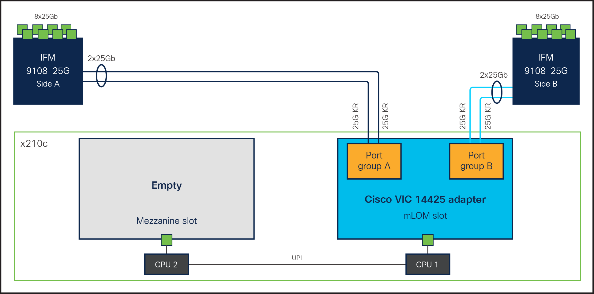
Single Cisco VIC 14225 in Cisco UCS X210c M6 Compute Node
For additional network bandwidth, the Cisco VIC 14825 can be used; it fits into the mezzanine slot on the server. A bridge card (UCSX-V4-BRIDGE) extends the 2x 50 Gbps of network connections of this VIC up to the mLOM slot and out through the IFM connectors of the mLOM, bringing the total bandwidth to 100 Gbps per fabric for a total bandwidth of 200 Gbps per server (Figure 5).
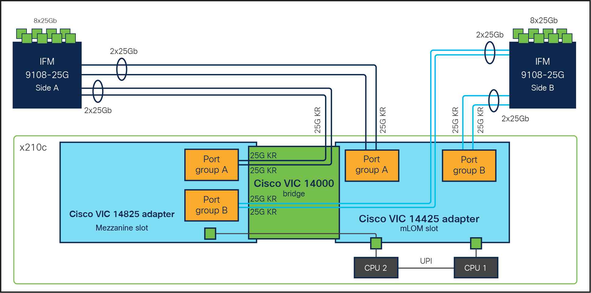
Cisco VIC 14425 and 14825 in Cisco UCS X210c M6 Compute Node
Note: In this solution we have used the Cisco UCS VIC 14425.
Cisco Intersight is a SaaS infrastructure lifecycle management platform that delivers simplified configuration, deployment, maintenance, and support (Figure 6). It is designed to be modular, so users can adopt services based on their individual requirements. It significantly simplifies IT operations by bridging applications with infrastructure, providing visibility and management from bare metal servers and hypervisors to serverless applications, thereby reducing costs and mitigating risks with embedded security. This unified SaaS platform uses a unified open application programming interface (API) design that natively integrates with third-party platforms and tools.
The Cisco Intersight API can help users to programmatically:
● Simplify the way they manage their infrastructure.
● Automate configurations and provision for their data center.
● Reduce provisioning time.
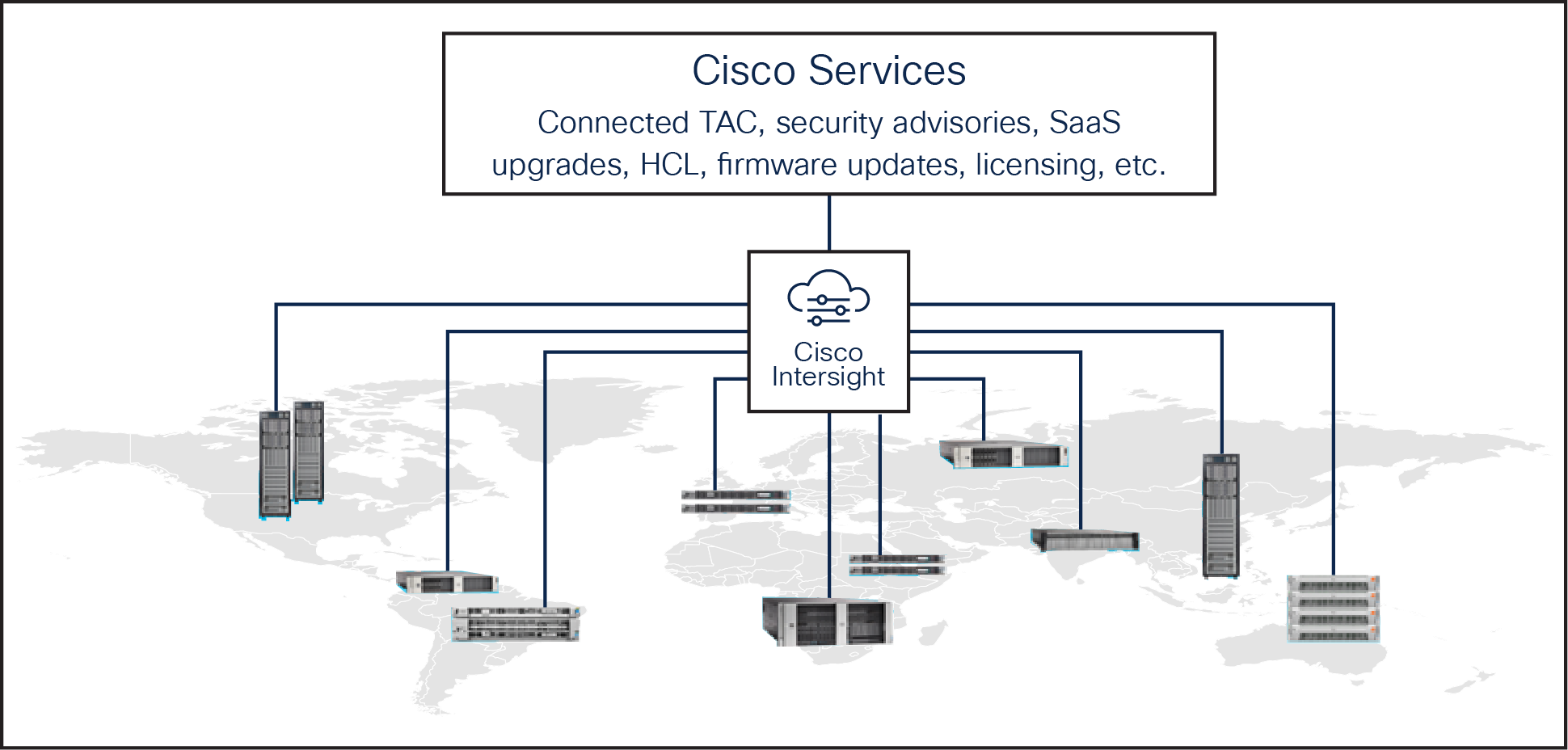
Cisco Intersight overview
The main benefits of Cisco Intersight infrastructure services follow:
● Simplify daily operations by automating many daily manual tasks.
● Combine the convenience of a SaaS platform with the capability to connect from anywhere and manage infrastructure through a browser or mobile app.
● Stay ahead of problems and accelerate trouble resolution through advanced support capabilities.
● Gain global visibility of infrastructure health and status along with advanced management and support capabilities.
● Upgrade to add workload optimization when needed.
Cisco Nexus 9000 Series Switches
The Cisco Nexus® 9000 Series Switches offer both modular and fixed 1/10/25/40/100 Gigabit Ethernet switch configurations with scalability up to 60 Tbps of nonblocking performance with less than five-microsecond latency, wire speed VXLAN gateway, bridging, and routing support. Cisco NX-OS is a purpose-built data-center operating system designed for performance, resiliency, scalability, manageability, and programmability at its foundation. It provides a robust and comprehensive feature set that meets the demanding requirements of virtualization and automation.
Google Cloud’s Anthos is a cloud-centric container platform to run modern applications anywhere consistently at scale. Anthos provides a single platform for the management of all Kubernetes workloads and operational consistency across hybrid and public clouds. It provides the ability to apply common configurations across infrastructures, while allowing users the flexibility to customize security policies and apply them to specific workloads and namespaces regardless of where the workloads are running. It uses an operator-based approach that can track cluster telemetry and log information from a single console.
Anthos enables users to manage GKE clusters and workloads running across environments. They can get a consistently managed Kubernetes experience with simple installs as well as upgrades validated by Google. Anthos can run on a user’s existing virtualized infrastructure and bare metal servers without a hypervisor layer. Anthos simplifies the application stack and reduces the costs associated with licensing a hypervisor.
There could be numerous reasons why organizations choose to deploy multiple clusters to achieve their technical and business objectives: for example, separating production from non-production environments, varying regulatory restrictions, or separating services across tiers, locales, or teams. However, using multiple clusters has its own difficulties and overheads in terms of consistent configuration, security, and management – for example, manually configuring one cluster at a time risks breakages, and it can be challenging to see exactly where errors are happening.
Anthos can help organizations by providing a consistent platform that allows them to:
● Modernize applications and infrastructure in place.
● Create a unified cloud-operating model (a single pane of glass) to create, update, and optimize container clusters wherever they are.
● Scale large multicluster applications as fleets – that is, logical groupings of similar environments – with consistent security, configuration, and service management.
● Enforce consistent governance and security from a unified control plane.
Figure 7 illustrates the basic Google Anthos architectural building blocks.
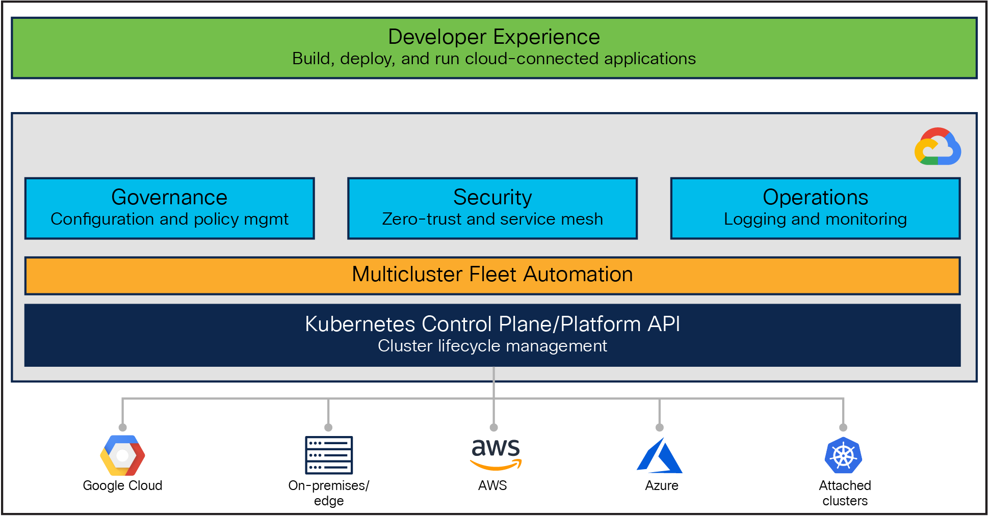
Google Anthos architecture
Anthos capabilities are built around the idea of the fleet: a logical grouping of Kubernetes clusters that can be managed together. A fleet can be entirely made up of GKE clusters on Google Cloud, or it can include clusters outside Google Cloud running on premises and on other public clouds such as AWS and Azure.
Anthos GKE is Google's managed Kubernetes implementation on Google Cloud, with a cloud-hosted control plane and clusters made up of compute-engine instances. While GKE on its own helps users automatically deploy, scale, and manage Kubernetes, grouping GKE clusters in a fleet lets them work more easily at scale, and allows them to use Anthos features in addition to the powerful cluster management features already offered by GKE.
Anthos clusters extend GKE for use with other infrastructure providers, including Azure, AWS, and on premises (either on VMware or bare metal). In these options, the Google-provided Kubernetes control plane runs in the user’s data center or cloud provider along with the user’s cluster nodes, with their clusters connected to the fleet-host project in Google Cloud.
Google Distributed Cloud Edge allows users to add on-premises GKE clusters to the fleet, this time running on Google-provided and maintained hardware and supporting a subset of Anthos features.
If GKE-based clusters are not the user’s only option, then Anthos also provides the ability to register conformant third-party Kubernetes clusters to the existing or created user’s fleet, such as EKS and AKS clusters, which are known as attached clusters. With this option, users can continue to run existing workloads where they currently are while adding value with a subset of Anthos features. Anthos does not manage the Kubernetes control plane or node components; it only manages the Anthos services that run on those clusters.
For all GKE-based clusters, including on-premises and public clouds, Anthos provides tools for cluster management and lifecycle management (create, update, delete, and upgrade), including command-line utilities and management from the Google Cloud Console.
For more information about Anthos deployment options, see: https://cloud.google.com/anthos/deployment-options.
This section provides details on the hardware components and software versions used in this solution.
Table 1. Hardware and software components used
| Component |
Model |
Software version |
| Management |
2x Cisco UCS 6454 Fabric Interconnects |
4.2 (1h) |
| Compute |
5x Cisco UCS X210c M6 Compute Nodes |
5.(4a) |
| 5x Cisco UCS C240 M6 Rack Servers |
4.2(2f) |
|
| Processor |
Intel Xeon 3rd-generation scalable processors
●
Silver 4309Y, 2.8 GHz for control plane nodes
●
Gold 6348, 2.60 GHz for user nodes
|
|
| Adapters |
Cisco UCS Virtual Interface Card (VIC) 14425 |
Driver: 7.716.2.0 |
| Storage |
● 4x 480 GB SATA SSD drives for LVP (Anthos local PV)
● 2x 240 GB M.2 Serial Advanced Technology Attachment (SATA) SSDs and associated RAID controllers for OS boot drive
|
|
| Cisco software |
Cisco Intersight software |
|
| Google Anthos |
Google Anthos GKE |
1.15 |
| Operating system |
Red Hat Enterprise Linux |
8.5 |
Reference architecture example for user and control plane (HA mode)
This section illustrates a variety of reference architectures for deploying Google’s Anthos on bare metal on the Cisco UCS suite of servers. For Anthos on bare metal, Cisco UCS X-Series compute nodes and C-Series servers are positioned based on their features and capabilities.
With Cisco UCS X-Series compute nodes deployed in a single chassis
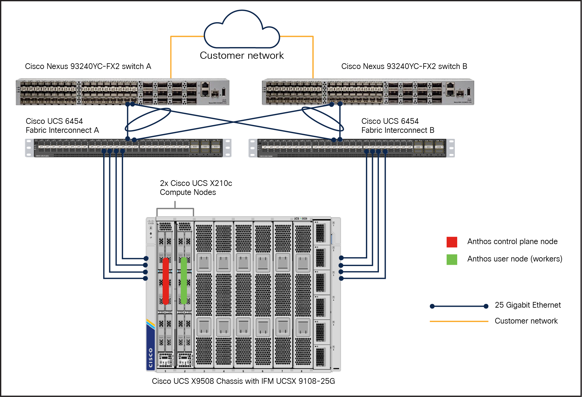
This is the reference architecture model used to test and validate Google Anthos bare metal clusters. In this model, an Anthos admin cluster is deployed with three control plane nodes for HA (3x Cisco UCS X210c nodes) on the Cisco UCS X9508 chassis. In the user cluster, there are two nodes to run workloads deployed on this bare metal cluster (2x Cisco UCS X210c nodes). The scale up and down of the user cluster node is tested and works seamlessly. This reference architecture (Figure 8) shows Anthos bare metal deployment in HA mode with respect to the admin cluster.
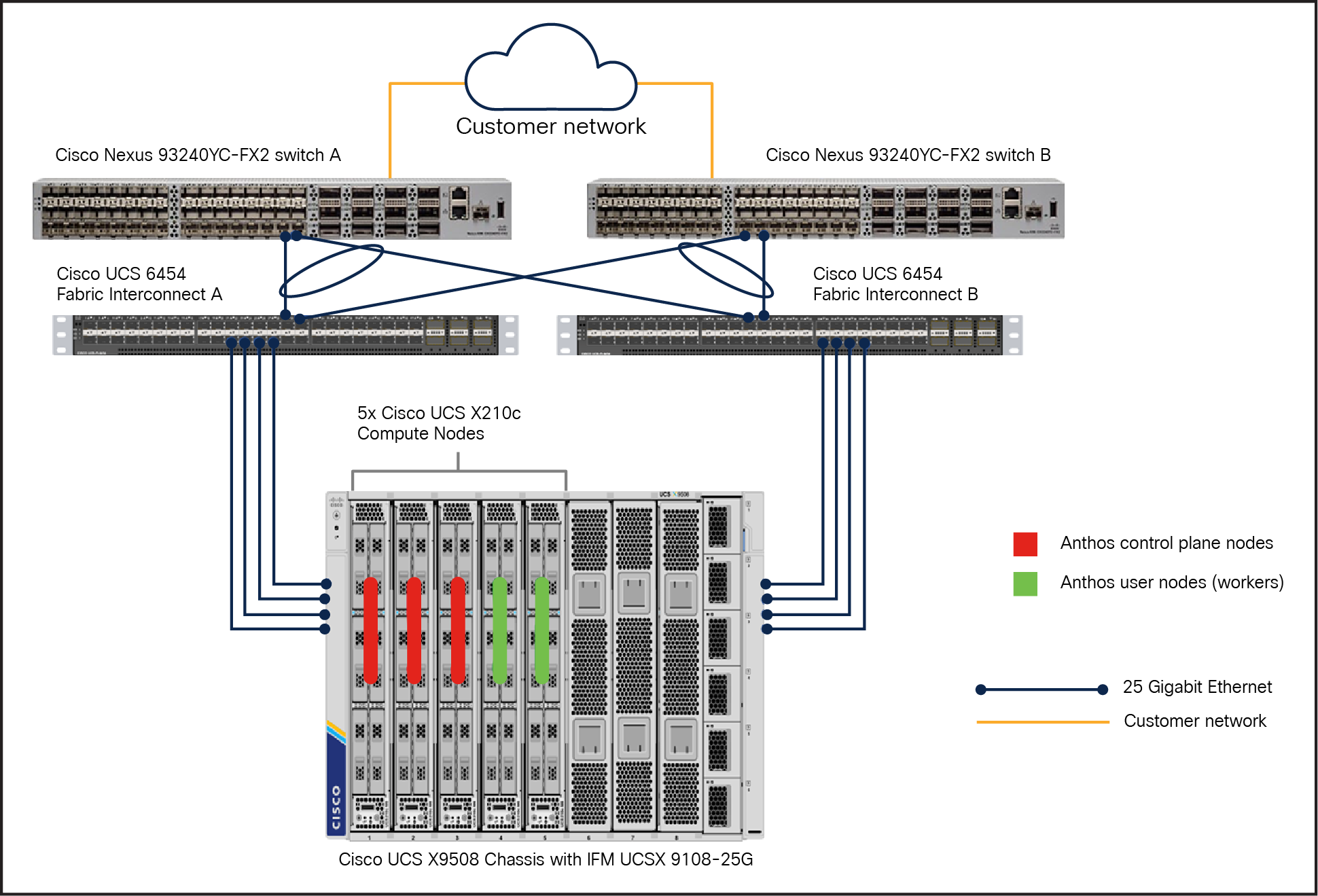
Reference architecture for Anthos bare metal in HA mode on Cisco UCS X-Series compute nodes
The Cisco UCS X9508 Chassis allows use of two I/O modules for redundancy or aggregation of bandwidth. With redundant hot-swappable power supplies and fans, it provides high serviceability, uninterrupted service during maintenance, and high availability in multiple configurations. The Cisco UCS X9508 Chassis is fully redundant and highly resilient. It also provides extensive environmental monitoring and allows the use of user thresholds to optimize environmental management of the chassis. Chassis failure is rare; however, to mitigate the effect of a single chassis failure, we have another reference architecture, which is explained in the following section.
With Cisco UCS X-Series compute nodes deployed across two chassis
In this model, the Anthos admin cluster, with two control plane nodes (2x Cisco UCS X210c nodes) and one user node for running workloads, is deployed on one Cisco UCS X9508 Chassis, and one control plane node (1x Cisco UCS X210c Computer Node) and two user nodes for running workloads are deployed on another X9508 chassis (Figure 9).
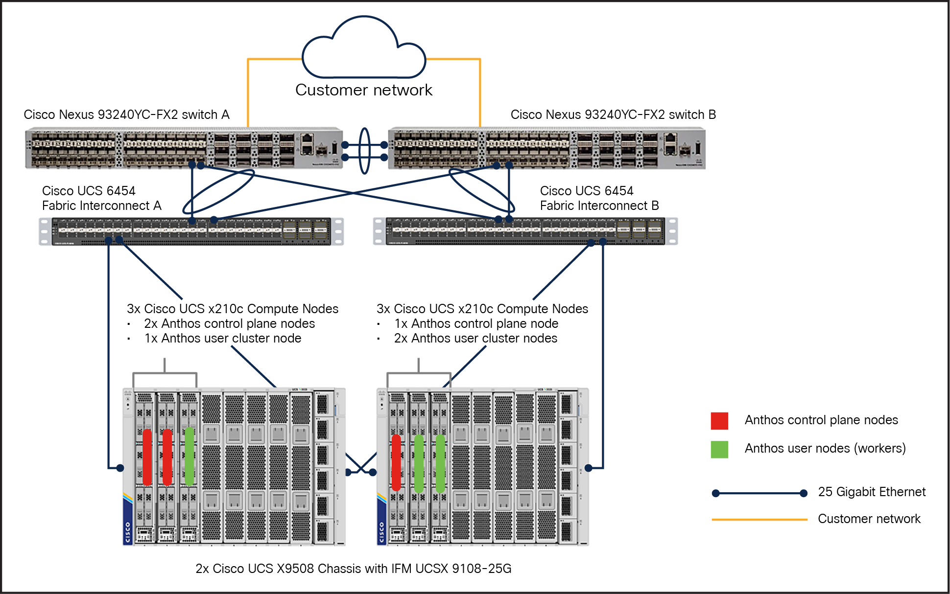
Reference architecture for Anthos bare metal in HA mode on Cisco UCS X-Series compute nodes with two chassis
This reference architecture not only caters for the Anthos cluster-based HA, but also provides fault tolerance at the chassis level.
With Cisco UCS C-Series rack servers
In this model, an Anthos admin cluster with three control plane nodes (3x Cisco UCS C240M6 Rack Servers) incorporates two user nodes in the user cluster for running workloads. This RA leverages Cisco UCS C240M6 Rack Servers for deploying Anthos on bare metal clusters.
When Cisco UCS servers are attached to Cisco UCS fabric interconnects, they become part of a single, highly available management domain. Cisco UCS Manager software on these fabric interconnects provides the ability to programmatically control server, network, and storage resources with a unified, policy-driven management so they can be efficiently managed at scale.
However, Cisco does support direct connectivity, wherein Cisco UCS servers are connected to a pair of upstream switches directly without UCS fabric interconnects, while centralized management lies with Cisco Intersight™. Cisco Intersight, a SaaS-based cloud-operations platform works in conjunction with Cisco Integrated Management Controller (IMC), in which users can simply associate a model-based configuration to provision servers, associated storage, and fabric automatically, regardless of the form factor. Using profiles, users can consistently align policy, server personality, and workloads anywhere at any time. These policies can be created once and used to simplify server deployments, resulting in improved productivity and compliance and lower risk of failures due to inconsistent configuration.
In this Reference Architecture (RA) (Figure 10), Cisco UCS C-Series servers are connected directly to the upstream switches. This RA also provides fault tolerance so users have the flexibility to scale up and down the Anthos cluster nodes in the rack. In this RA, both the Anthos admin cluster and user cluster are deployed in HA mode with three nodes in each cluster (Figure 10).
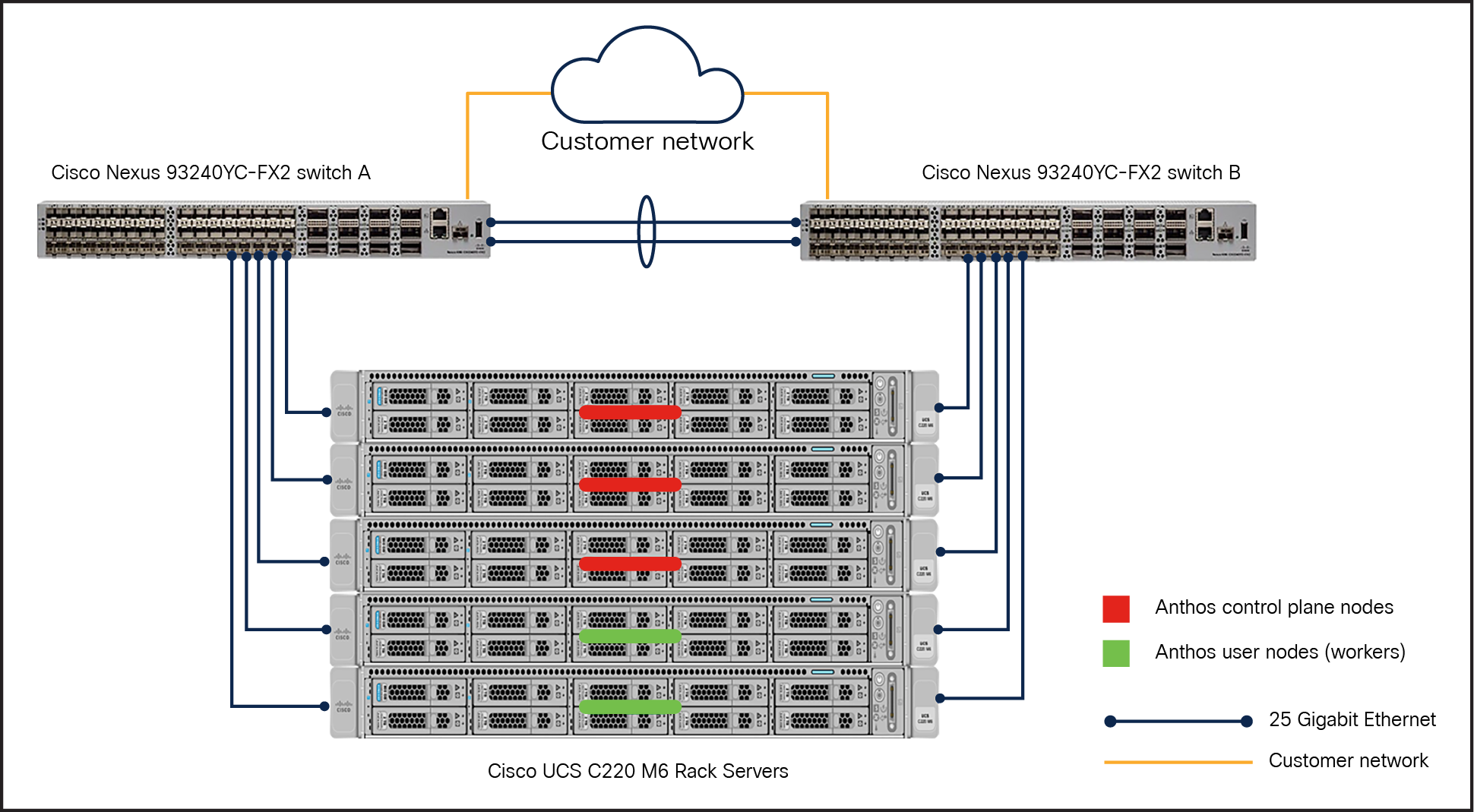
Reference architecture for Anthos bare metal in HA mode on Cisco UCS C240M6 Rack Servers
With a mix of Cisco UCS X-Series compute nodes and C-Series rack servers
In this model, an Anthos admin cluster with three control plane nodes (3x Cisco UCS C240M6 Rack Servers) and a user node is deployed on C-Series M6 servers. While one or two user nodes are deployed on the X-Series (2x Cisco UCS X210c Computer Nodes). Note that both the user nodes are part of one single user cluster. Anthos supports heterogeneous nodes that can be added to the user cluster to scale up the nodes as needed for running workloads. This reference architecture (Figure 11) is fault tolerant because no cluster nodes are completely bound to either Cisco UCS C- or X-Series. This RA also illustrates HA mode of deployment for both admin and user clusters, with three nodes in each cluster.
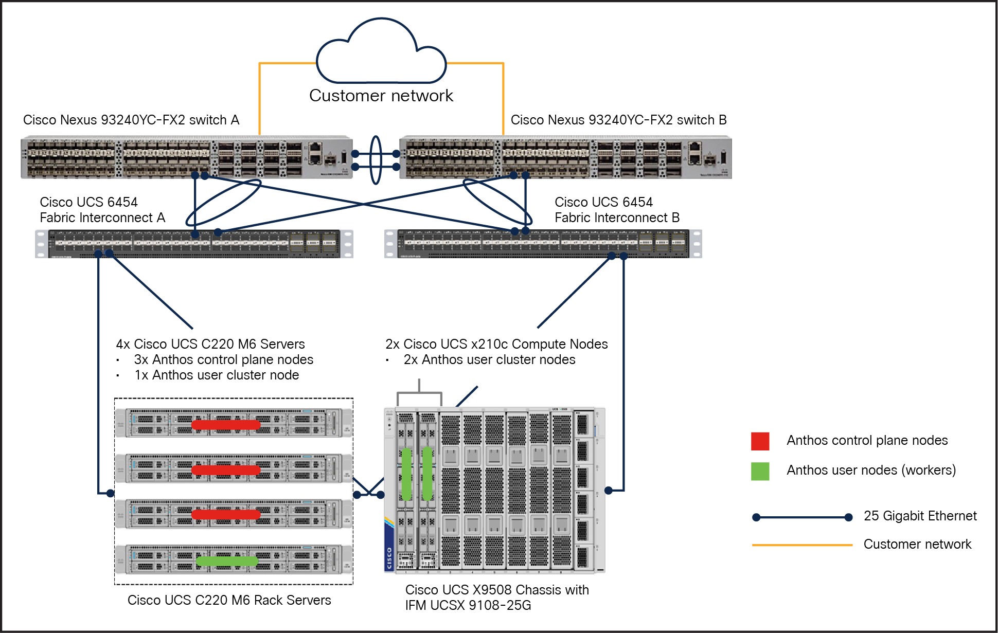
Reference architecture for Anthos bare metal in HA mode on both Cisco X-Series and C-Series M6 servers
Reference architecture example for user and control plane (non-HA mode)
In this section, reference architecture without HA at the Anthos cluster level is shown. These RAs are supported by Anthos and valid for certain deployments including those at the edge. In this section we have shown the two RAs built on Cisco UCS C-Series M6 Rack Servers and Cisco UCS X210c M6 Compute Nodes. In both these RAs, there are two nodes, one each for the admin and the user cluster, as shown in the following figures 12 and 13.
Similarly, users can deploy both admin cluster nodes and user cluster nodes in a single cluster that serves as both a user cluster and as an admin cluster. This type of deployment is referred to as a standalone cluster deployment and does not need a separate admin cluster. It is advantageous when a user wants to manage every single cluster independently, run a single workload type, or run in edge locations. It supports the edge profile, which significantly reduces system resource requirements, and is recommended for edge devices with high resource constraints.
Note: For running critical workloads, it is advisable to consider HA deployment even in a single cluster deployment model with a minimum of three nodes in the same single cluster with admin cluster residing in the user cluster.
With Cisco UCS C-Series rack servers
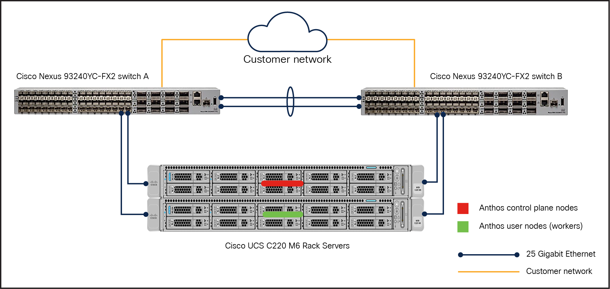
Reference architecture for Anthos bare metal in non-HA mode on Cisco UCS C240 M6 Rack Servers
With Cisco UCS X-Series compute nodes
Reference architecture for Anthos bare metal in non-HA mode on Cisco UCS X210c M6 Compute Nodes
Note: It is important to note that in all these deployment models we are using local PVs for container storage persistency. If a node goes down, the local PV (LVP node mount) of that node is lost. Therefore, applications using local PVs must be able to tolerate this reduced availability and potential data loss, and the durability characteristics of the underlying disk should be taken into consideration. It is recommended that enterprise-critical containerised applications that demand high performance and possess built-in replication and data protection and implement features such as snapshots and clones should be considered for Anthos bare metal with local PV.
Anthos clusters on bare metal supports the following deployment models:
● Admin and user cluster deployment
● Hybrid cluster deployment
● Standalone cluster deployment
Admin and user cluster deployment is used when a user has multiple clusters in the same data center that needs to be managed from a centralized place or has larger deployments that need isolation between different teams or between development and production workloads. We have used this deployment model for testing and validation in this solution. Figure 14 illustrates the admin and user cluster deployment model.
For more information on the types of deployment model, see: https://cloud.google.com/anthos/clusters/docs/bare-metal/latest/installing/install-prep
This deployment model consists of the following clusters:
● One admin cluster in HA: The central management point that provides an API to manage user clusters. The admin cluster only runs management components. A minimum of three control plane nodes in an admin cluster is required for HA.
● One or more user clusters: Contain the control plane nodes and the worker nodes, which run user workloads.
Note: We have a 3-node admin cluster and a 2-node user cluster deployed for this whitepaper effort.
This model meets the following requirements:
● Provides a centralized control plane and API to manage user clusters' lifecycles.
● Provides isolation between different teams.
● Provides isolation between development and production workloads.
● User’s do not have to share SSH credentials and service account keys with cluster owners.
● This model also allows users to integrate their deployment with their own control planes.
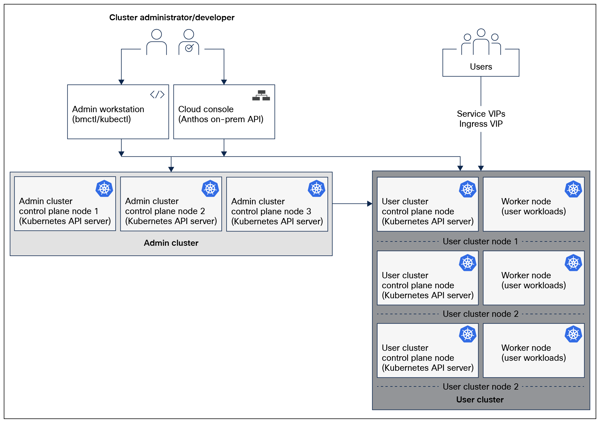
Google Anthos logical architecture for admin and user cluster deployment model in HA configuration
Ease of server fleet management in Cisco Intersight
Kubernetes fleet is a logical set of clusters that are managed as a single domain. A fleet can be a collection of all Kubernetes clusters managed across an organization or simply a set of clusters within an organization that needs similar management. Google Cloud supports fleet management, which enables users to manage, monitor, and govern a heterogeneous fleet of Kubernetes clusters and applications running on them.
Cisco Intersight provides adaptive cloud-powered infrastructure management with automation for agile IT delivery anywhere at any scale. It allows fleet management at the infrastructure level by enabling users to manage a fleet of Cisco UCS suite of servers by abstracting the management complexities by providing a single point of connectivity and management whether on-premises, edge, or private/hybrid/public clouds. Intersight allows users to consistently align policy and server personality and manage workloads. Server policies and profiles in Intersight, by managing server personas that are attached to fleet servers, simplify server deployments, improving productivity and compliance and lowering the risk of failures due to inconsistent configurations. Figure 15 illustrates fleet management of UCS servers in Cisco Intersight.
Some of the benefits of Cisco Intersight for managing a Cisco UCS server fleet:
● Unified monitoring and management: simplify the monitoring and management of Cisco® and third-party compute, network, storage, integrated systems, and virtualization all from one IT-operations platform
● Configuration, provisioning, and installation: policy-based profiles and templates for deployment and configuration enable users to consistently provision and operate their IT infrastructure and resources, maintain standardization, eliminate configuration errors, and minimize configuration drift for the server fleet. Leverage policies and templates or clone profiles to quickly provision where they are deployed.
● Hardware Compatibility List (HCL): evaluate and mitigate the impact of service issues from running non-validated combinations of firmware, server models, processors, adapters, operating systems, and driver versions. Use Cisco UCS tools as add-ons for VMware or use the OS-discovery tool (an open-source script) to collect OS and driver information to evaluate HCL compliance.
● Security: security advisories to alert users of potential risks with threat summaries, identify devices impacted, and provide recommended remediation. Provide audit logs, automatic notifications when a threat or vulnerability is detected, end-of-life notices, and device support status to help users keep their infrastructure updated.
● Automation and REST API: obtain RESTful APIs to manage IT infrastructure and resources across multiple data centers and edge locations. Supports the OpenAPI specification (OAS) to provide full programmability and deep integration. Python and PowerShell SDKs enable integrations with Ansible, Chef, Puppet, and other DevOps and IT operations management (ITOM) tools. Supports infrastructure-management operations across Cisco and third-party compute, network, storage, integrated systems, virtualization, containers, and other automation engines such as HashiCorp Terraform and Red Hat Ansible.
● Seamless integration and upgrades: upgrade firmware and software for Cisco UCS domains, UCS servers, and Cisco HyperFlex® clusters.
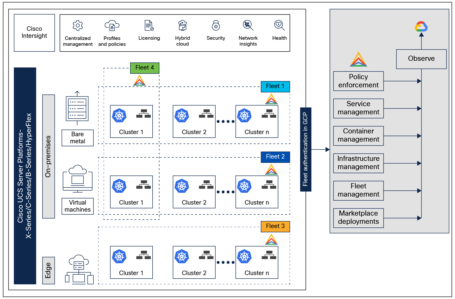
Fleet management at both Infrastructure and Kubernetes layers
In the figure, we can see that there are four types of fleets.
Fleet 1 represents a set of bare metal servers managed as a single fleet. In this fleet, any UCS platform servers (UCS X-Series/C-Series/B-Series servers) with any form factor are managed either due to a similar server persona based on the workloads it runs, or based on consistent policy enforcements, etc. As mentioned earlier, the fleet of servers can be on premises, at the edge, or in any cloud.
Fleet 2 represents a set of VMs managed as a single fleet. The VMs can either be running on Cisco HyperFlex Systems, custom VMware ESXi–based VMs, or a combination of both. Here, too, VMs are grouped into a fleet based on the type of workloads they run, or they can be organization-based, etc. A fleet is highly customizable, and Cisco Intersight can manage any server platform or VMs as a fleet with server profiles instantiated from a template having the same or similar configurations.
Similarly, Fleet 3 represents a server fleet that belongs to an edge deployment. However, a fleet can be a combination of all of these environments. Fleet 4 represent a heterogenous environment along with heterogenous suites of Cisco UCS servers.
Anthos and Google Cloud use the concept of a fleet to simplify managing multicluster deployments. A fleet provides a way to logically group and normalize Kubernetes clusters, making administration of infrastructure easier. A fleet can be made up entirely of Google Kubernetes Engine clusters on Google Cloud, or it can include clusters outside of Google Cloud. A growing number of Anthos and Google Cloud components use fleet concepts such as “same identity” or “same namespaces” to simplify working with multiple clusters. Adopting fleets helps users uplevel management from individual clusters to entire groups of clusters. Furthermore, the normalization that fleets require can help teams within an organization to adopt similar best practices to those used at Google.
For more information on how a fleet works on Google Cloud, see: https://cloud.google.com/anthos/fleet-management/docs/fleet-concepts.
Anthos GKE on-premises network topology
Users need to consider the following information to meet network requirements:
● The control plane nodes run the load balancers, and they all have Layer-2 connectivity, whereas other connections, including worker nodes, only require Layer-3 connectivity.
● Configuration files define IP addresses for worker-node pools. Configuration files also define VIPs for the following purposes:
◦ Services
◦ Ingress
◦ Control plane access through the Kubernetes API
● Connectivity to Google Cloud
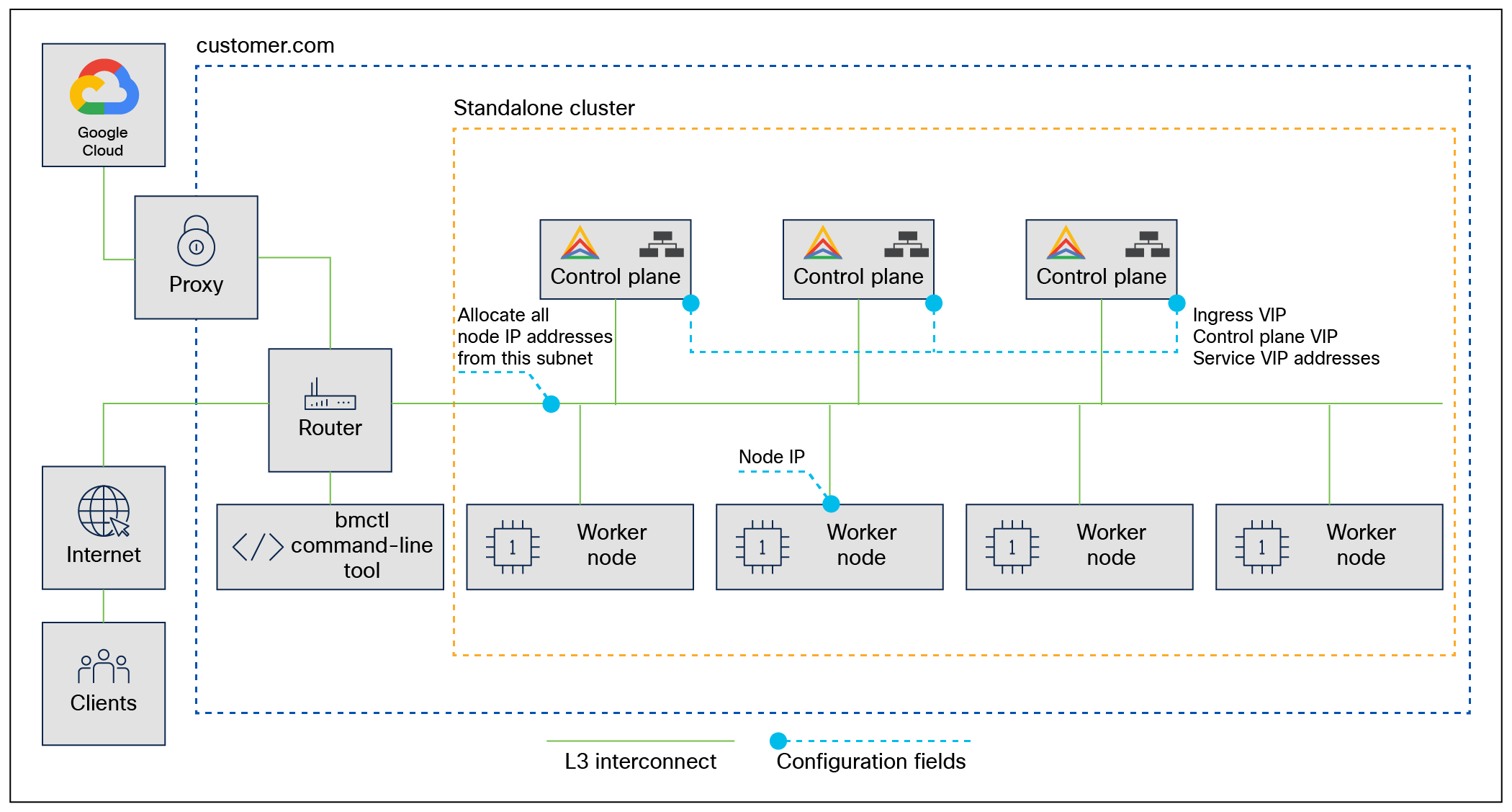
Google Anthos bare metal network topology
For more information on pod networking and port usages, see: https://cloud.google.com/anthos/clusters/docs/bare-metal/latest/concepts/network-reqs.
The Cisco UCS X9508 Server Chassis is equipped with the Cisco UCSX 9108-25G Intelligent Fabric Modules (IFMs). The Cisco UCS X9508 chassis connects to each Cisco UCS 6454 Fabric Interconnect using four 25GE ports, as shown in Figure 16. If customers require more bandwidth, all eight ports on the IFMs can be connected to each fabric interconnect.
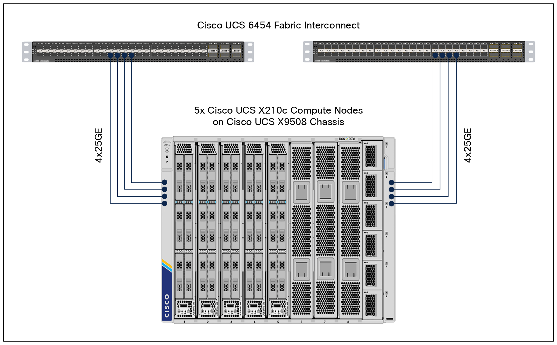
Cisco UCS X9508 Server Chassis connectivity to Cisco UCS fabric interconnects
Cisco Nexus Ethernet connectivity
The Cisco Nexus 9000 Series Switches device configuration covers the core networking requirements for Layer-2 and Layer-3 communication. Some of the key Cisco NX-OS features implemented within the design are:
● Feature interface-vans – Allows for VLAN IP interfaces to be configured within the switch as gateways.
● Feature HSRP – Allows for Hot Standby Routing Protocol configuration for high availability.
● Feature LACP – Allows for the utilization of Link Aggregation Control Protocol (802.3ad) by the port channels configured on the switch.
● Feature VPC – Virtual Port-Channel (vPC) presents the two Nexus switches as a single “logical” port channel to the connecting upstream or downstream device.
● Feature LLDP - Link Layer Discovery Protocol (LLDP), a vendor-neutral device discovery protocol, allows the discovery of both Cisco devices and devices from other sources.
● Feature NX-API – NX-API improves the accessibility of CLI by making it available outside of the switch by using HTTP/HTTPS. This feature helps with configuring the Cisco Nexus switch remotely using the automation framework.
● Feature UDLD: to enable unidirectional link detection for various interfaces.
Cisco UCS Fabric Interconnect 6454 Ethernet connectivity
Cisco UCS 6454 Fabric Interconnects (FIs) are connected to Cisco Nexus 9000 Series Switches using 25GE connections configured as virtual port-channels (vPCs). Each FI is connected to both Cisco Nexus switches using a 25G connection; additional links can easily be added to the port channel to increase bandwidth as needed. Figure 17 covers the physical connectivity details.
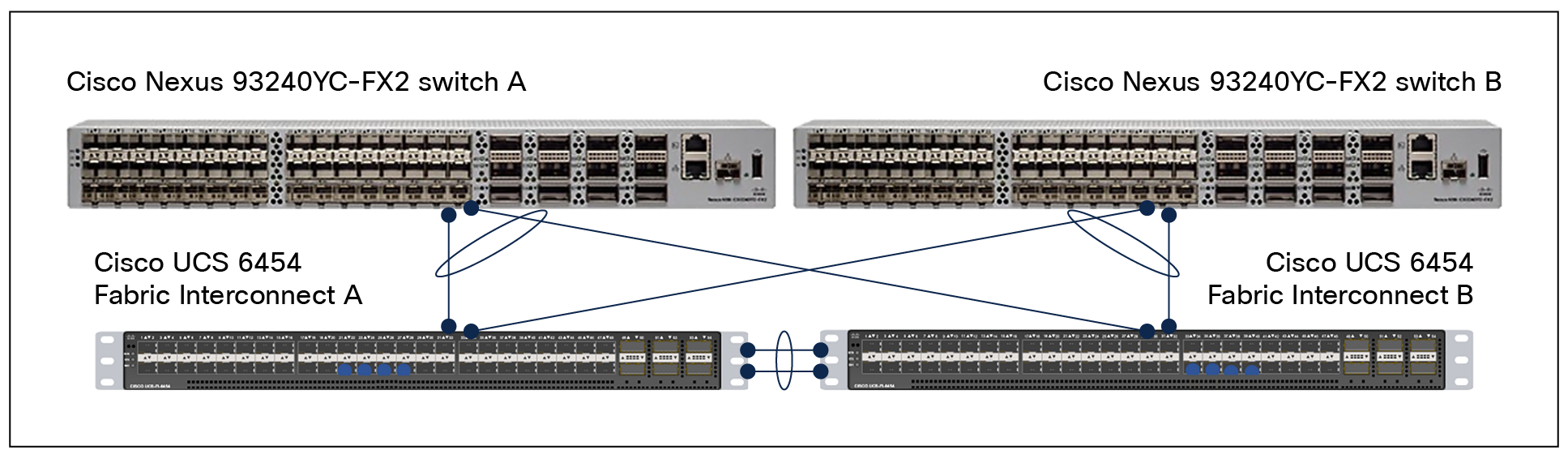
Connectivity of Cisco Nexus 9000 Series Switches with Cisco UCS 6454 Fabric Interconnects
Cisco UCS configuration – Cisco Intersight Managed Mode
Cisco Intersight Managed Mode standardizes policy and operation management for Cisco UCS servers. The compute nodes in Cisco UCS X-Series and C-Series servers are configured using server profiles defined in Cisco Intersight. These server profiles derive all the server characteristics from various policies and templates. At a high level, configuring Cisco UCS using Intersight Managed Mode consists of the steps shown in Figure 18.
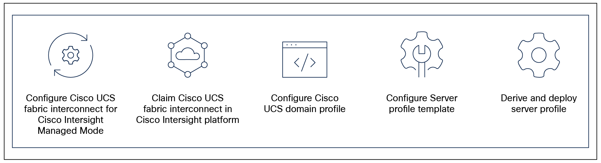
Configuration steps for Cisco Intersight Managed Mode
Setting up Cisco UCS fabric interconnects for Cisco Intersight Managed Mode
During the initial configuration, for the management mode the configuration wizard enables users to choose whether to manage the fabric interconnect through Cisco UCS Manager or the Cisco Intersight platform. Users can switch the management mode for the fabric interconnects between Cisco Intersight and Cisco UCS Manager at any time; however, Cisco UCS FIs must be set up in Intersight Managed Mode (IMM) for configuring the Cisco UCS X-Series system. Figure 19 shows the dialog during initial configuration of Cisco UCS FIs for setting up IMM.
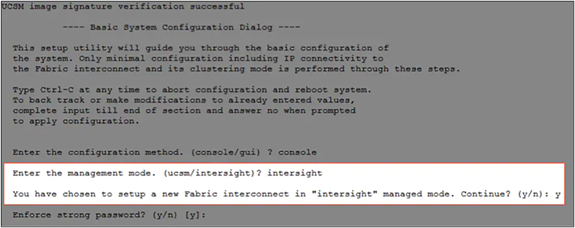
Fabric interconnect setup for Cisco Intersight Managed Mode
Claiming a Cisco UCS fabric interconnect in the Cisco Intersight platform
After setting up the Cisco UCS fabric interconnect for Cisco Intersight Managed Mode, users can claim fabric interconnects to a new or existing Cisco Intersight account. When users successfully add a Cisco UCS fabric interconnect to the Cisco Intersight platform, all future configuration steps are completed in the Cisco Intersight portal. The following screenshot shows the Cisco Intersight cloud adding fabric interconnects as targets.
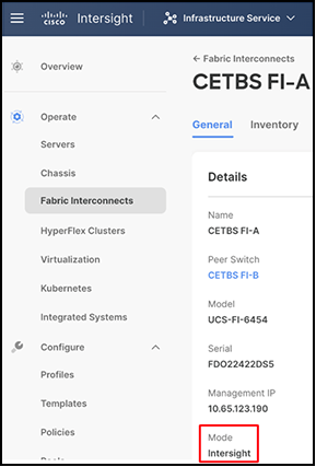
Once the Cisco UCS fabric interconnect is configured in Cisco UCS Manager managed mode or Cisco Intersight Managed Mode, a detailed information screen for the fabric interconnect will display the mode as Intersight, as shown in this screenshot:
A Cisco UCS domain profile configures a fabric-interconnect pair through reusable policies, allows configuration of the ports and port channels, and configures the VLANs and VSANs to be used in the network. It defines the characteristics of and configures the ports on the fabric interconnects. The user can assign one Cisco UCS domain profile to one fabric interconnect domain; the Cisco Intersight platform supports the attachment of one port policy per Cisco UCS domain profile.
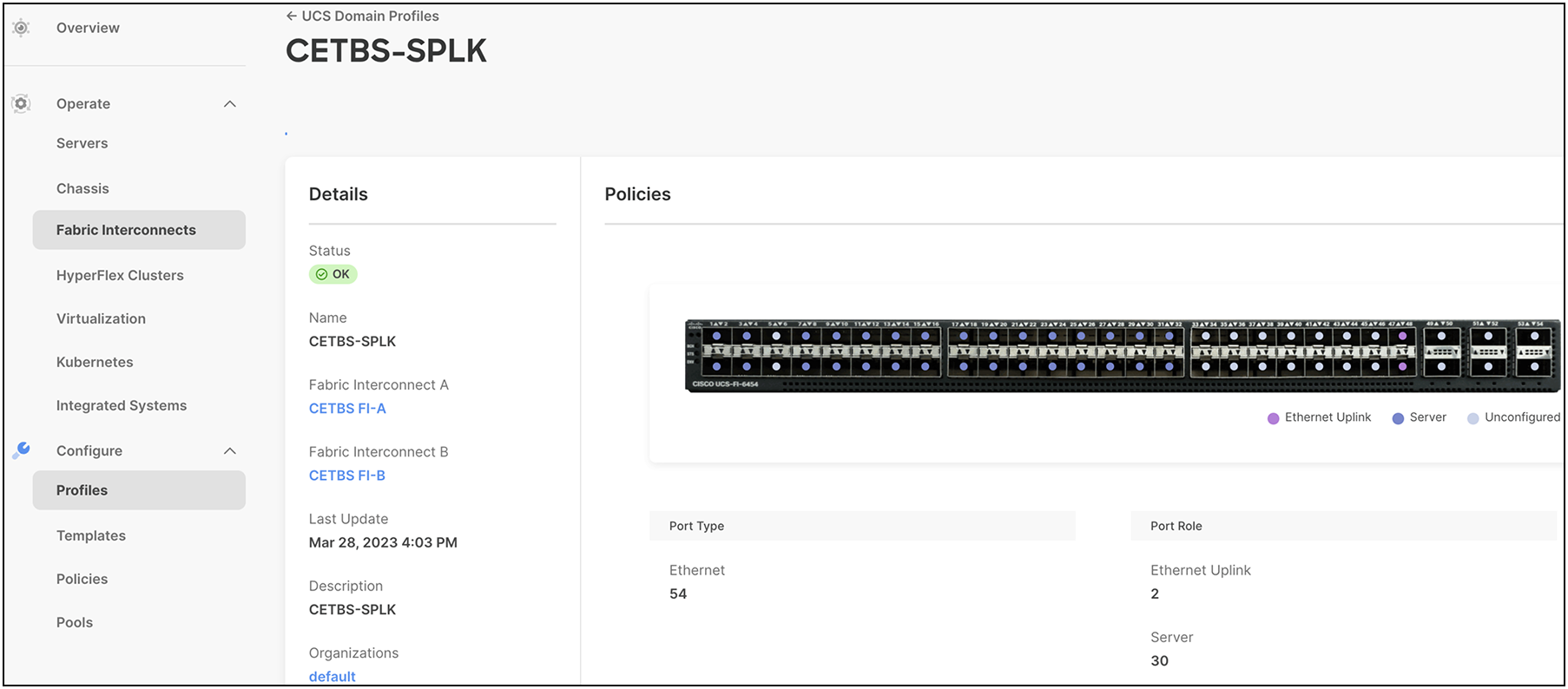
After the Cisco UCS domain profile has been successfully created and deployed, the policies, including the port policies, are pushed to Cisco UCS fabric interconnects. Users can easily clone the Cisco UCS domain profile to install additional Cisco UCS Systems. When cloning the Cisco UCS domain profile, the new Cisco UCS domains use the existing policies for consistent deployment of additional Cisco UCS Systems at scale. This screenshot shows a Cisco UCS domain profile:
The Cisco UCSX-9508 Server Chassis and Cisco UCS X210c M6 Compute Nodes are automatically discovered after successful configuration of the ports using the domain profile.
A server profile template enables resource management by simplifying policy alignment and server configuration. The user can create a server profile template by using the server profile template wizard, which groups the server policies into the following four categories to provide a quick summary view of the policies that are attached to a profile:
● Compute policies: Basic Input/Output System (BIOS), boot order, and virtual media policies
● Network policies: adapter configuration and LAN and SAN connectivity policies
◦ The LAN connectivity policy requires users to create an Ethernet network policy, an Ethernet adapter policy, and an Ethernet QoS policy.
◦ The SAN connectivity policy requires users to create a Fibre Channel network policy, a Fibre Channel adapter policy, and a Fibre Channel QoS policy. A SAN connectivity policy is required only for the Fiber Channel connectivity option. SAN connectivity policy is not used in this solution.
● Storage policies: create a VD with a large volume that can serve as the mounted disk in the configured directory for Anthos. With this, the user can make sure that the created PVs will share the new disk capacity and are isolated from the boot disk.
● Management policies: device connector; Intelligent Platform Management Interface (IPMI) over LAN; Lightweight Directory Access Protocol (LDAP); local user; network connectivity; Simple Mail Transfer Protocol (SMTP); Simple Network Management Protocol (SNMP); Secure Shell (SSH) Protocol; serial over LAN (SOL); syslog; and virtual Keyboard, Video, and Mouse (KVM) policies.
Some of the characteristics of the server profile template for Google Anthos deployment include:
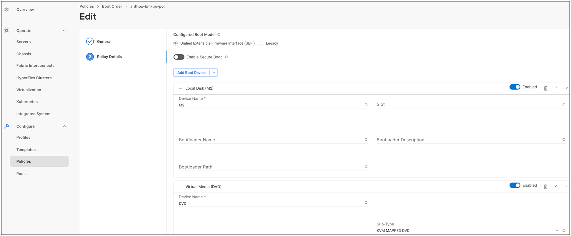
● Boot order policy configuration to boot from local storage with MRAID and M.2 controller on Intersight Managed Mode (IMM) servers.
● For more information on configuring a boot-order policy, see: https://www.cisco.com/c/en/us/td/docs/unified_computing/Intersight/b_Intersight_Managed_Mode_Configuration_Guide/b_intersight_managed_mode_guide_chapter_0110.html#id_109244.
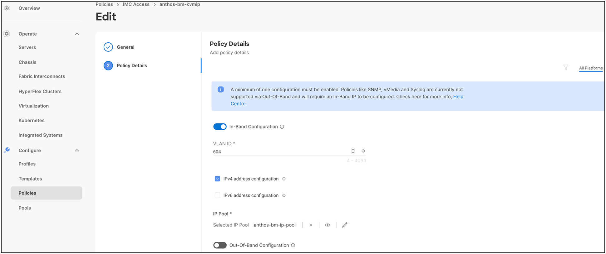
● The Cisco Integrated Management Controller (IMC) access policy defines the management IP address pool for KVM access.
● For more information on configuring a Cisco IMC access policy, see: https://www.cisco.com/c/en/us/td/docs/unified_computing/Intersight/b_Intersight_Managed_Mode_Configuration_Guide/b_intersight_managed_mode_guide_chapter_0110.html#Cisco_Reference.dita_1a59565b-14f1-4766-b2d5-0838e9e2dd19.
● Storage policy allows users to create drive groups and virtual drives, configure the storage capacity of a virtual drive, and configure the M.2 RAID controllers. For storage policy, enable M.2 RAID configuration for boot and enable MRAID/RAID controller configuration for Anthos data. This will serve as the local PV for application containers deployed on Anthos bare metal.
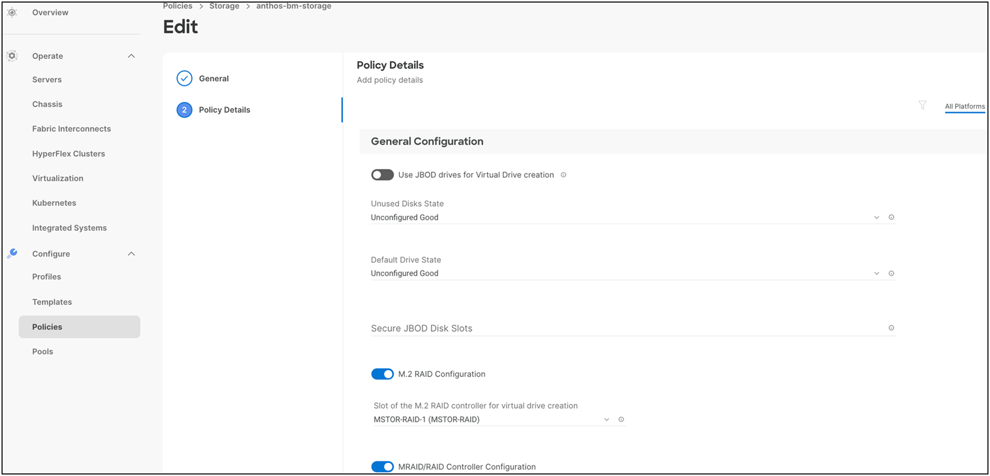
● For more information on configuring a storage policy with respect to RAID levels, drive group configuration, number of spans, VDs, etc., see: https://www.cisco.com/c/en/us/td/docs/unified_computing/Intersight/b_Intersight_Managed_Mode_Configuration_Guide/b_intersight_managed_mode_guide_chapter_0110.html#Cisco_Reference.dita_dc8f2e67-3c8c-46fa-9103-81f51f6e8387.
● LAN connectivity policy determines the connection, and the network communication resources between the server and the LAN on the network. The user can specify a static MAC address or a pool to assign MAC addresses to servers and to identify the vNICs that the servers use to communicate with the network.
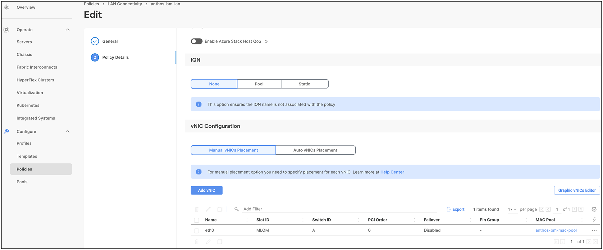
For more information on configuring a LAN connectivity policy, see: https://www.cisco.com/c/en/us/td/docs/unified_computing/Intersight/b_Intersight_Managed_Mode_Configuration_Guide/b_intersight_managed_mode_guide_chapter_0110.html#id_109623.
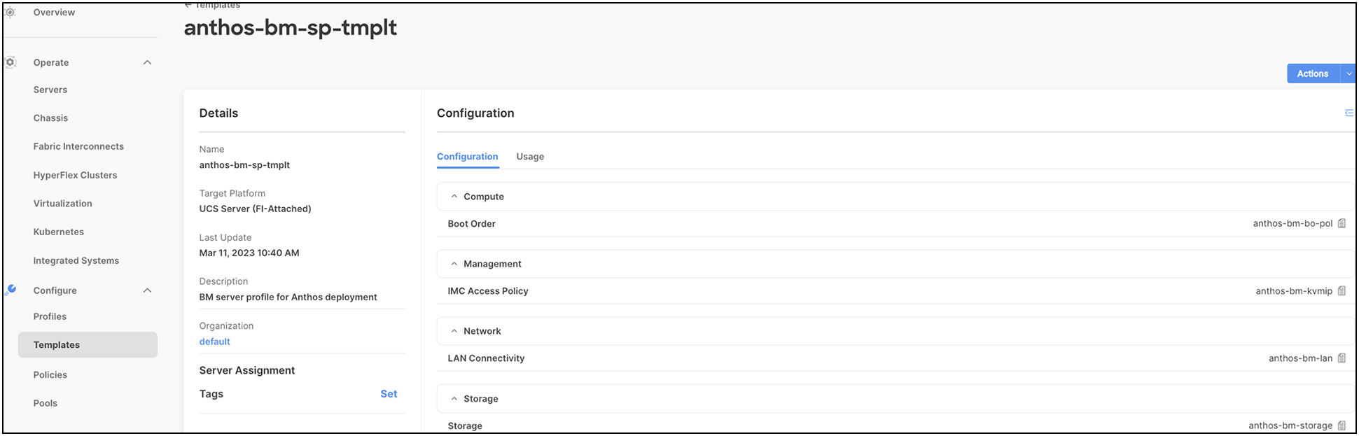
The following screenshot shows various policies associated with the server profile template:
Users can derive server profiles from the template and associate them to the bare metal servers, as shown in the following screenshot:
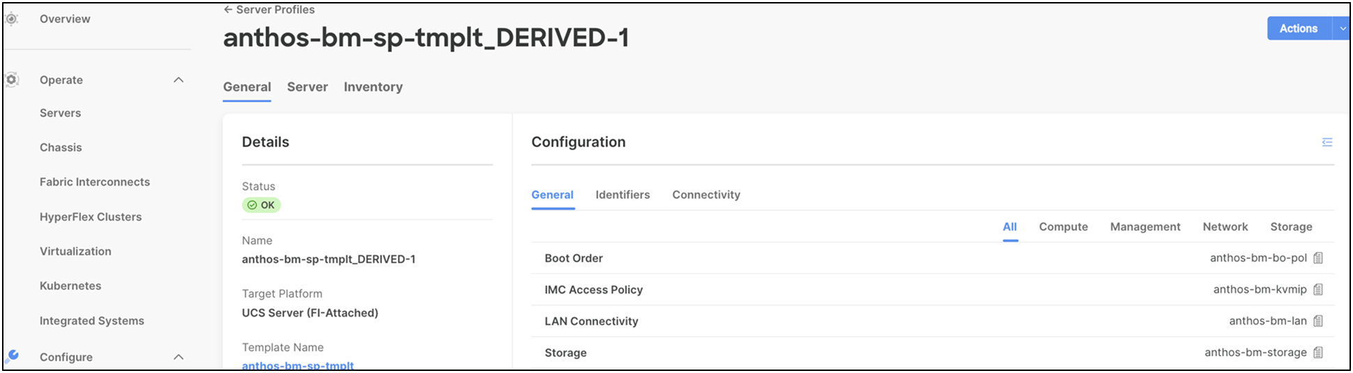
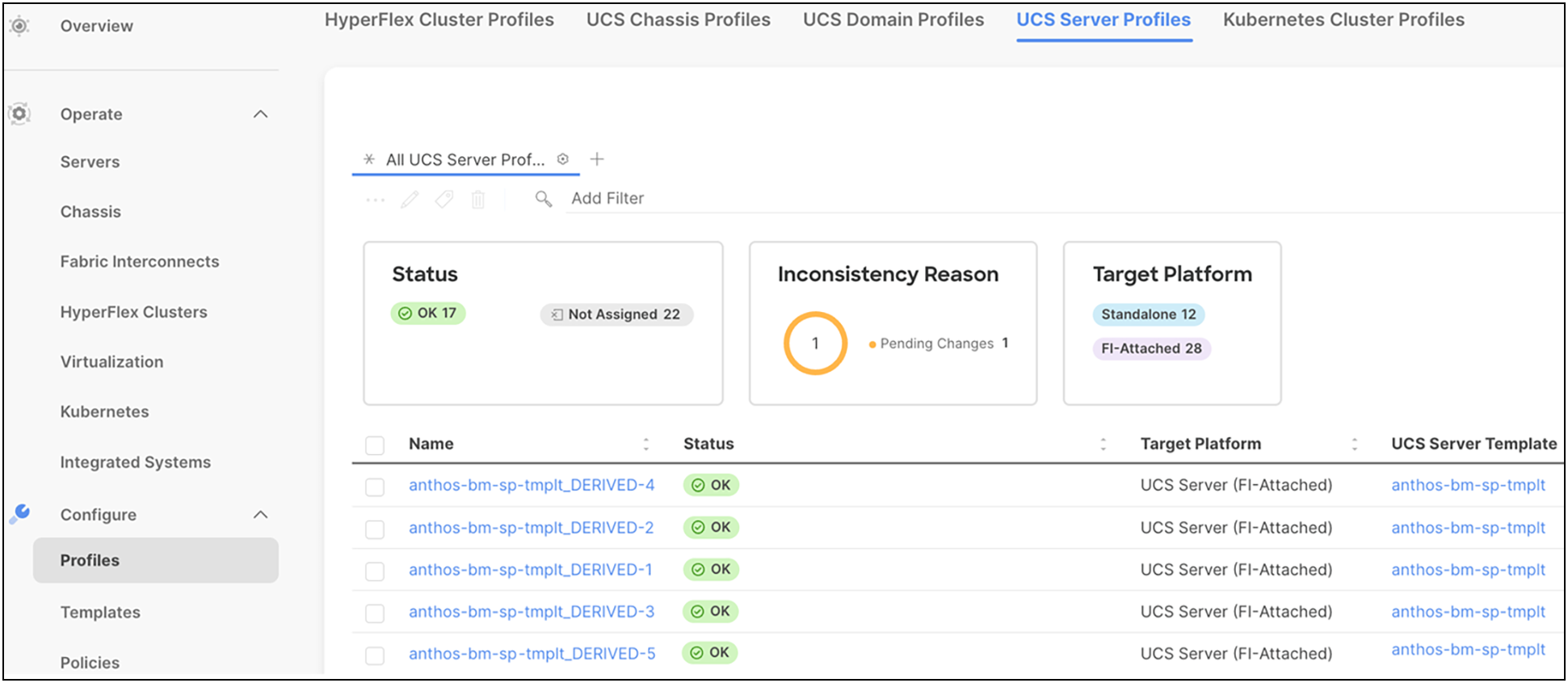
These server profiles can be customized for various workloads using the programmable interface in Cisco Intersight. A physical server can take the persona of a database server, VDI server, virtualized server, and so on, through these server profiles. Infrastructure management through Cisco Intersight is entirely stateless, and, with a unified open Application Programming Interface (API) design, users can integrate third-party platforms and tools. Users can therefore leverage server profiles and templates to manage their organization's infrastructure much more effectively and efficiently with the ease of use anywhere at any time from Cisco Intersight.
Deployment hardware and software
Anthos on bare metal allows users to install Google Kubernetes Engine (GKE) clusters to on-premises data centers without the need for a vSphere environment. Anthos on bare metal works reliably, efficiently, and cost effectively in multiple computing environments.
In this paper we have shown variety of reference architectures with best-of-class Cisco UCS servers for Google Anthos bare metal deployment. For solution testing and validation, we have deployed a 5-node Anthos cluster with 3x admin nodes for control plane HA and 2x user for running workloads on Cisco UCS X210c Compute Nodes.
The following are the prerequisites for creating an Anthos cluster on bare metal:
● Bringing up hardware for the type of Anthos cluster that users want to deploy on their bare metal.
Note: A 5-node Anthos bare metal cluster on Cisco UCS X210c M6 Computer Nodes is used for internal testing and validation.
● Setting up Google Account, GCP Service Account, and a billing-enabled GCP project.
● Setting up a Linux machine as an admin workstation configured with gcloud, gsutil, kubectl, docker, and bmctl utilities installed.
● Providing network accessibility to Google Cloud APIs – servicemanagement.googleapis.com and servicecontrol.googleapis.com.
● Selecting a supported operating system – RHEL 8.2, 8.3, 8.4, 8.5, 8.6, CentOS 8.2, 8.3, 8.4, 8.5, Ubuntu 18.04*/20.04 LTS.
Note: For our internal testing and validation, we have used RHEL 8.5.
Note: *Ubuntu version 18.04 needs to be on Linux kernel 5.4 or above. To ensure compatibility, it is recom-mended for users to install the [Ubuntu Hardware Enablement (HWE) kernel] (https://ubuntu.com/kernel/lifecycle#installation-18-04){: external} and upgrade it to the latest supported HWE version for Ubuntu 18.04.
Hardware resource requirements
The admin workstation requires significant computing power, memory, and storage to run tools and store the resources associated with cluster creation and management. By default, the cluster upgrade and cluster create operations use a bootstrap cluster. When a bootstrap cluster is used, there is a significant increase in CPU and memory usage.
And for the cluster nodes, Anthos has recommended hardware resource requirements based on two profiles, called a default profile and an edge profile. As the name suggests, a default profile can be used on all types of Anthos clusters, and an edge profile is recommended for edge devices with reduced system resource requirements.
Table 2. Default profile minimum and recommended hardware requirements for running Anthos on bare metal
| Resource |
Minimum |
Recommended |
| CPUs |
4 cores |
8 cores |
| RAM |
32 GiB |
64 GiB |
| Storage |
128 GiB |
256 GiB |
Local storage provisioning for Anthos bare metal deployments
Anthos on bare metal clusters provides two options for configuring local PVs in the cluster:
● LVP share: uses directories in a shared-file system
● LVP node mount: uses dedicated disks
Note: For our testing and validation of Anthos bare metal clusters, LVP node mount is used.
In this option, the storage class creates a local PV for each mounted disk in the configured directory. Each PV maps to a disk with capacity equal to the underlying disk capacity.
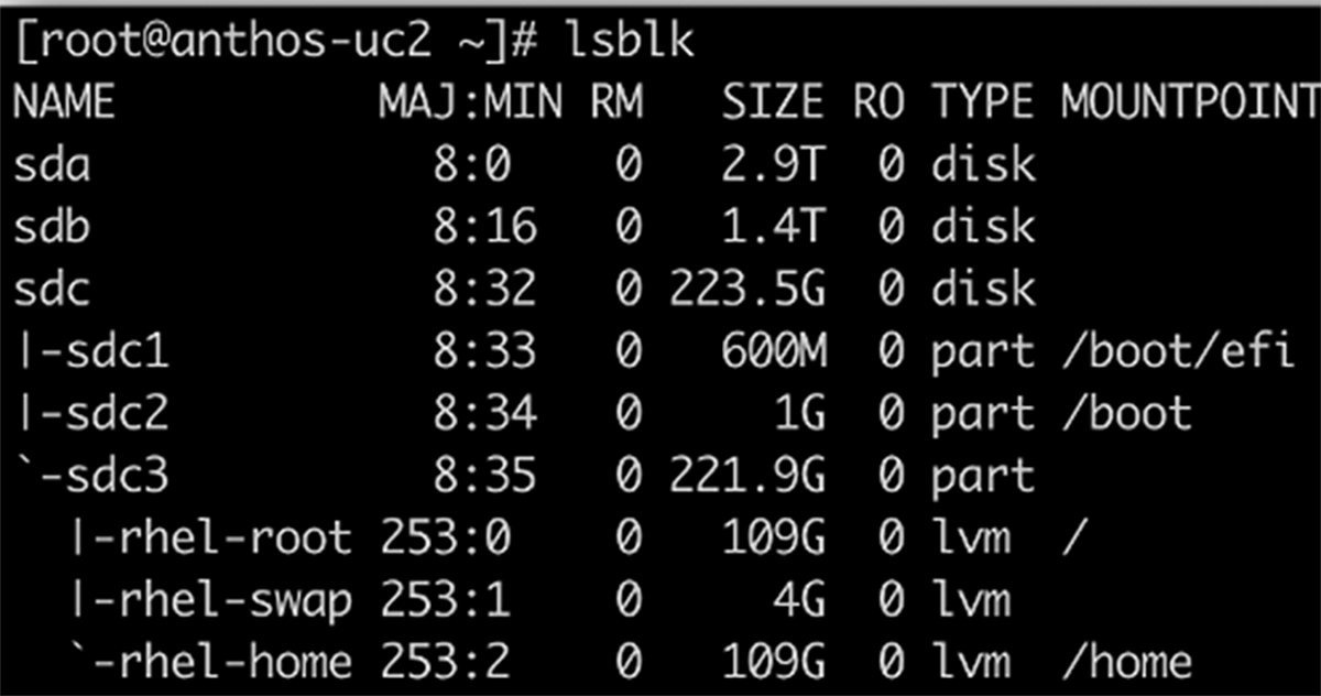
1. On the cluster nodes, format and mount the disk under the defined path. This can also be done be-fore or after cluster creation.
lsblk
2. Format the disk; for example, with a single ext4 file system:
mkfs.ext4 -m 0 -E lazy_itable_init=0,lazy_journal_init=0,discard /dev/DEVICE_ID
3. Under the configured path, create a directory as the mount point for the new disk:
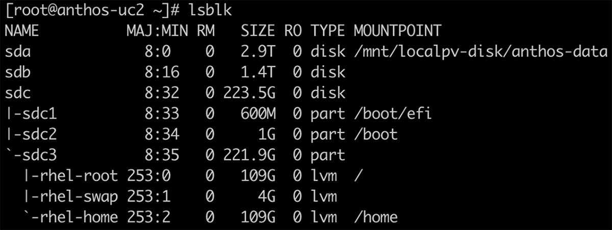
mkdir -p /mnt/localpv-disk/<MNT_DIR>
Note: /mnt/localpv-disk/anthos-data is the mount point created for the Anthos bare metal deployment in our setup.
4. Mount the disk:
mount -o discard,defaults /dev/DEVICE_ID /mnt/localpv-disk/<MNT_DIR> &&
chmod a+w /mnt/localpv-disk/<MNT_DIR>
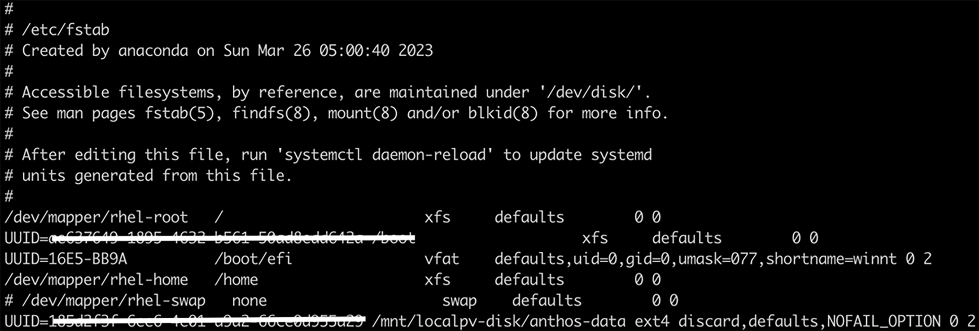
5. Add the disk to the /etc/fstab file, so that the device automatically mounts again when the instance restarts:
# Backup the current /etc/fstab file
sudo cp /etc/fstab /etc/fstab.backup
# Use the blkid command to find the UUID for the zonal persistent disk
sudo blkid /dev/DEVICE_ID
# Edit /etc/fstab file: create an entry that includes the UUID
UUID=<UUID_VALUE> /mnt/localpv-disk/<MNT_DIR> ext4 discard,defaults,NOFAIL_OPTION 0 2
Note: While editing the Anthos bare metal deployment config file, the user must make sure the node mount is specified under lvpNodeMounts in the yaml file.
Deploying Anthos on bare metal requires knowledge with Linux command-line skills, and an understanding of the existing network topology.
Note: The time required to complete an Anthos on bare metal deployment varies based on network speed and familiarity with the tools.
Note: Before starting an Anthos deployment, ensure that all of the prerequisites listed in the earlier sections in this paper have been met.
Create a Google Cloud project and a Google Cloud billing account.
During installation, users must provide the following credentials:
● The private SSH keys needed to access cluster node machines.
● If a non-root user, the cluster node machine login name.
Complete the following instructions to configure the Linux administration machine referred to as an admin workstation:
1. Install the gcloud and gsutil tools, which are included in the Google Cloud SDK. For detailed information, see https://cloud.google.com/sdk/docs/install .
2. Update the Google Cloud SDK.
gcloud components update
3. Access the Google account to manage services and service accounts.
gcloud auth login
4. Set the default project. Replace PROJECT_ID with the Google Cloud project ID.
gcloud config set project PROJECT_ID
5. Use gcloud to install kubectl.
gcloud components install kubectl
6. Enable APIs associated with the Google Cloud project.
Note: In order to enable APIs, the user should have one of the following roles in the Cloud project: roles/owner, roles/editor, or roles/serviceusage.serviceUsageAdmin.
Anthos clusters on bare metal connect users’ clusters to Google Cloud. This connection lets them manage and observe their clusters from the Google Cloud console by using:
◦ Connect – to connect the user’s bare metal cluster to Google Cloud. This enables the user to access the cluster and workload management features, including a unified user interface - Google Cloud console, for interacting with the cluster.
◦ Logging and monitoring – to view logs and metrics from the cluster in the Google Cloud console.
Users need to enable the necessary Google services for accessing their cloud project and create service accounts with necessary roles:
● gcr service account: Anthos clusters on bare metal use this service account to download container images from the container registry.
● connect-agent service account: Google Connect Agent uses this service account to maintain a connection between the user’s on-premises cluster and Google Cloud.
● connect-register service account: Google Connect Agent uses this service account to register the user’s clusters with Google Cloud.
● cloud-ops service account: Google Connect Agent uses this service account to export logs and metrics from the clusters to Google Cloud Logging and Google Cloud Monitoring.
● storage-agent service account: bmctl uses this service account to automatically store snapshots of clusters to Google Cloud Storage.
Note: JSON key files for each service account should be downloaded and saved into the baremetal directory. The user must create a baremetal directory and run all the cluster creation commands from the baremetal directory. Users can then add references to the JSON key files to the appropriate cluster config files. For de-tailed steps on creating service accounts, see https://cloud.google.com/anthos/clusters/docs/bare-metal/latest/installing/configure-sa
For more information on bringing up an admin workstation node, see: https://cloud.google.com/anthos/clusters/docs/bare-metal/latest/installing/workstation-prerequisites
Create an Anthos bare metal cluster
Users need to follow these steps to create an Anthos bare metal cluster:
1. To create a cluster, user should:
● Use bmctl to create a config file
● Edit the config file to add the required cluster and network details
● Use bmctl to create the cluster from the config file
2. To create a config file, and enable service accounts and APIs automatically, users must make sure they are in the baremetal directory, and issue the bmctl command with the following flags:
./bmctl create config -c <CLUSTER_NAME> --enable-apis --create-service-accounts --project-id=<PROJECT_ID>
Note: The command above creates a config file under the baremetal directory at the following path: bmctl-workspace/cluster1/cluster1.yaml.
3. Users should edit the config file to specify node and network requirements. A sample config file is provided, and each field in the file has been documented for the user’s reference at: https://cloud.google.com/anthos/clusters/docs/bare-metal/latest/quickstart .
4. Once updated to reflect all the cluster requirements, the user can run the bmctl command. This command runs preflight checks on the cluster config file before it creates a cluster. If the checks are successful, bmctl creates the cluster.
./bmctl create cluster -c <CLUSTER_NAME>
Note: The user must ensure they are in the baremetal directory before running the above command.
Once the cluster is successfully created, users can run kubectl command to see information about the new cluster. During cluster creation, kubeconfig file is written to bmctl-workspace/CLUSTER_NAME/CLUSTER_NAME-kubeconfig.
Kubectl –kubeconfig bmctl-workspace/cluster1/cluster1-kubeconfig get nodes
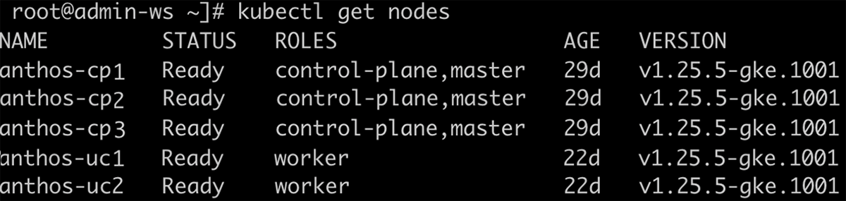
Note: Users can export their kubeconfig file to avoid adding the kubeconfig flag in the kubectl commands. For example: export KUBECONFIG=/root/baremetal/bmctl-workspace/anthosbm-cluster/anthosbm-cluster-kubeconfig.
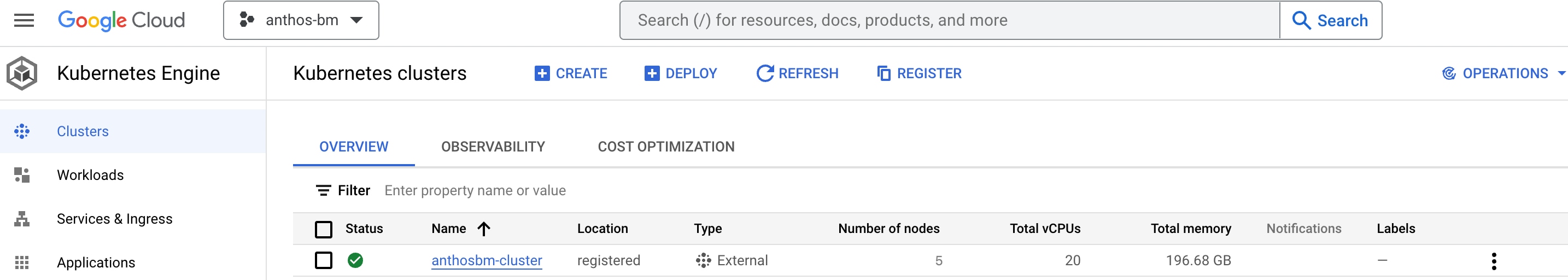
Manage the cluster in the Google Cloud Console
If the cluster creation was successful, the user can view the cluster registered in the Google Cloud console under Kubernetes Engine > Clusters. However, to log in to the registered Anthos cluster in Google Cloud, the user needs to authenticate either using Google Cloud login or using a bearer token, or with a third-party identity.
Many kinds of bearer tokens, as specified in Kubernetes authentication, are supported. The easiest method is to create a Kubernetes service account (KSA) in the cluster and use its bearer token to log in.
For details on creating a KSA bearer token, see: https://cloud.google.com/anthos/identity/setup/bearer-token-auth.
Once the bearer token is generated and applied, the user will be logged in to the registered Anthos bare metal cluster, as shown in the following screenshot.
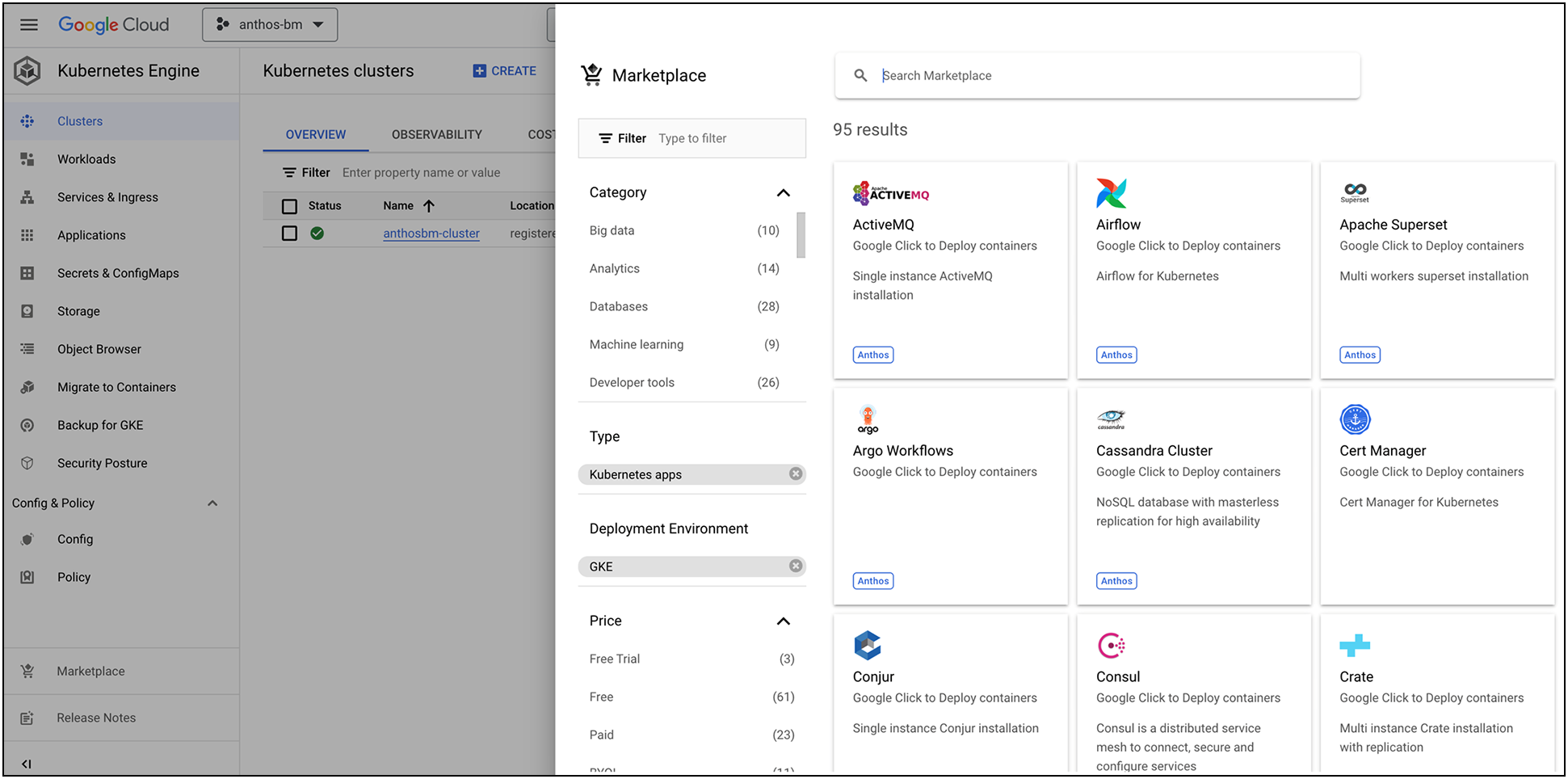
After the cluster is logged in, users can monitor workloads, resource utilization, etc., and also use Google Cloud Marketplace to deploy needed applications.
Google Cloud’s Anthos bare metal on Cisco UCS is an excellent solution for organizations investing in bare metal infrastructure in the cloud. This solution provides exceptional value for customers looking for predictable performance, enhanced security, high scalability, and reliability. With local disks of Cisco UCS servers serving as persistent volumes to containerized enterprise applications, customers can expect nothing less than high performance with low latencies. From the data center to the edge, leveraging Cisco UCS platform servers powered by Intel Xeon scalable processors, customers can modernize cloud operations with minimum effort and seamlessly adopt hybrid-cloud models for their organizations. By extending the potential of Google Cloud Anthos into the data center powered by Cisco UCS, customers can realize the benefits of a highly available, easily scalable, and completely managed fleet supporting their Kubernetes workloads.
For more information on Cisco UCS servers, Cisco Intersight, or Google Anthos on bare metal, refer to the following links:
● Cisco UCS X-Series Modular System: https://www.cisco.com/c/en/us/products/collateral/servers-unified-computing/ucs-x-series-modular-system/solution-overview-c22-2432175.html?ccid=cc002456&oid=sowcsm025665.
● Cisco UCS C240 M6 Rack Server: https://www.cisco.com/c/en/us/products/collateral/servers-unified-computing/ucs-c-series-rack-servers/ucs-c240-m6-rack-server-ds.html.
● Cisco Intersight Managed Mode Configuration Guide: https://www.cisco.com/c/en/us/td/docs/unified_computing/Intersight/b_Intersight_Managed_Mode_Configuration_Guide.html.
● Google Cloud’s Anthos on Bare Metal: https://cloud.google.com/anthos/clusters/docs/bare-metal/latest/concepts/about-bare-metal.