Spectralink VIEW Certified Configuration Guide for Catalyst 9800-CL Wireless Controller
Available Languages
Bias-Free Language
The documentation set for this product strives to use bias-free language. For the purposes of this documentation set, bias-free is defined as language that does not imply discrimination based on age, disability, gender, racial identity, ethnic identity, sexual orientation, socioeconomic status, and intersectionality. Exceptions may be present in the documentation due to language that is hardcoded in the user interfaces of the product software, language used based on RFP documentation, or language that is used by a referenced third-party product. Learn more about how Cisco is using Inclusive Language.
Spectralink’s Voice Interoperability for Enterprise Wireless (VIEW) Certification Program is designed to ensure interoperability and high performance between Versity smartphones and 84-Series handsets and WLAN infrastructure products.
The products listed below have been tested in Spectralink’s lab and have passed VIEW Certification.
Table 1. Cisco Supported Product and Feature Summary
| Manufacturer: |
Cisco Systems Inc.: www.cisco.com |
|
| Certified products: |
Controllers: Cisco Catalyst 9800-CL Wireless |
Access points: Cisco Aironet 1560 Series Cisco Aironet 2800 Series Cisco Aironet 3800 Series Cisco Aironet 4800 Series Cisco Catalyst 9100 Access Points |
| Access point radio(s): |
2.4 GHz (802.11b/g/n), 5 GHz (802.11a/n/ac) |
|
| Security: |
None, WPA2-PSK and WPA2-PSK with FT-PSK, WPA2-Enterprise (EAP-FAST, EAP-TLS, and PEAPv0/MSCHAPv2) with Cisco Centralized Key Management (CKM) OKC, and FT-802.1X (802.11r) |
|
| QoS: |
Wi-Fi Standard for Spectralink Versity, 84-Series |
|
| Network topology: |
Switched Ethernet (recommended) |
|
| Access point and WLC software versions approved: |
16.12.2s for 380x, 1542,1852, 9130, 9115, 9117, 9120, 9105 with 9800CL 17.3.5b for 1852,2800,3800,4800,9105,9117,9120,9130 with 9800CL |
|
Table 2. Smartphone Client Test Information
| Smartphone* models tested: |
Versity smartphone 92/95/96 |
|
| Smartphone radio mode: |
802.11b/g and 802.11bgn |
802.11a, 802.11an, and 802.11ac |
| Meets VIEW minimum call capacity per access point: |
10 calls |
12 calls |
Table 3. Handset Client Test Information
| Handset models tested: |
Spectralink 84-Series handset |
|
| Handset radio mode: |
802.11b/g and 802.11bgn |
802.11a and 802.11an |
| Meets VIEW minimum call capacity per access point: |
8 calls |
10 calls |
The following features can be turned on in the network using the directions in this guide. However, not all handset or Access Point (AP) models support the features. See the notes for a more detailed description.
Packet aggregation
A-MSDU and A-MPDU (Aggregate MAC Service Data Unit and Aggregate MAC Protocol Data Unit) packet aggregation methods improve throughput in networks. If 802.11n is disabled in the 84-Series handsets, they are compatible with aggregation in the network. Versity smartphones implement aggregation. Instructions for disabling 802.11n are found in the administration guide for the 84-Series.
DTPC
Dynamic Transmit Power Control (DTPC) is a Cisco proprietary method of matching phone power to AP power. In the 84-Series handsets, it is selected by choosing the Auto power setting in the handset configuration. Versity is in Auto mode by default. This feature is not yet implemented in the Aironet 2800 and 3800 Series APs.
802.11r (Fast Transition)
Fast Transition (FT) roaming (802.11r) is implemented in the Versity smartphones. The preferred method for fastest roaming in the other handset models is to use Cisco CKM. SSIDs are compatible with all models if FT is enabled and multiple radio buttons are checked in the WLAN > Security section, as described in this guide.
WMM-PS
Versity does not have to use Wi-Fi Multimedia Power Save (WMM-PS), but the other handsets must have WMM-PS only. This is covered by setting WLAN settings to WMM Allowed instead of Required.
802.11ac
Versity is an 802.11ac device. The other handsets should be used as 802.11a/b/g/n devices. All are compatible with 802.11bgn and 802.11ac networks as implemented by the Cisco versions listed here. One exception: The Aironet 3600 Series snap-in 802.11ac module is not compatible in 802.11ac mode. It works with the handsets in other modes.
802.11ax
Versity smartphones and the 84-series can operate in a network using 6 GHz frequencies, but they will not use the 6 GHz frequency. 2.4 GHz or 5 GHz must be enabled to support the Versity or 84-series handsets.
Other notes
● For best operation, the RRM/Tx Power Control (TPC) should be set to Fixed or On Demand (during a low usage period) and the RRM/DCA Algorithm should be set to Freeze or OFF. The handsets are not incompatible with these features, but if used frequently, they will cause long roams and asymmetric coverage regions that will result in choppy calls during caller movement. Channel Switching is not yet implemented in Spectralink handsets at this time.
● Multicast by VLAN is not compatible with the PTT feature in the handsets.
● In the WMM/QoS mode, it is important not to use the Load Based CAC Method.
● ipv6 operation has not been tested.
● Currently for Versity, multicast must be set up to send traffic for the PTT multicast address on all switch ports that may be connected to Versity phones without expecting query responses.
● The 84-series and Versity smartphones do not support WPA3 modes. They should not be attached to an SSID that has WPA3 in its security as some versions of the phone software may seem to join the SSID and not operate correctly.
● The Cisco proprietary CCKM fast roaming method will be deprecated soon. FT (802.11r) for Versity and OKC for the 84-series are recommended.
All Spectralink support documents are available at https://support.spectralink.com .

To go to a specific product page
Select the Product Category and Product Type from the drop-down lists, and then select the product from the next page. All resources for that particular product are displayed by default under the All tab. Documents, downloads, and other resources are sorted by the date they were created, so the most recently created resource is at the top of the list. You can further sort the list by the tabs across the top of the list to find exactly what you are looking for. Click the title to open the link.
Support documents
Access point configuration guides show you how to correctly configure APs and WLAN controllers (if applicable) and identify the optimal settings that support Spectralink smartphones. The guides are available on the View Certified page on the Spectralink support site at https://support.spectralink.com/view.
Spectralink Versity software and support documents are available on the Spectralink support site at https://support.spectralink.com/versity.
Spectralink Application Management (SAM) software and support documents are available on the Spectralink support site at https://support.spectralink.com/sam.
Spectralink 84-Series system documents are available on the Spectralink support site at https://support.spectralink.com/products/wi-fi/spectralink-84-series-wireless-telephone.
Release notes accompany every software release and provide the new and changed features and resolved issues in the latest version of the software. Please review these for the most current information about your software.
Note: Converting autonomous APs to Lightweight mode
This document does not cover the steps involved in converting autonomous APs to Lightweight mode such that they can be controlled by the Cisco WLCs. Please contact Cisco's Customer Support at www.cisco.com for instructions on this procedure. Once the APs are converted, this document can be used to provision APs.
Note: RADIUS server configuration
This document does not cover the steps involved to configure a RADIUS server required for using WPA2-Enterprise or Cisco Fast Secure Roaming (FSR) security types.
● Installation and configuration guides for Cisco wireless LAN controllers can be found on Cisco’s website.
● For other assistance, contact either Cisco’s or Spectralink’s customer service at:www.cisco.com or www.Spectralink.com.
Spectralink 84 Series handsets only support Wi-Fi Standard QoS. The handsets are compatible with both networks configured with CCX (Cisco Compatible Extensions) and networks that are not configured with CCX, but they have not been CCX certified.
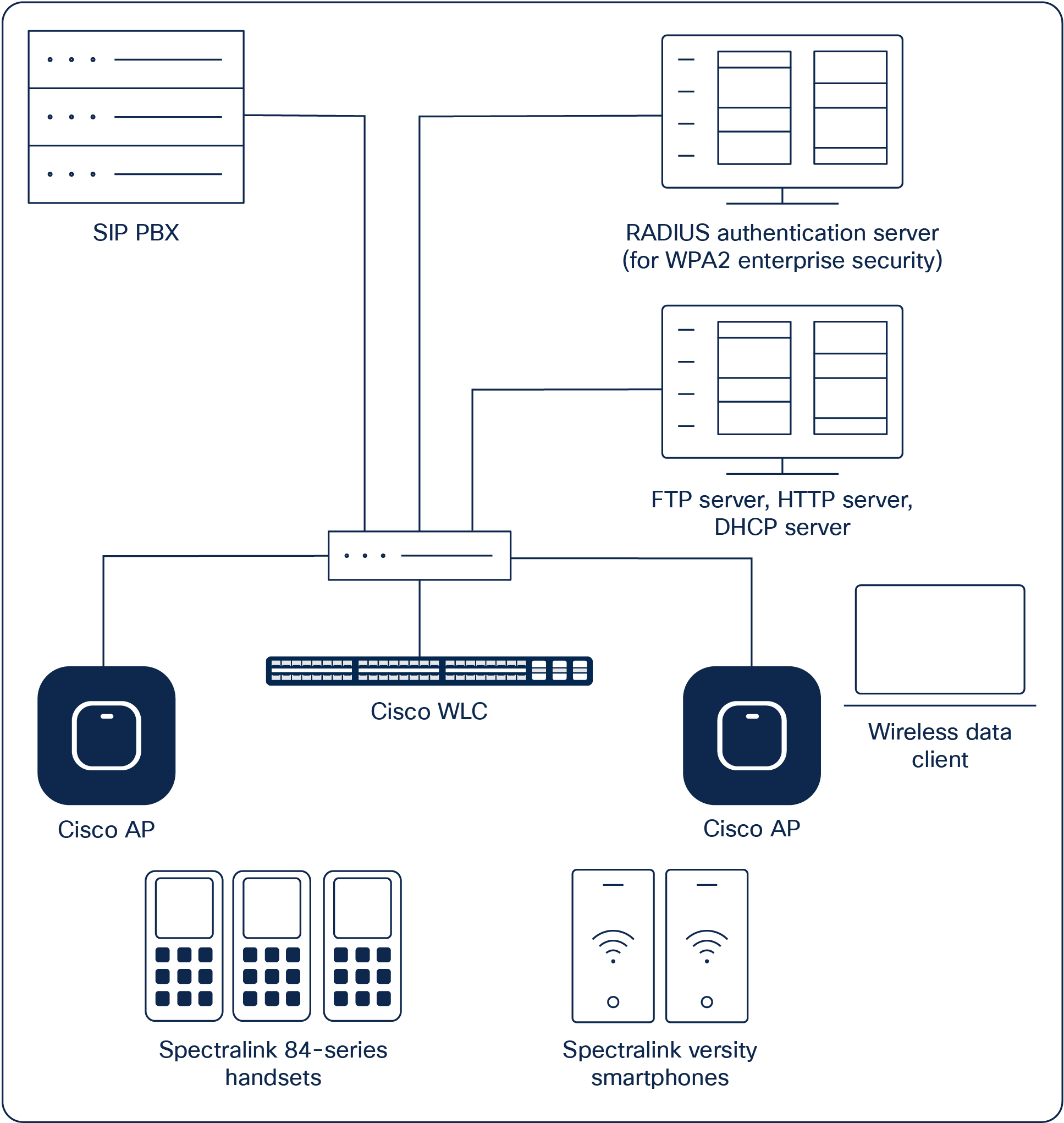
Example network topology
Note: Example configuration shown
This is a modified diagram, and not all components are shown for every system type.
Chapter 2: Configuration instructions
Configuring a new controller starting from factory defaults
Initial provisioning of the controller is done via the Command-Line Interface (CLI). This document covers the setup when the controller has been deployed in a VMware ESXi environment.
1. Select the virtual machine hosting your controller, and right-click to edit the settings.
2. Power on the controller.
3. The status of the controller’s boot process will appear as the controller is powering up. Once the controller is running, it will prompt you to run the Startup Wizard.
4. The Startup Wizard provides an easy way to perform initial controller setup and provisioning. Refer to the Installation and Startup Guide for the appropriate controller, found at Cisco’s website. This document contains a detailed explanation of using the Startup Wizard for the Catalyst 9800-CL. Once the controller has been configured via the Startup Wizard, the remaining configuration can be configured through the switch’s web interface using a web browser.
5. If necessary, the controller can be reset to factory defaults. To do this, reboot the controller and then type Recover-config at the CLI. This works only before the first time a user logs in via the console factory reset.
A few advanced commands must be set from the CLI after the rest of the controller has been configured. These are noted in the instructions below.
Connecting to the controller via a browser
1. Connect to the WLC by pointing your browser to the URL https<IP_Addr> (where <IP_Addr> is the IP address of the management interface of the WLC).
2. Click the Login prompt. Once logged in properly, you will see a page similar to the one displayed below.
3. Click the Menu icon in the top left corner to expand the menu.
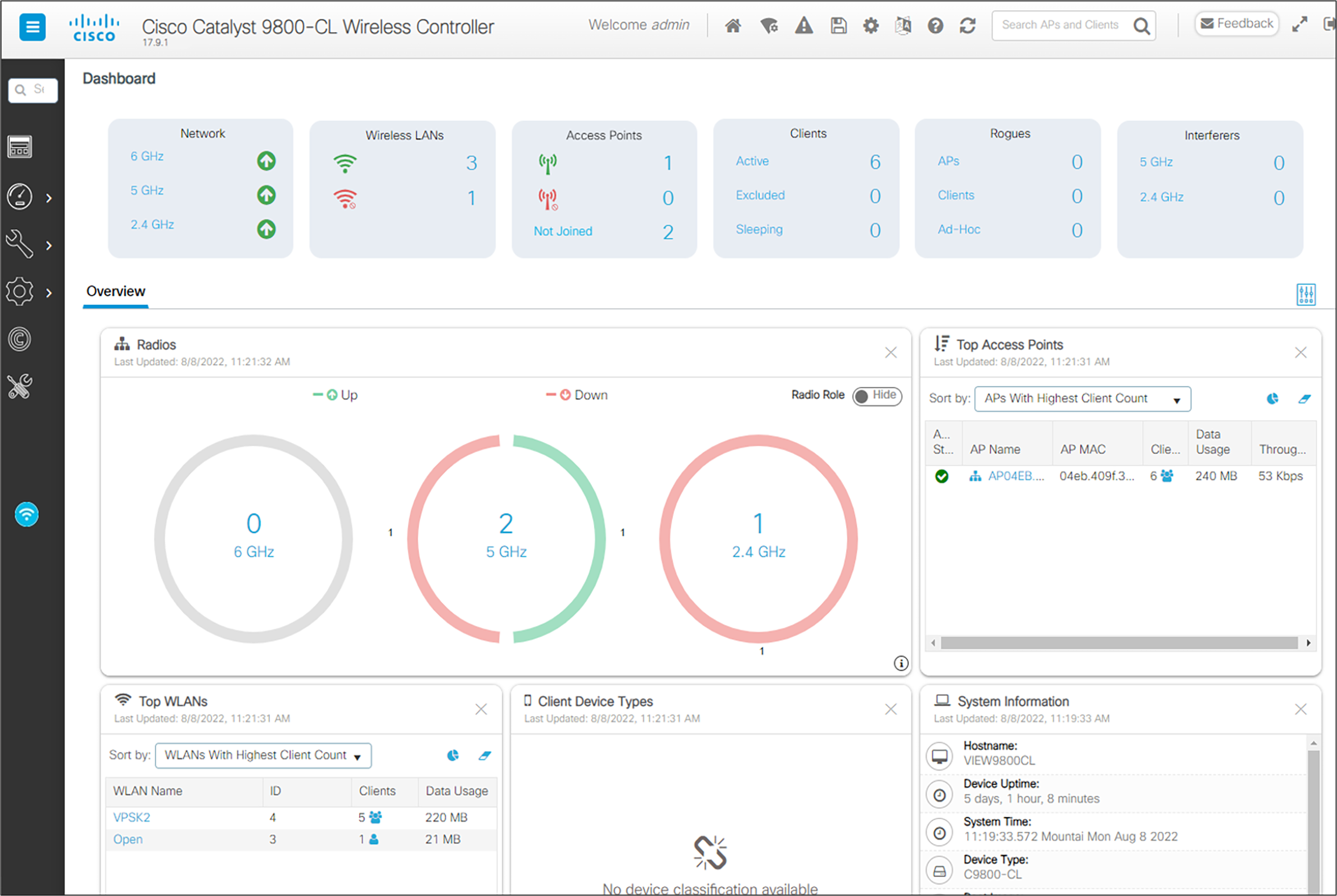
4. The main menu is now available.
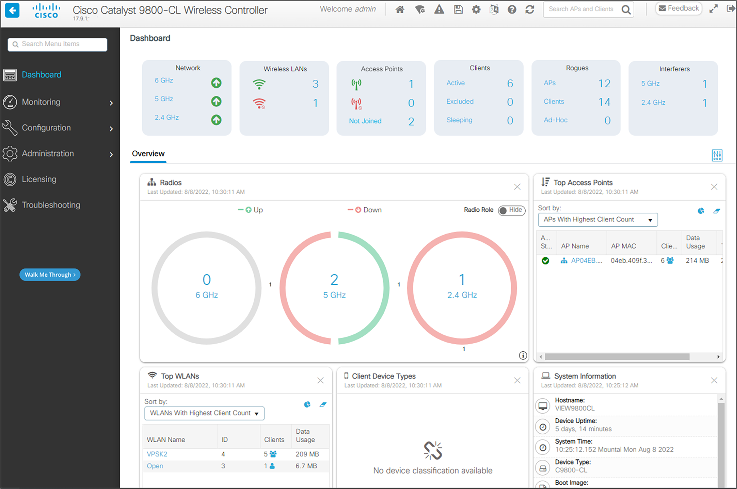
1. The current software version of the controller is displayed below the device name in the top left corner.
2. Download the appropriate software for your controller model from the Cisco website.
3. From the main menu, click Administration.
4. In the navigation pane, click Software Management and select Software Upgrade.
5. Fill in the parameters:
a For Upgrade Mode, select INSTALL.
b For Transport Type, select the desired method, either a server or a local file. Set up the SFTP, FTP, or TFTP server as necessary.
c Fill in the parameters necessary for the transport type. Note that the file path includes the file name.
6. Click Download and Install and allow a few minutes for the download to complete. Preload the AP images to save down time for the network if desired by checking AP Image Predownload. The right side of the screen will show progress. Log messages can also be displayed if desired on the right side of the screen.
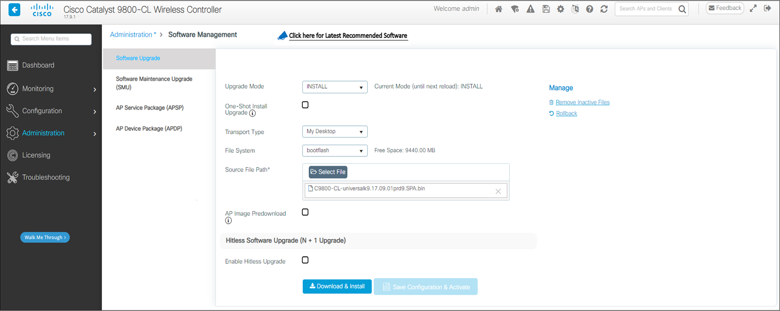
7. Once the download is complete click Save Configuration and Activate.
8. When the activation is complete, test the configuration out to see if it is acceptable. When the operation is deemed acceptable, click Commit to make the change permanent.
The initial setup of the controller is shown below.
Note: Example only
The setup instructions outlined in this document are for the configuration shown in the diagram only. Your configuration may differ, and the appropriate adjustments must be made.
Note: The WLC will provision the APs
It is not necessary to configure each AP individually. The WLC is capable of provisioning the APs.
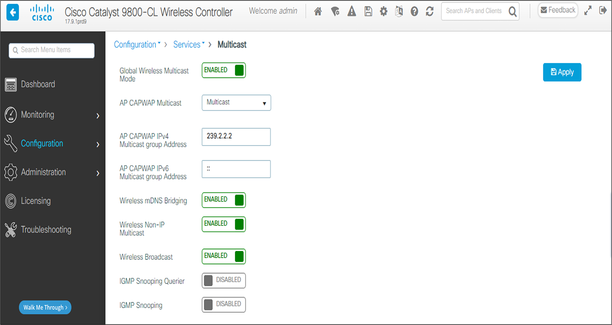
1. From the main menu, click Configuration. Under Services, click Multicast.
2. Enable the following options: Global Wireless Multicast Mode, Wireless mDNS Bridging, Wireless Non-IP Multicast, and Wireless Broadcast.
3. Set the AP Capwap Multicast to Multicast and enter a multicast IP address that is currently not being used on your network for the Multicast Group Address.
4. Click the Apply button.
5. Click Save Configuration.
Note: Send Multicast Always
Spectralink phones use a dense multicast model. For more information, see the technical note PTT Call Flow on the Spectralink support site.
As the APs are connected to the network, they should automatically find the controller via the CAPWAP discovery algorithms. The Dynamic Host Configuration Protocol (DHCP) server will assign each AP an IP address.
The Wireless interface configuration should include the DHCP server you have configured. Alternately, you can configure the DHCP server internally on the controller to hand out leases to the connected clients.
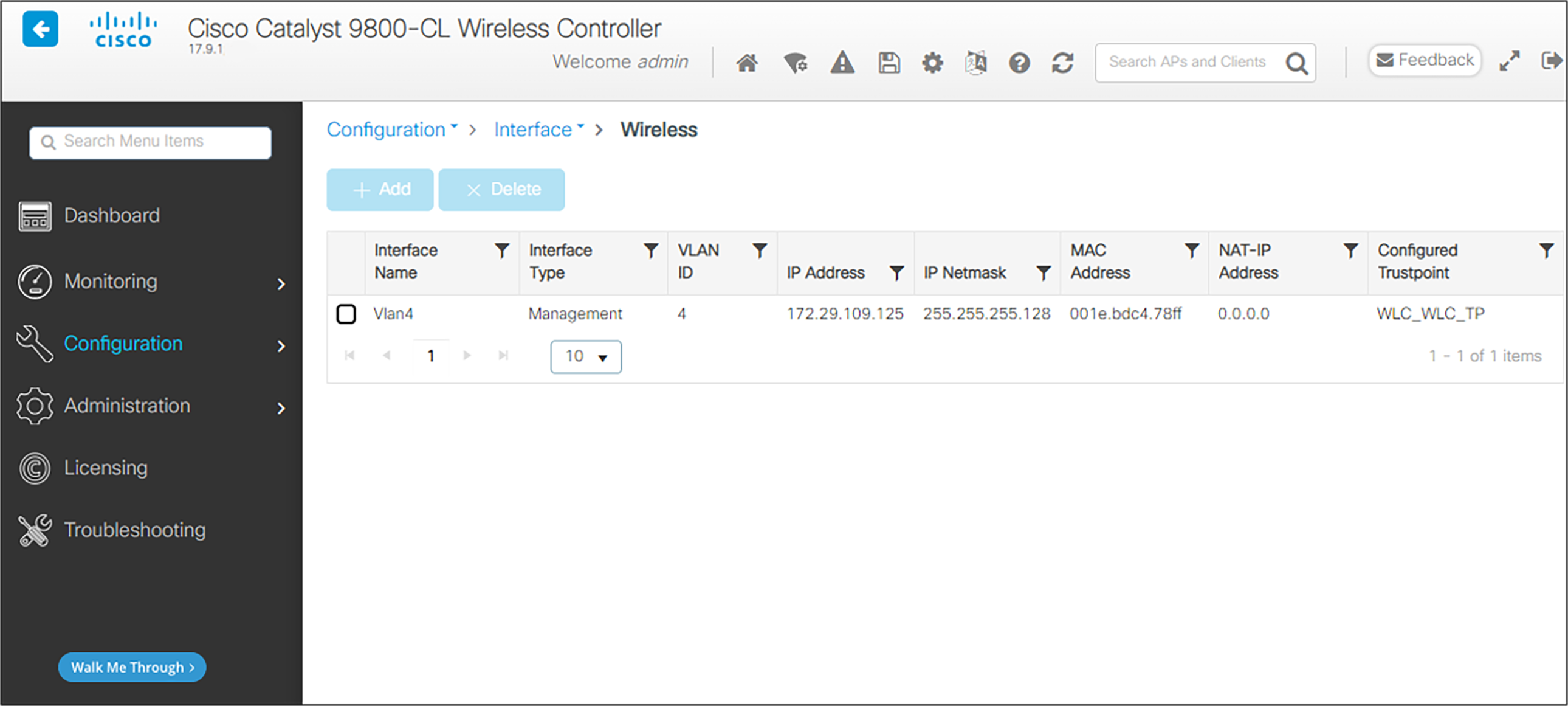
1. From the main menu, click Configuration.
2. In the navigation pane, click Wireless under Interface. Verify that the proper IP address and netmask are assigned to the interface.
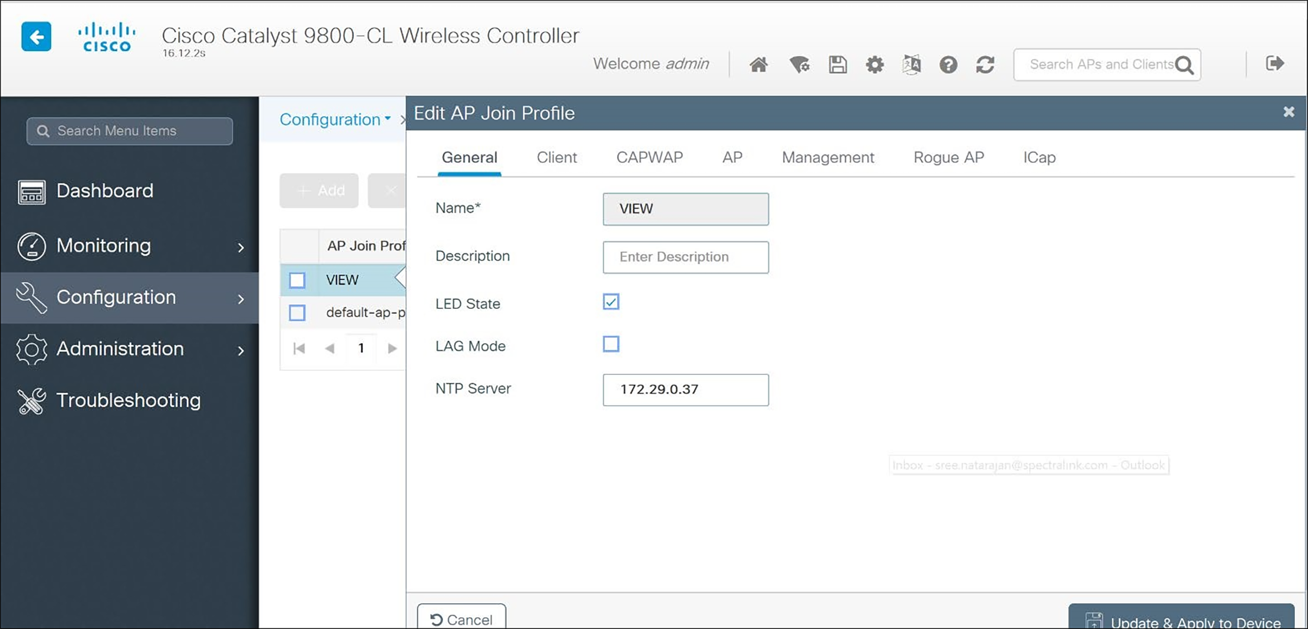
3. Further changes to AP Join parameters can be made by accessing Configuration and selecting AP Join under Tags and Profiles.
If it is desired to use WPA2-Enterprise security, it is necessary to define a RADIUS server.
1. From the main menu, click Configuration. Select AAA under Security.
2. Select RADIUS in the left pane.
3. Click +Add.
4. Enter Name of the RADIUS server
5. Enter the IP Address of the RADIUS server in the Server IP Address field.
6. Set Key Type to Clear Text.
7. Enter the Shared Secret from the RADIUS server in the Key and Confirm Key fields.
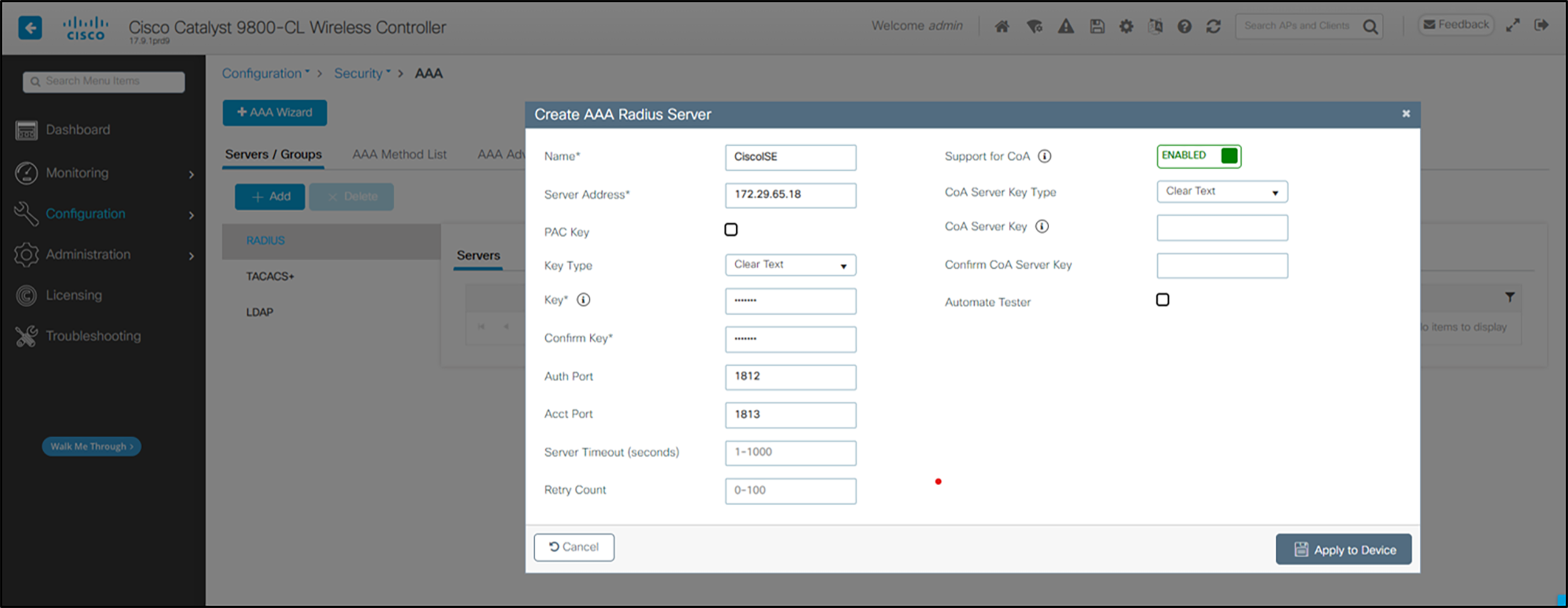
8. Click Update and Apply to Device.
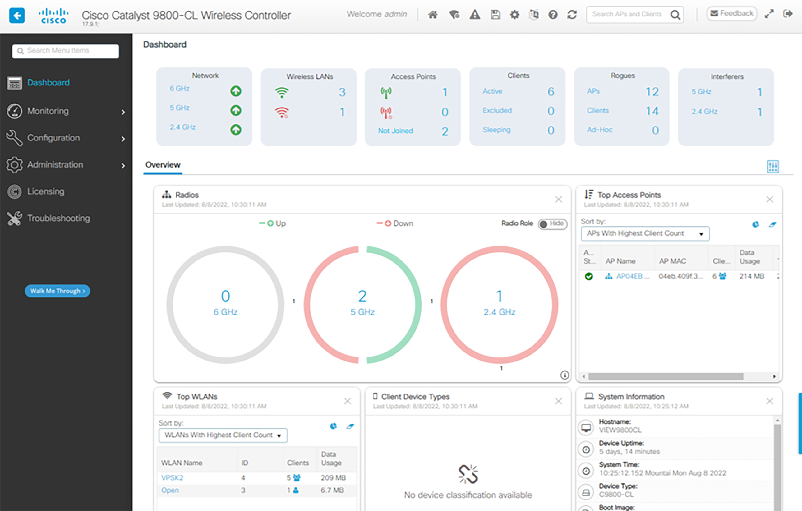
1. Power on and connect the APs to the network. Wait a few minutes for the APs to find the controller.
2. Verify that the APs are associated to the WLC.
3. From the Dashboard, under Access Points, click on the number by the green wireless icon to view the list of connected AP’s, the red wireless icon to view AP’s connected but not active, or by Not Joined to view AP’s that have been prevented from joining or may be in the process of joining.
Configuration for use with 2.4-GHz radio
1. From the menu select Configuration and under Wireless click Access Points.
2. In the navigation pane, under All Access Points click 2.4 GHz Radios. All the APs that are connected should be listed, showing their Operational Status for that radio band.
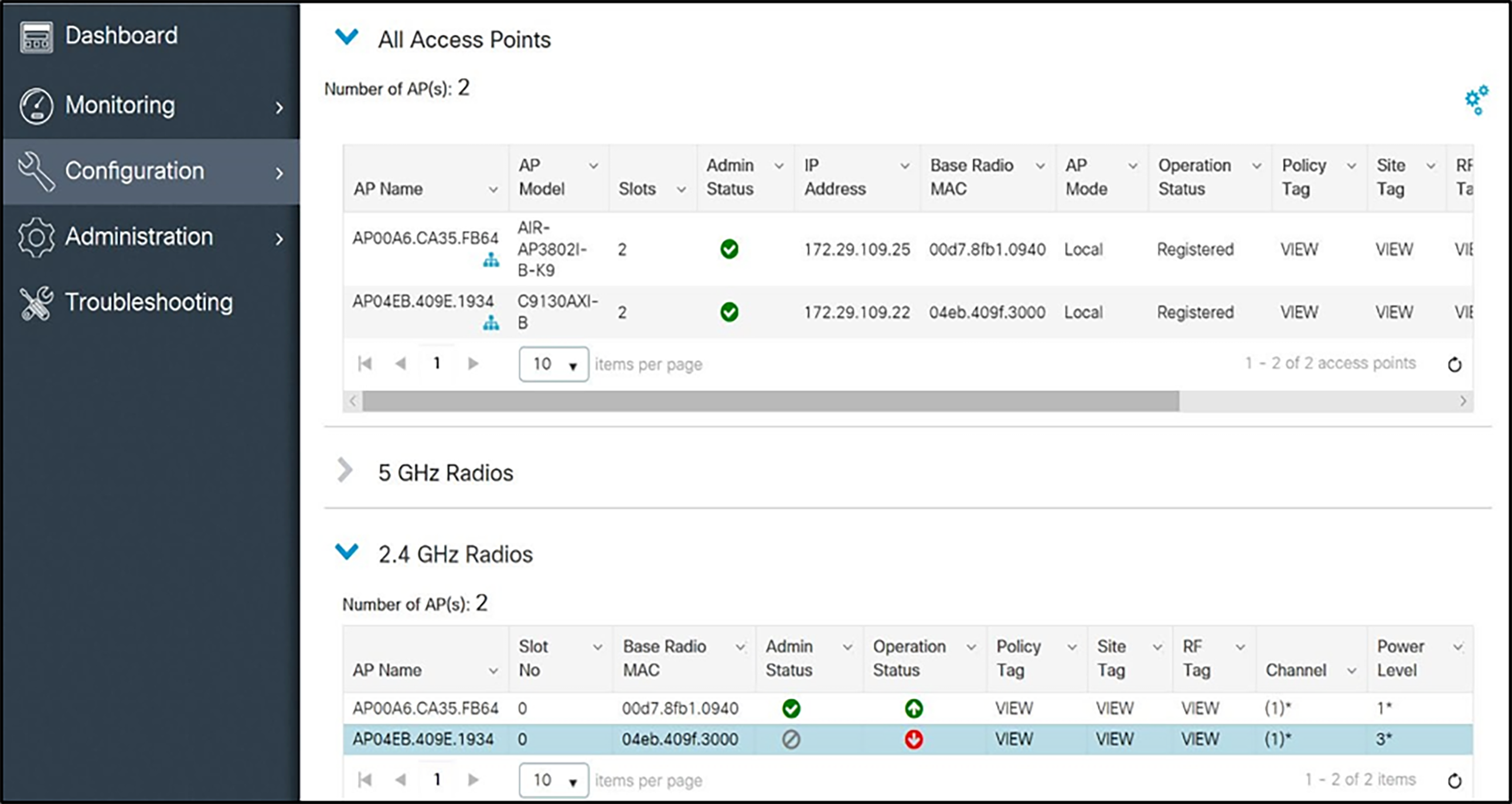
3. Click the AP for the access point you wish to change. Set the parameters for that AP:
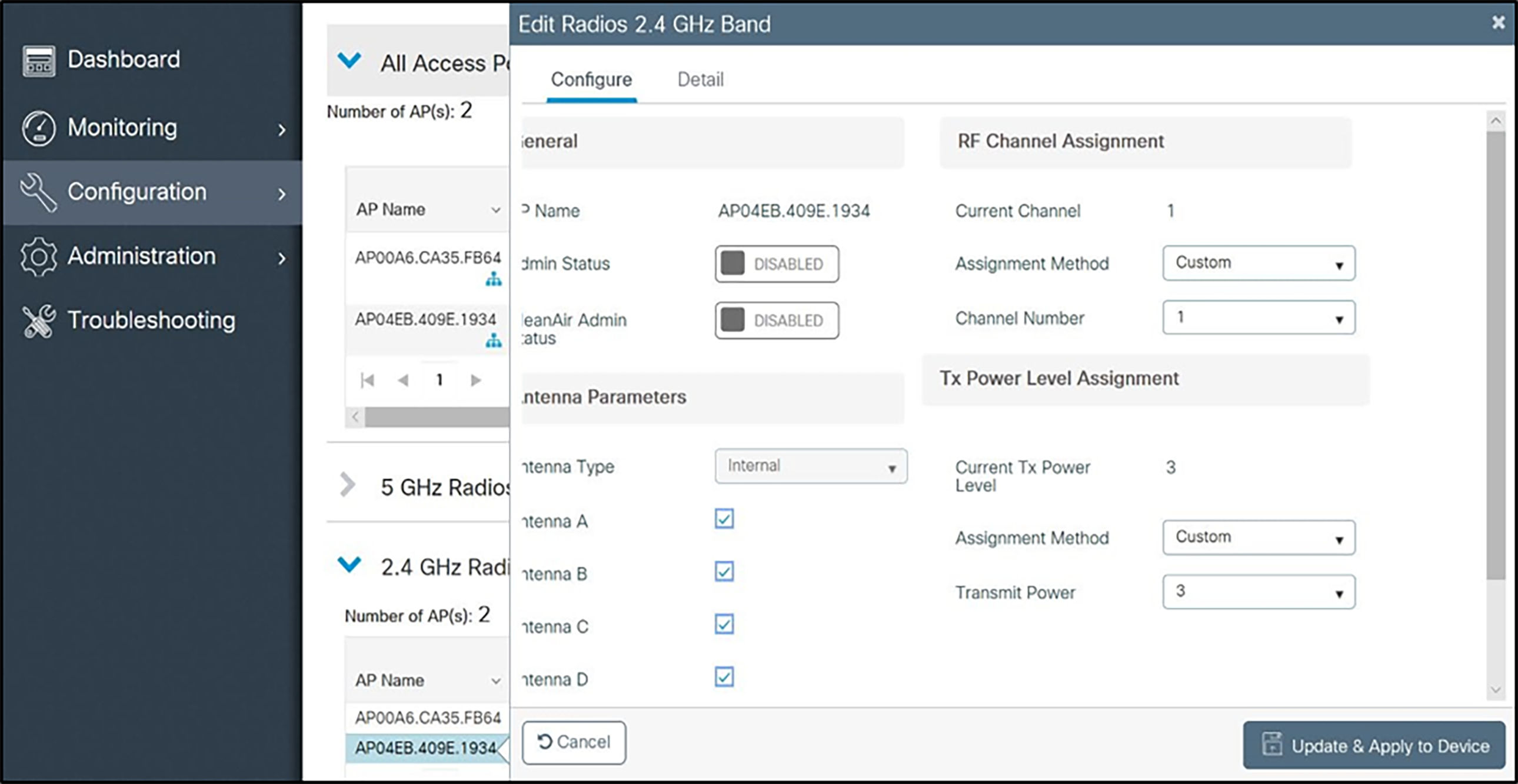
d Set Admin Status to Enable.
e Configure any other settings that might be relevant to your deployment as needed.
f Click the Update and Apply to Device button to save all changes.
Network settings
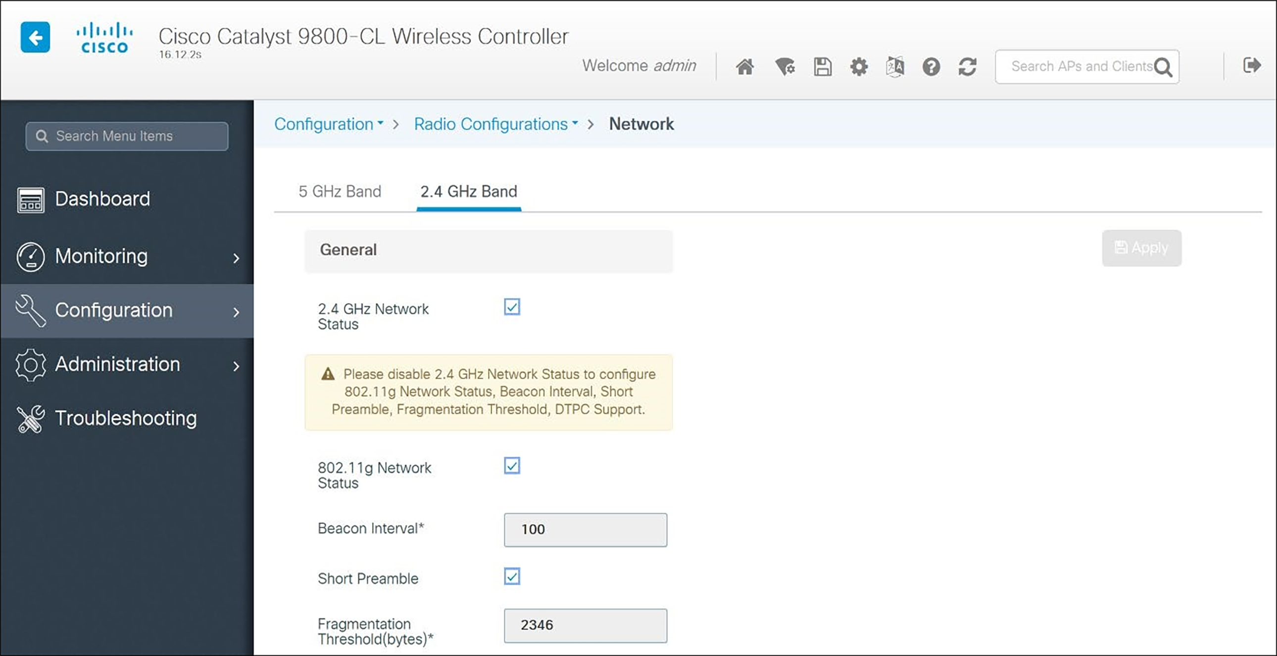
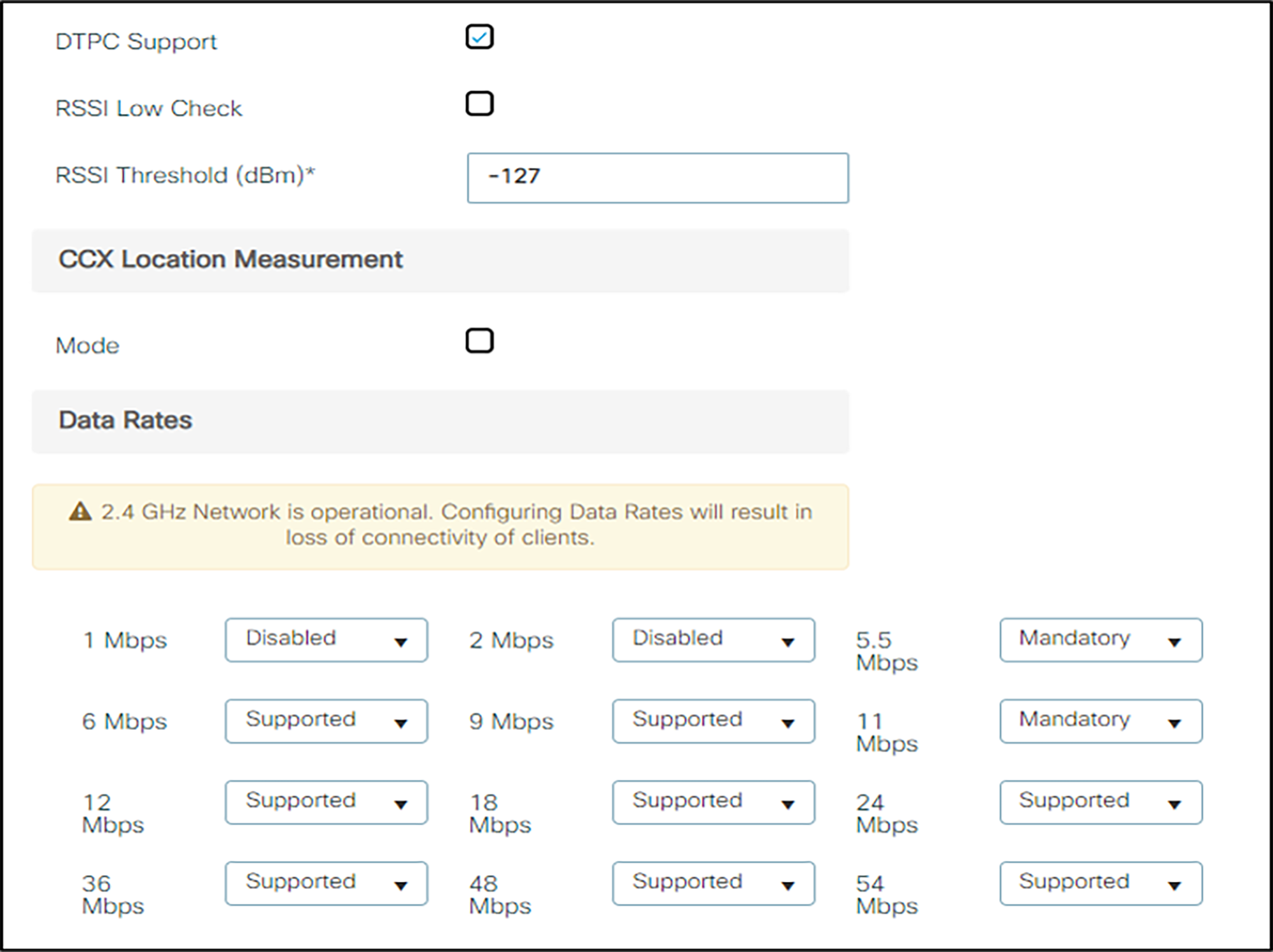
In the navigation pane under Configuration, then Radio Configurations, click Network, then the 2.4 GHz Band tab. Set network parameters as follows:
1. Uncheck 2.4GHz Network Status. The radio will be re-enabled after setting radio parameters.
2. Use the default Fragmentation Threshold (2346 bytes).
3. Set the Beacon Interval to 100.
4. Check Short Preamble.
5. DTPC is a Cisco proprietary method of matching phone power to AP power. In the 84-series handsets, it is selected by choosing the Auto power setting in handset configuration. Versity is in Auto mode by default. Check DTPC.
6. Set the 1 Mbps and 2 Mbps settings to Disabled.
7. Click the Apply button to save the settings.
RRM parameters
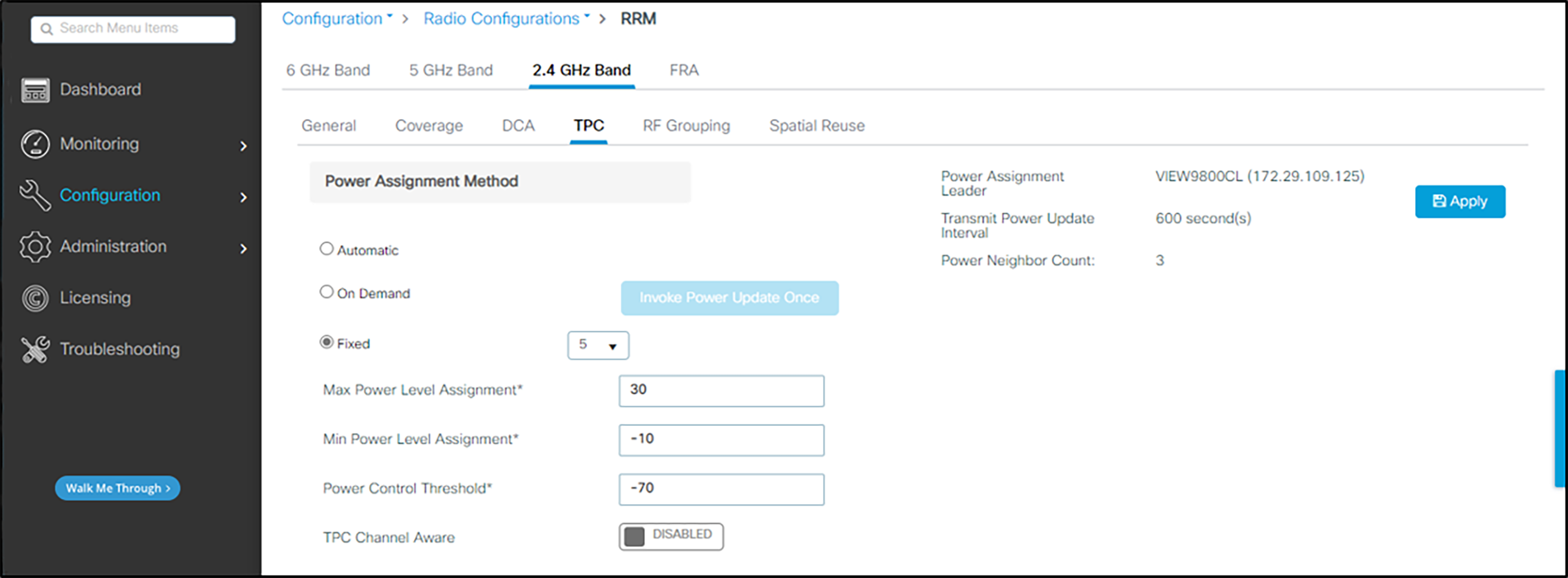
In the navigation pane under Configuration, under Radio configurations click RRM. Set RRM parameters for 2.4GHz band as follows:
1. Click TPC. Set the Power Assignment Method to Fixed. (The On Demand/Invoke Power Update Once setting may be deployed occasionally to allow the Cisco network to self-configure at a time of low usage). Note that the individual AP assignments shown above override the Fixed power level set here. Frequent automatic power changes will cause poor audio quality.
2. As recommended by Cisco for the 2.4 GHz Band, leave the TPC Channel Aware setting DISABLED.
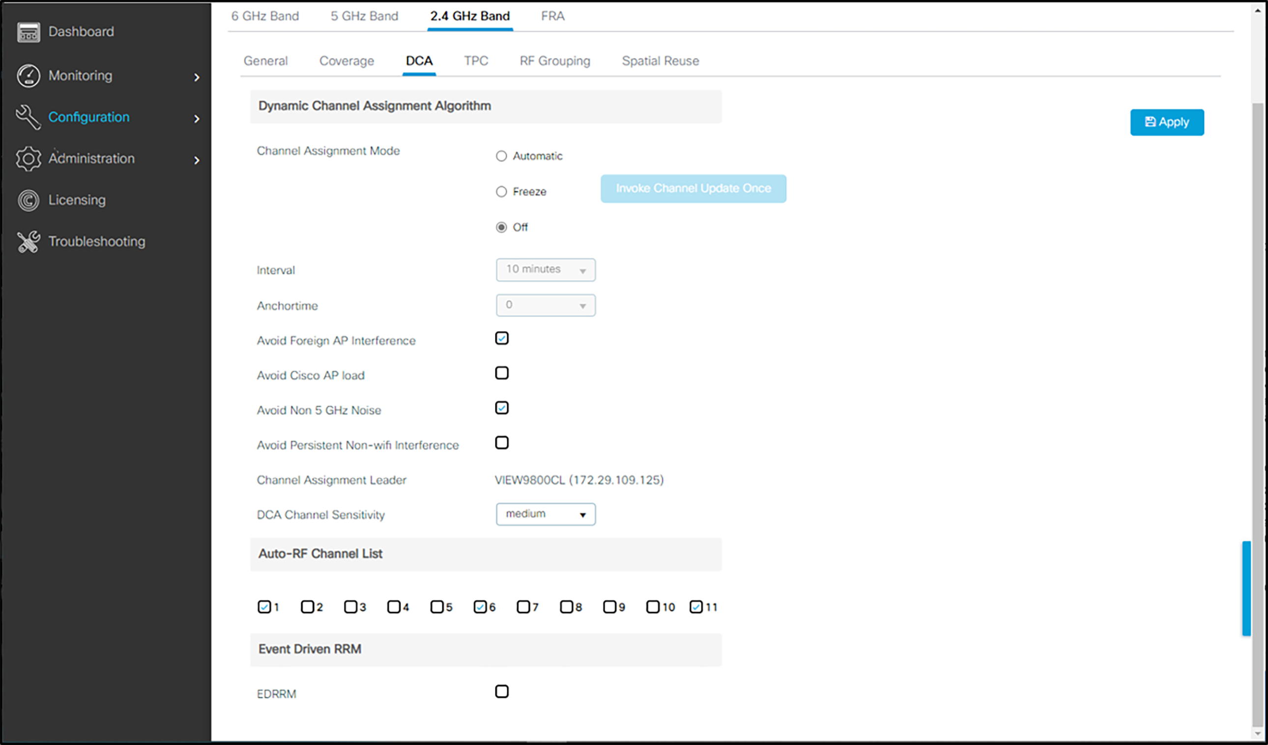
3. Click DCA. Set the Dynamic Channel Assignment Algorithm to Off. (The Freeze/Invoke Channel Update Once setting may be deployed occasionally to allow the Cisco network to self-configure at a time of low usage.) Leave the default settings of 1, 6, and 11.
Media (voice/video)
For 84-Series handsets Admission Control (ACM) must be enabled on both the Voice and Video AC only when the handset is configured for Admission Control Mandatory. Optional is the recommended setting at this time, as it will allow flexibility in the network.
Versity does not implement ACM. Versity smartphones are compatible with ACM Enabled. They will default to a lower class for calls, which may hurt call quality if there are many devices using ACM.
To enable Admission Control (ACM)
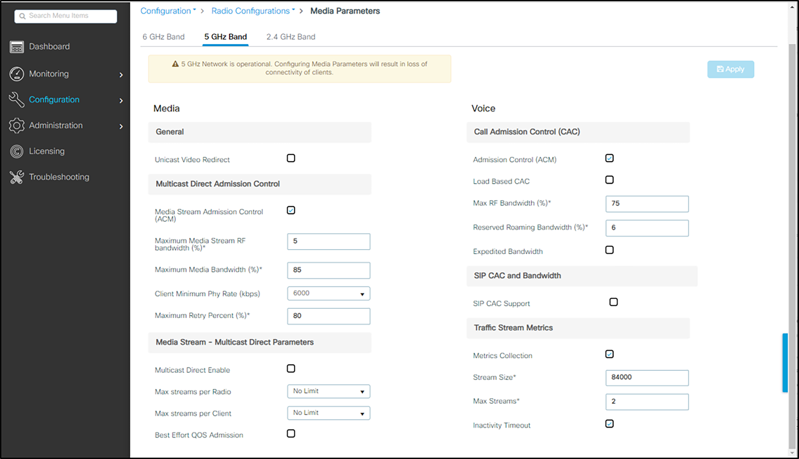
1. Navigate to Configuration>Radio Configurations>Media Parameters.
2. Select the 5 GHz Band tab.
3. Under Media:
g Ensure that Unicast Video Redirect, Multicast Direct Enable, and Best Effort QOS Admission are unchecked.
h To enable admission control for the SIP call control packets, check Media Stream Admission Control (ACM)
4. Under Voice:
i Check Admission Control (ACM)
j Uncheck Load Based CAC.
k Ensure that the Reserved Roaming Bandwidth (%) is set to 6%.
l Ensure that SIP CAC Support is unchecked.
Admin tip: Use the Static CAC method
It is very important to choose the Static CAC method to avoid limiting calls when there is heavy background traffic.
Admin tip: Disable WLAN before changing Admission Control settings
Any WLAN using the network must be disabled before changing the Admission Control settings.
5. Click Apply to save the settings.
Configuring 802.11n/802.11ac for 5 GHz
1. In the navigation pane, select Configuration, and under Radio Configuration select High Throughput (802.11n/ac). Check the radio box to enable 11n and 11ac mode and allow all data rates to be supported.
2. Click the Apply button to save the settings.
802.11a/n APs

802.11 a/n/ac/ax APs
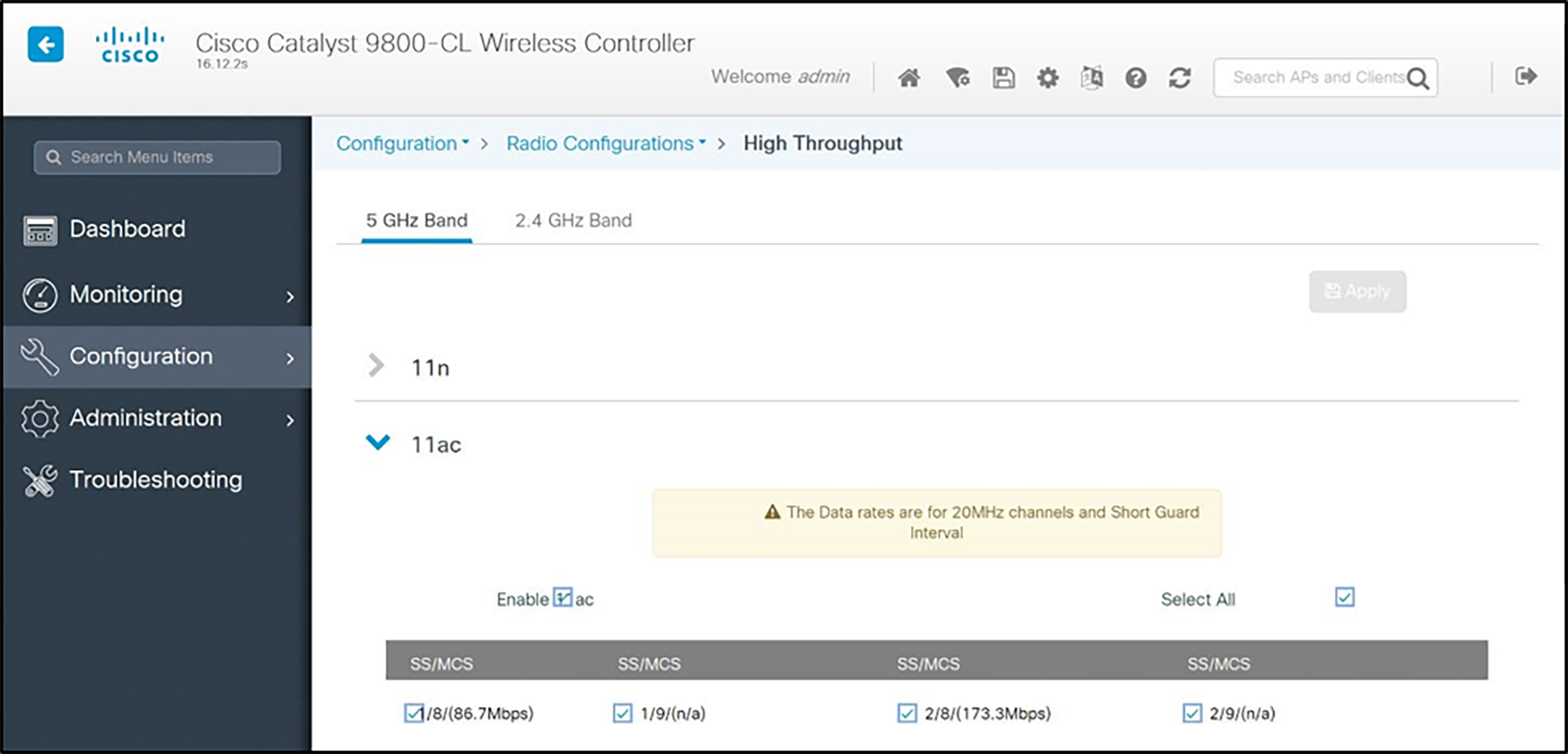
Admin tip: 802.11ac
Spectralink has been tested with 802.11ac clients in the network. It is not interoperable with the snap-in module for the Aironet 3600 Series APs, even in other radio modes.
Specific AP Power/Channel Configuration
1. From the main menu, click Configuration.
2. In the navigation pane, under Wireless click Access Points, then select all desired radio bands.
3. Double click an AP from the drop-down list for the access point you wish to change. Set the parameters for that AP:
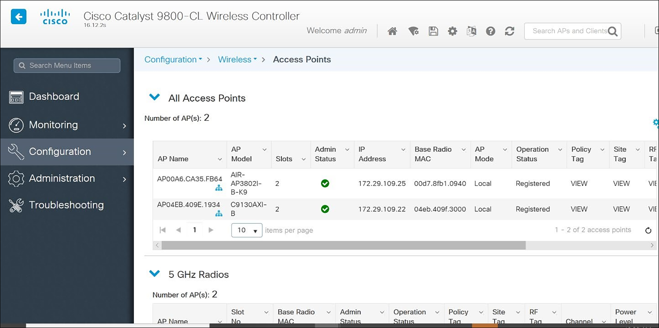
Settings: Power and channel settings
Global settings for RF Channel Assignment and Tx Power Level Assignment were not tested. For Custom Tx Power and RF Channel settings please consult your facility’s RF site survey — optimized for wireless voice traffic — to determine correct power and channel settings for each AP using non-overlapping channels.
4. Configure any other settings that might be relevant to your deployment as needed.
5. Click the Update and Apply button to save all changes.
Voice and data must be on separate SSIDs to prioritize voice traffic. The voice SSID must be set to Platinum for Quality of Service and the data SSID must be set to Silver for Quality of Service.
1. Create a new SSID and give it a name:
a From the main menu, click Configuration, select WLANs under Tags and Profiles.
b In the WLANs screen, select +Add.
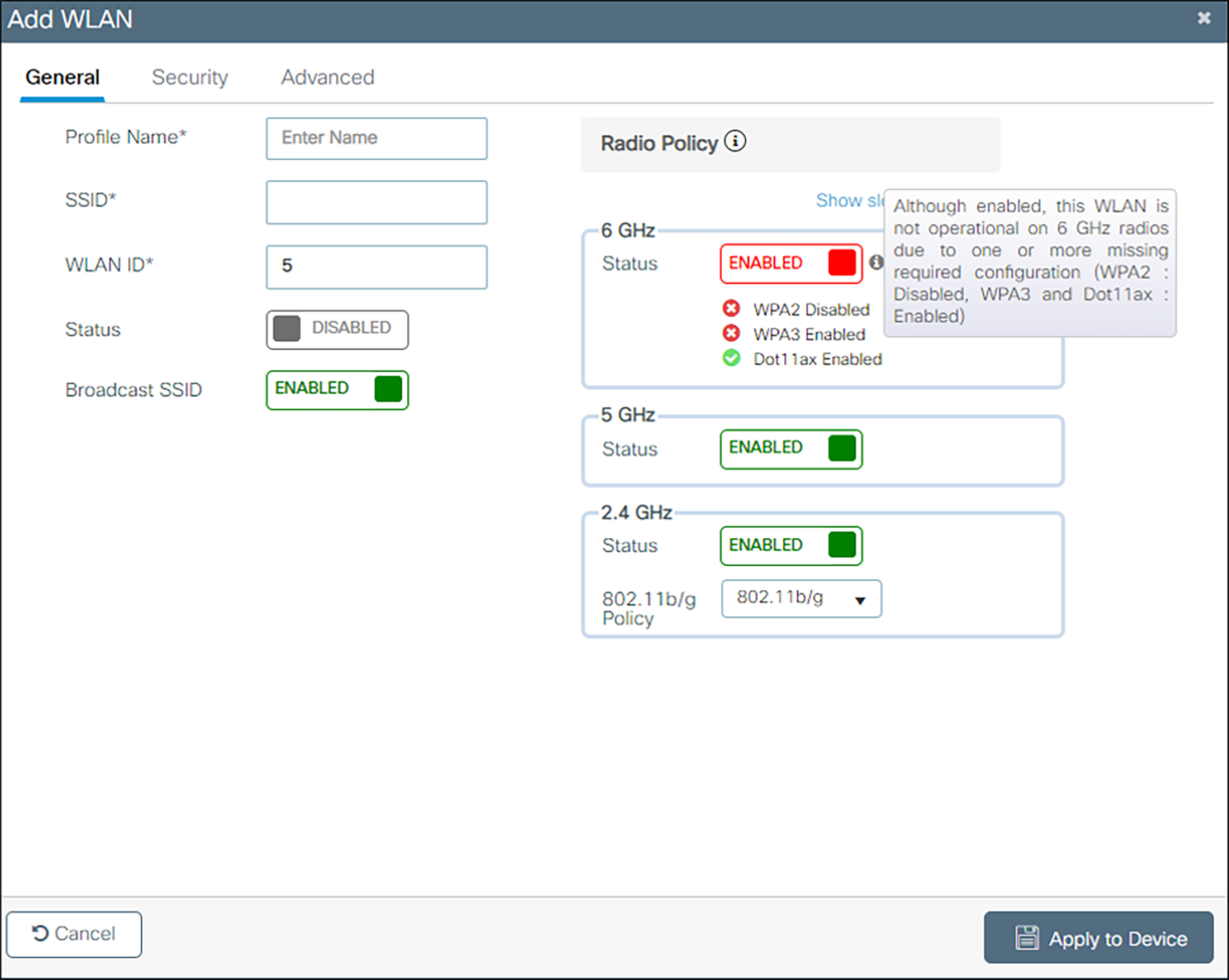
c Enter the Profile Name and SSID.
d Click the Update and Apply to Device button.
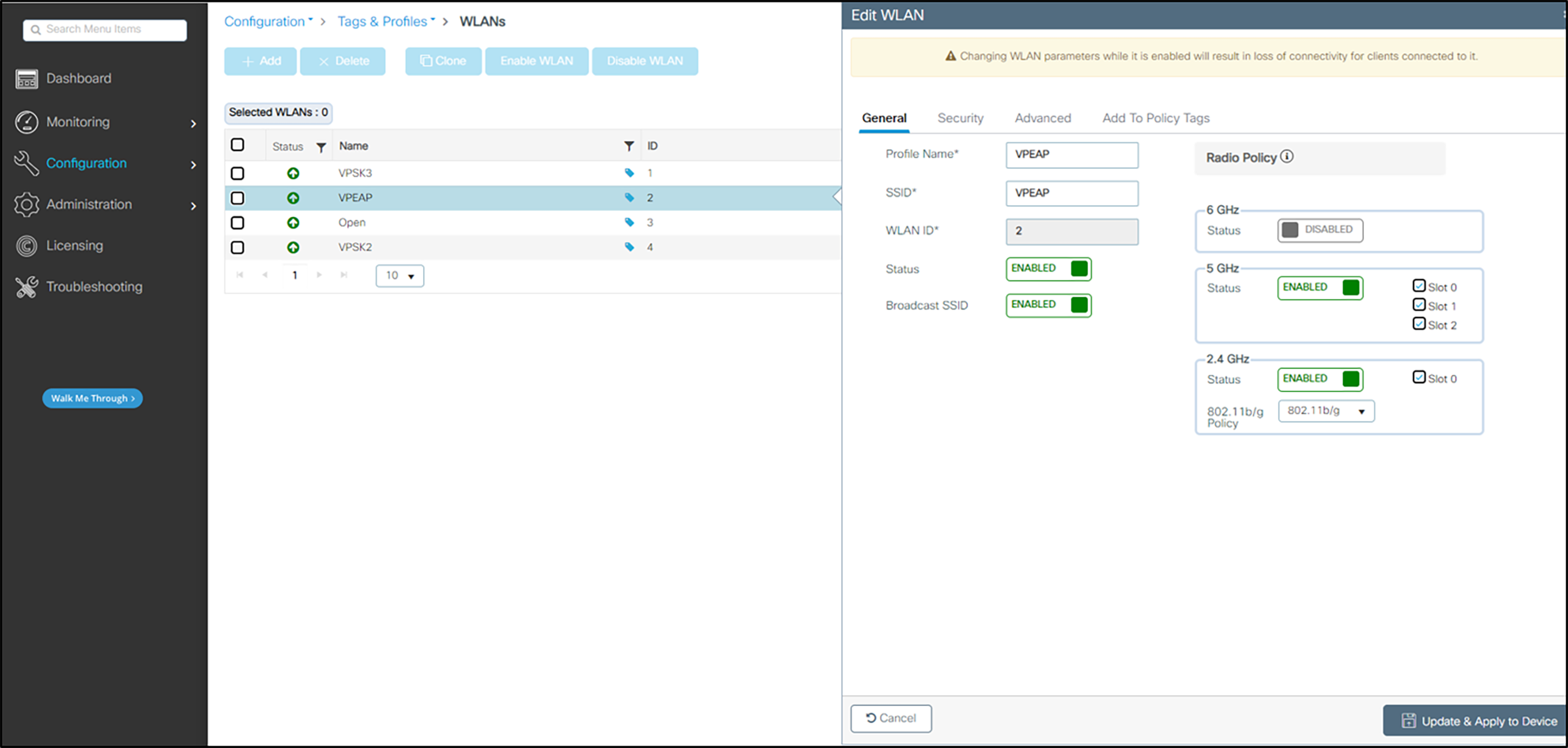
2. Define the General settings:
a Select the Profile Name for the voice SSID.
b Under the General tab, verify the Radio Policy corresponds to the Spectralink Wireless Telephone configuration.
c For Status, select the Enabled check box.
d Check Broadcast SSID to make the network public. Uncheck it to make it a hidden network.
Admin Tip: 84-, 92-, 95-, and 96-series phones do not support 6 GHz operation.
The 84-, 92-, 95-, and 96-series phones do not support WPA3 or 6 GHz operation. This means that the 6 GHz radio should always be disabled for WLAN profiles which support those phone models.
3. Define Security Settings:
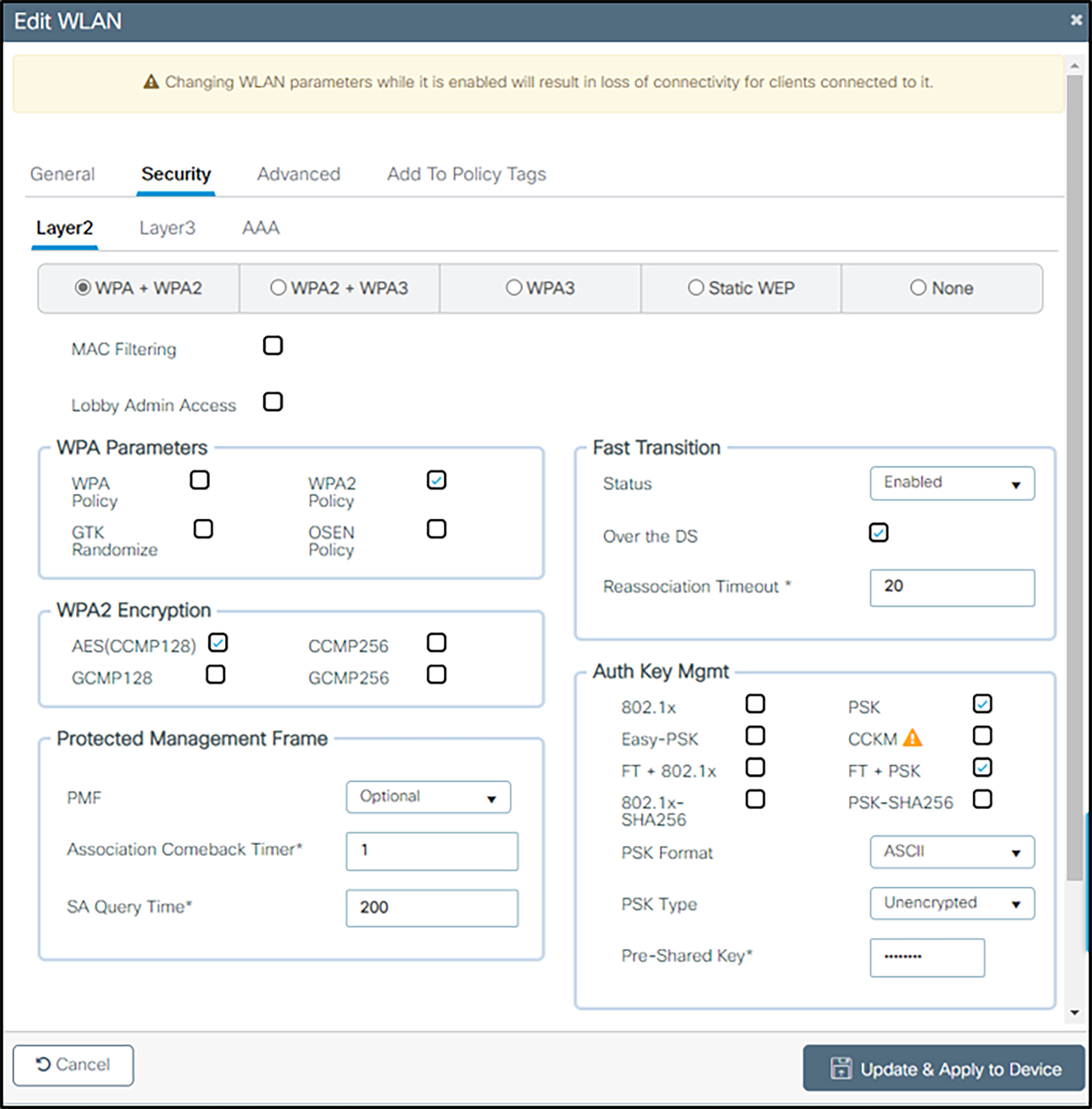
For WPA2-PSK:
From the Layer 2 tab:
a Check WPA+WPA2.
b Check AES (CCMP128) under WPA2 Encryption.
c Under WPA Parameters check WPA2 Policy and ensure that GTK Randomize is unchecked.
d Under Protected Management Frame, set PMF to Optional. (The 92-, 95-, and 96-series phones support protected management frames and the 84-series phones do not.)
e Under Fast Transition, select Enabled and leave Reassociation Timeout at the default. Both Over the DS and Over the Air FT Roaming are supported by the 92-, 95-, and 96-series phones.
Admin Tip: 84-series phones do not support FT Roaming.
The 84-series phones support OKC and CCKM fast roaming only. CCKM is a Cisco-proprietary method that is scheduled to be removed.
f Under Auth Key Mgmt, select PSK and either FT+PSK or CCKM, whichever is appropriate for the type of handsets deployed. Note that multiple methods can be indicated, The handsets will indicate the type that they need, PSK Format as ASCII or Hex depending on what the phones are using, and the Pre-shared Key (called a passphrase in the 84-series menus and a password on Android phones).
g Ensure that nothing is checked as Enabled on the AAA Servers tab.
For WPA2-Enterprise (802.1X):
From the Layer 2 tab:
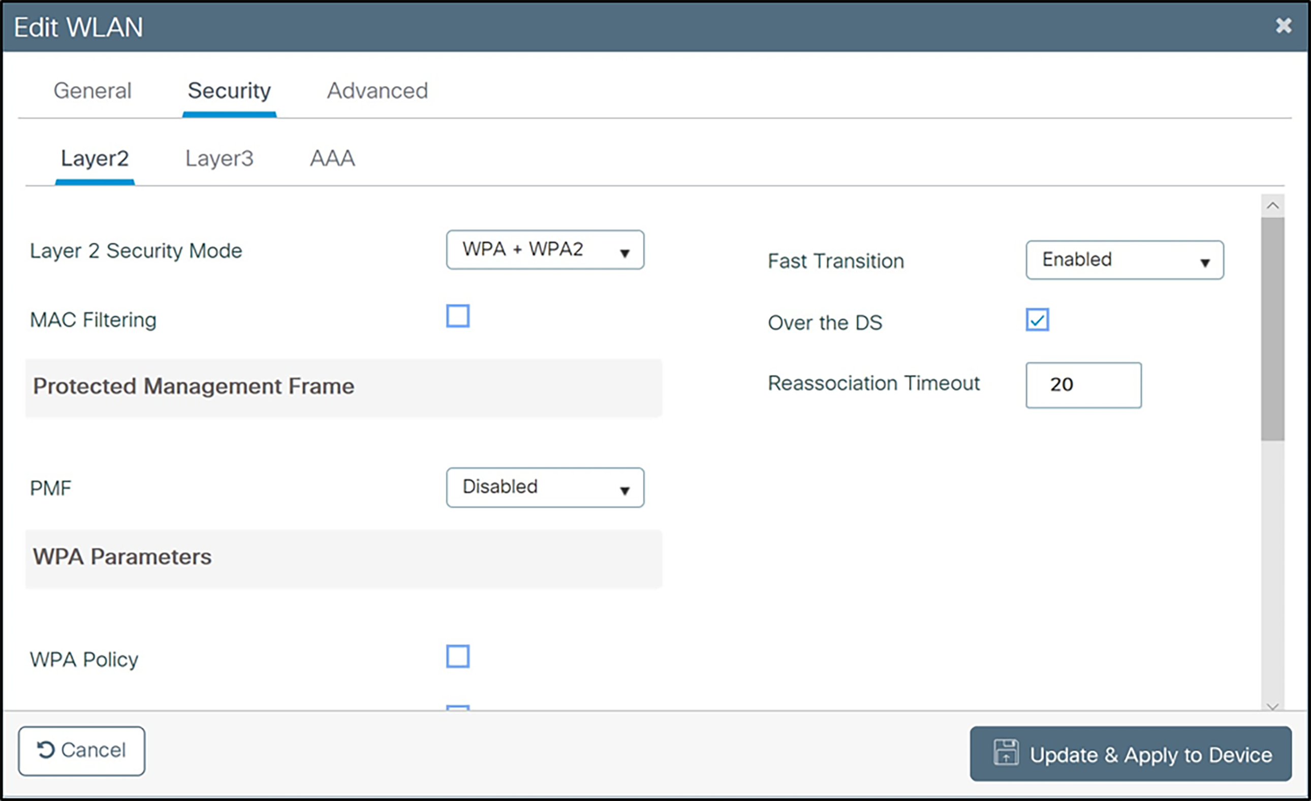
h Check WPA+WPA2.
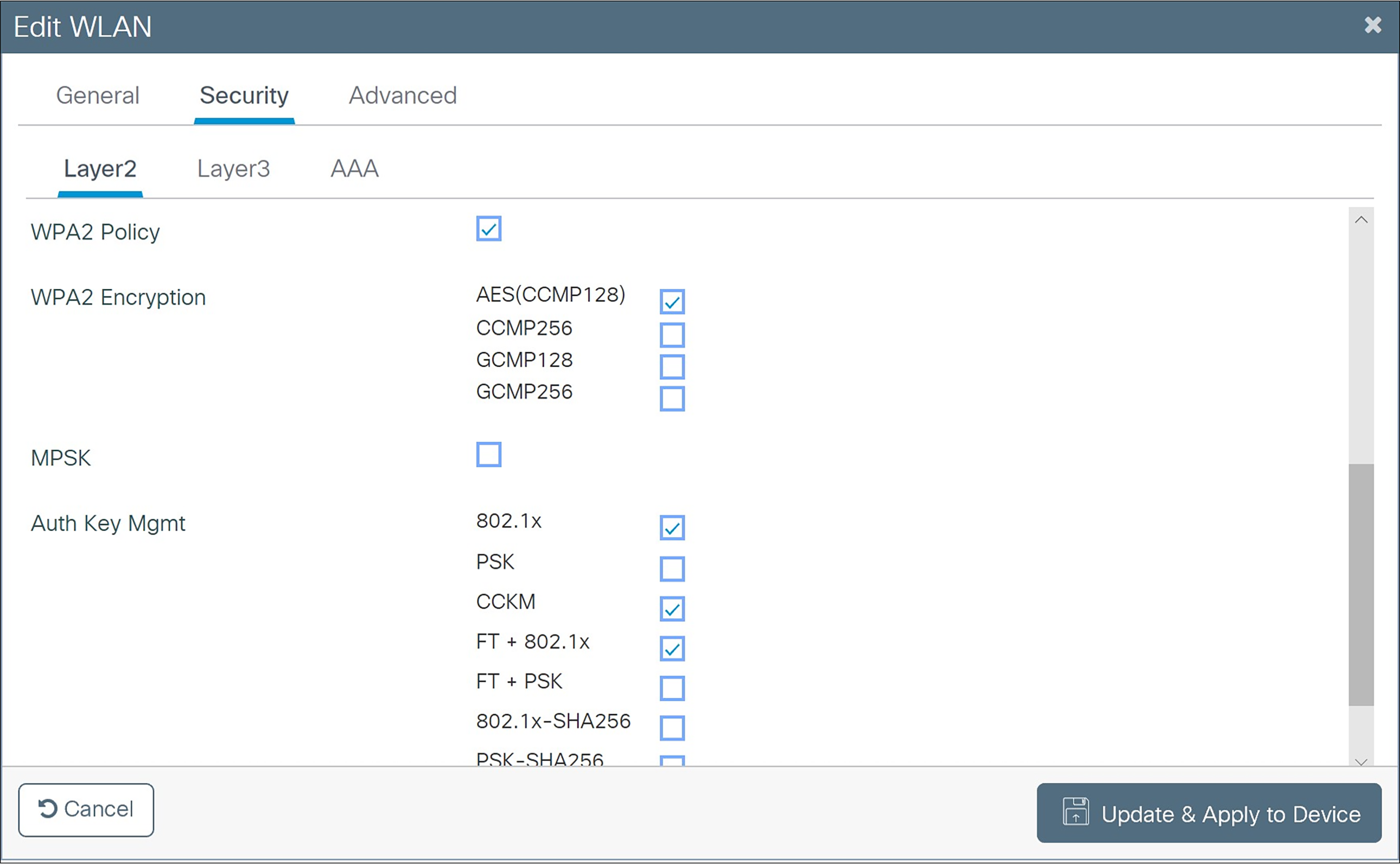
i Check AES (CCMP128) under WPA2 Encryption.
j Under WPA Parameters check WPA2 Policy and ensure that GTK Randomize is unchecked.
k Under Protected Management Frame, set PMF to Optional. (The 92-, 95-, and 96-series phones support protected management frames and the 84-series phones do not)
l Under Fast Transition, select Enabled and leave Reassociation Timeout at the default. Both Over the DS and Over the Air FT Roaming are supported by the 92-, 95-, and 96-series phones.
m Under Auth Key Mgmt, select 802.1X, FT+802.1X, and CCKM.
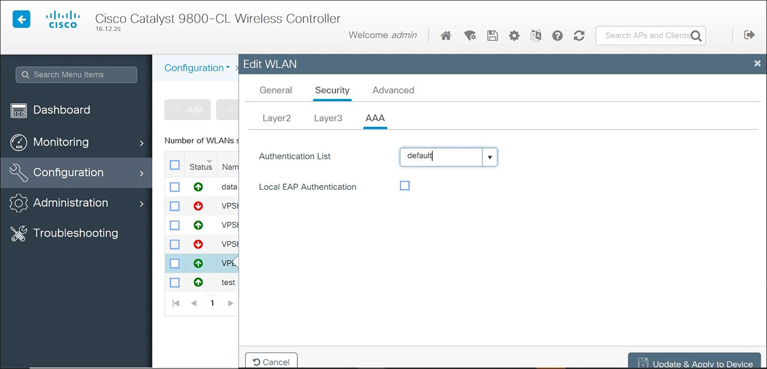
4. On the AAA tab, choose the Authentication List from the dropdown.
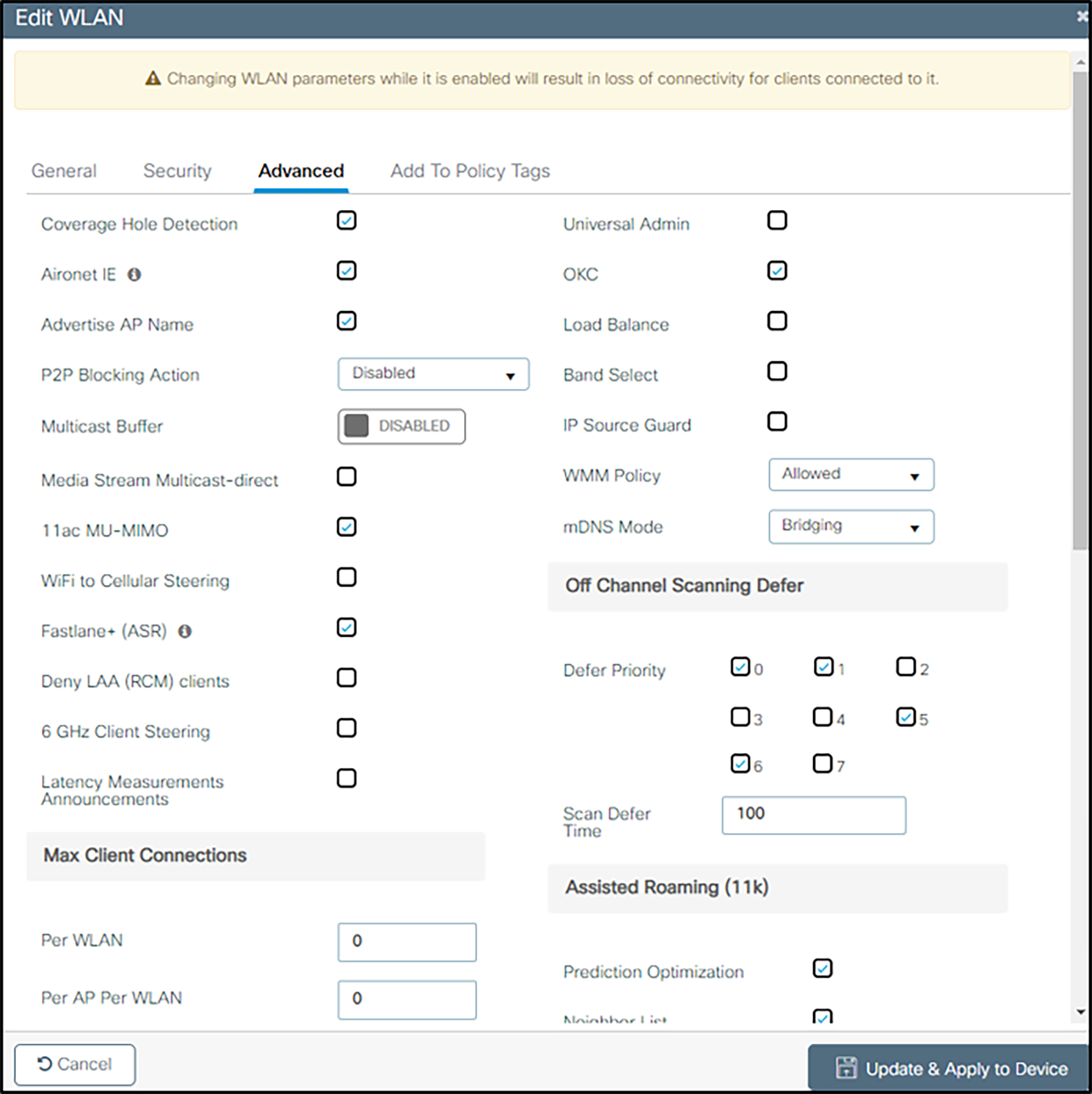
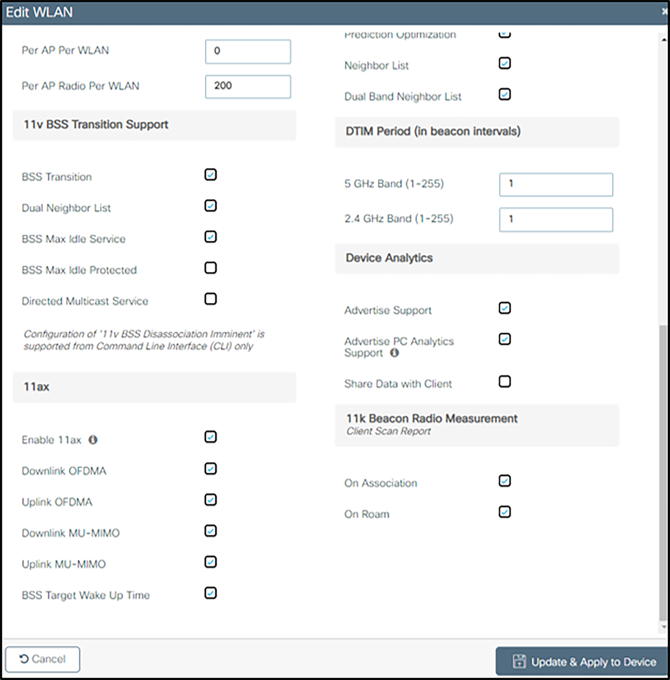
5. (For all security types) Under the Advanced tab:
a May be set as desired by site administration considerations:
In sections without headings:
● Coverage Hole Detection
● Aironet IE
● Advertise AP Name
● P2P Blocking Action
● 11ac MU-Mimo
● Fastlane+ (ASR)
● Deny LAA (RCM) clients
● Latency Measurement Announcements
● Universal Admin
● IP Source Guard
● mDNS Mode
Sections with headings:
● Max Client Connections (all settings as desired)
● 11ax (will not be used by 84-series or Versity phones – set as desired)
● Device Analytics (all settings as desired)
● 11k Beacon Radio Measurement (all settings as desired)
b Settings with importance to handsets
In sections without headings:
● If PTT is in use, ensure that Multicast Buffer is DISABLED and Media Stream Multicast-direct is unchecked
● Ensure that WiFi to Cellular Steering is unchecked
● Ensure that 6 GHz Client Steering is unchecked
● Ensure that OKC is checked
● Ensure that Load Balance is unchecked
● Ensure that Band Select is unchecked
● Ensure that WMM Policy is set to Allowed
In the 11v BSS Transition Support section:
● Ensure that BSS Transition is set
● Check Dual Neighbor List
● Ensure BSS Max Idle Service is checked
● Ensure BSS Max Idle Protected is unchecked
● If PTT is in use, uncheck Directed Multicast Service
In the Off Channel Scanning Defer section:
● Check Defer Priority for the 0, 5, and 6 priority classes (prevents contention between off-channel scanning and PTT, voice calls, or call server communication)
In the Assisted Roaming (11k) section:
● Check Prediction Optimization
● Ensure that Neighbor List is checked
● Check Dual Band Neighbor List
In the DTIM Period (in beacon intervals) section, ensure all band settings are set to 1
Admin Tip: 84-, 92-, 95-, and 96-series phones do not support 6 GHz operation or 11ax.
SSIDs which support the phones should not direct them to the 6 GHz band.
6. Click the Apply button to save all changes.
Admin Tip: Do not enable Disassociation Imminent from the cli.
Spectralink phones are not compatible with the use of the Disassociation Imminent message used for the channel switch announcement feature.
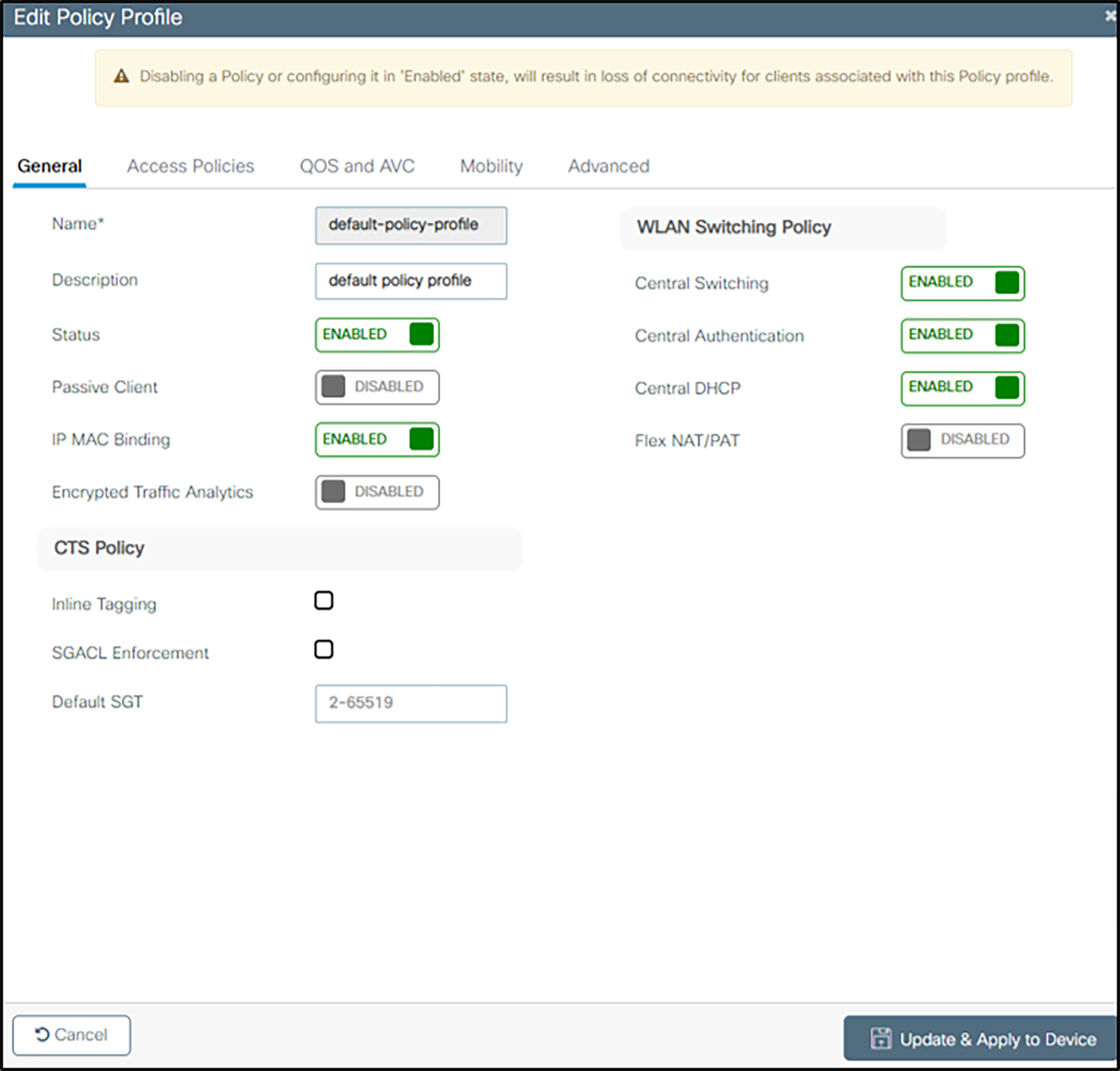
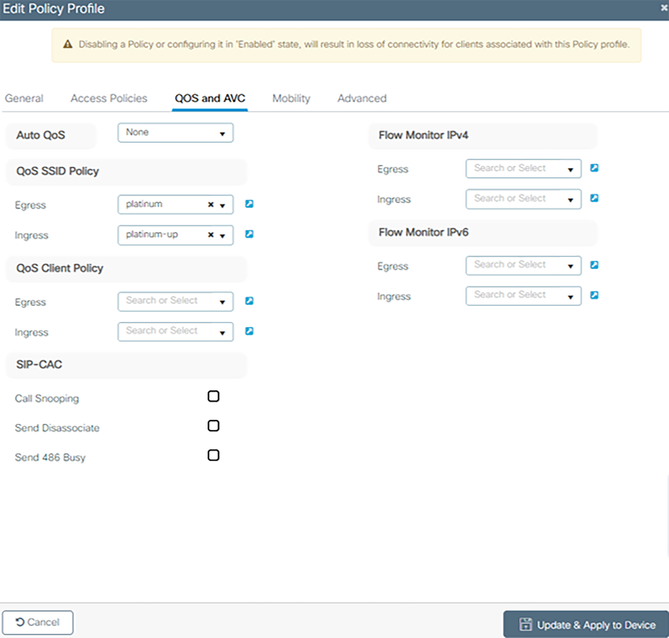
The WLAN QoS policy profiles must be setup once WLAN profiles i.e. once WLANs have been created. Navigate to Configuration, select Policy under Tags and Profiles and click +Add.
1. Under General Enter Name and Description and toggle Status to Enabled.
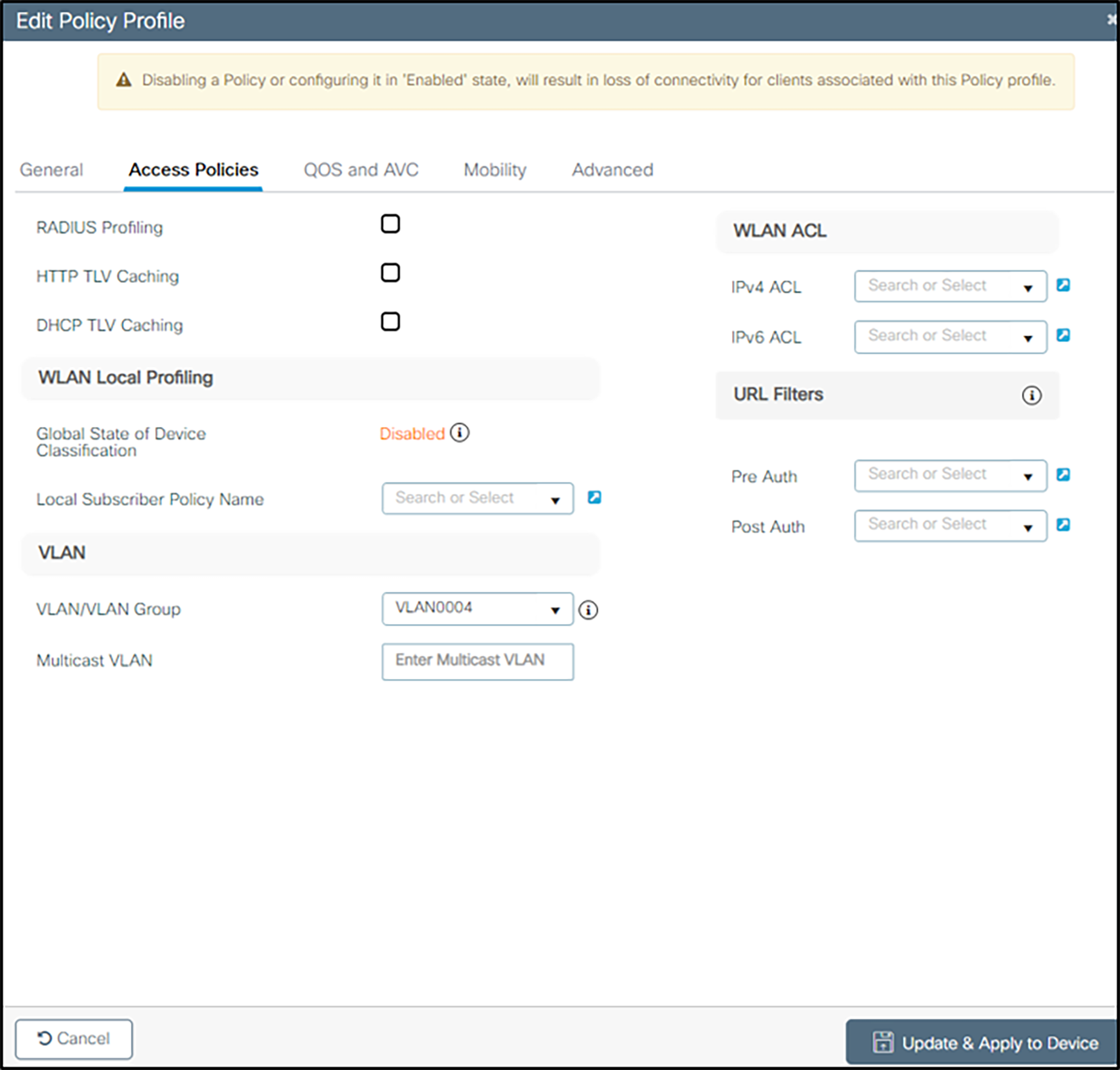
2. Under Access Policies,
a Enter the VLAN/VLAN Group
b Within the WLAN ACL section, expand and enter settings as necessary for local admin policy to permit/deny services as necessary.
3. Under QOS and AVC, select platinum for Egress and platinum-up for Ingress for QOS SSID policy. This is the required setting for voice traffic.
4. Under the Advanced tab, set 86400 as Session Timeout and uncheck Client Exclusion Timeout
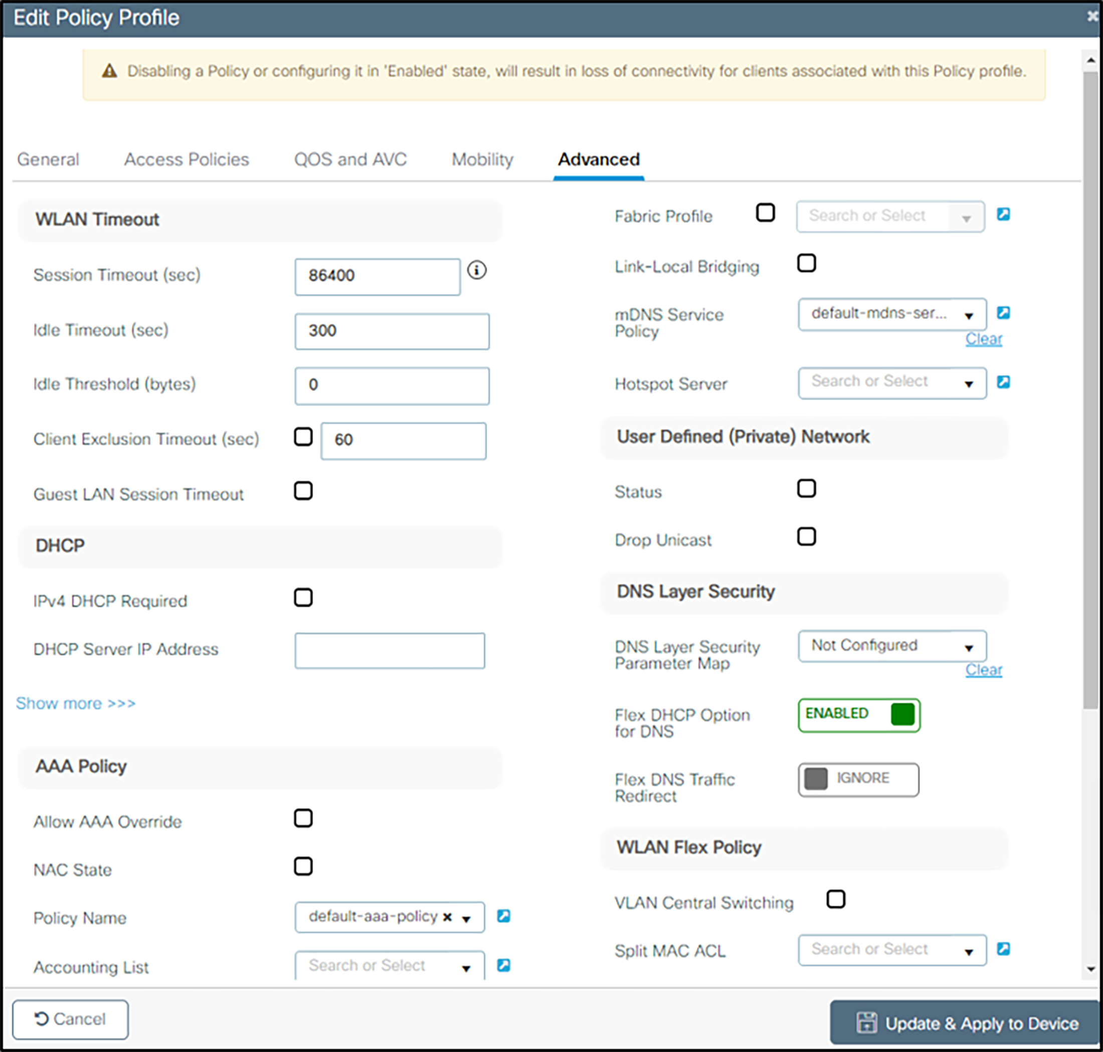
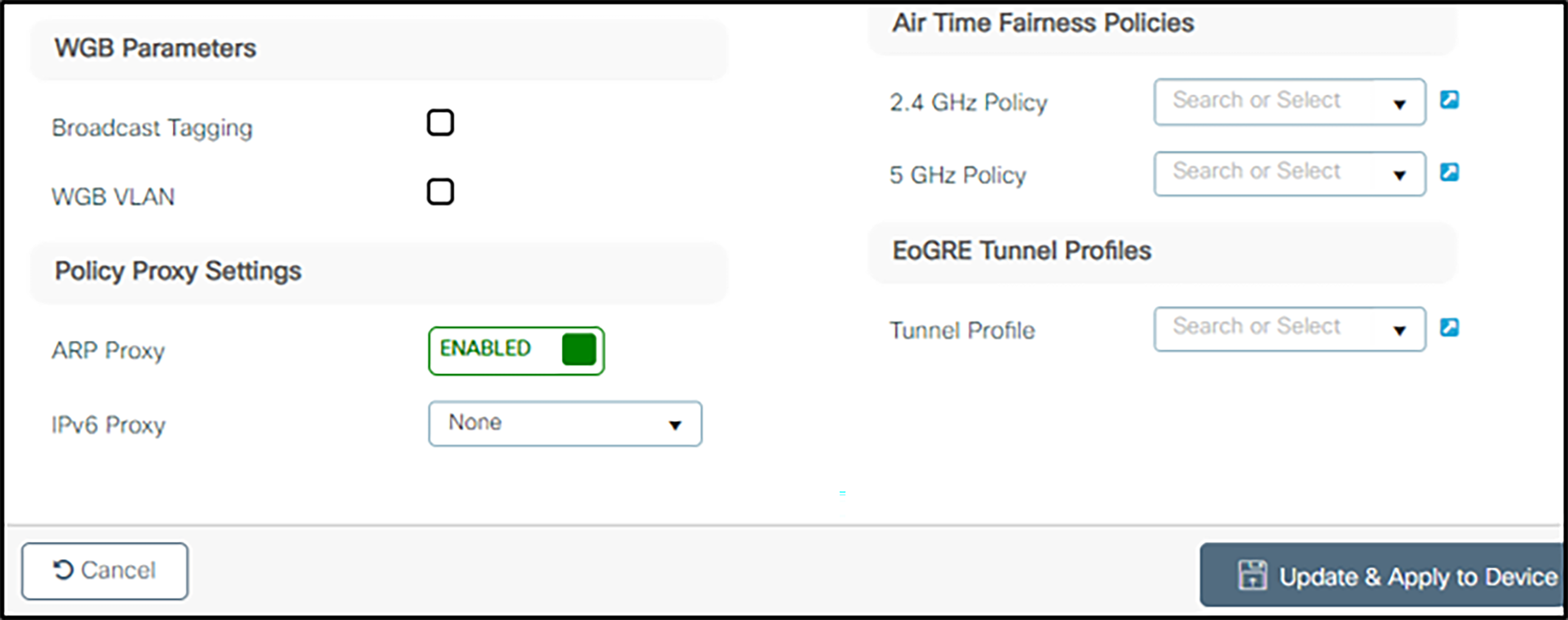
5. Ensure that ARP Proxy is ENABLED.
6. Make any other changes according to local network.
7. Click on Update and Apply to Device.
Setting up the EDCA parameters profile
The Enhanced Distributed Channel Access (EDCA) parameters must be set to the WMM settings after the WLAN network QoS has been set.
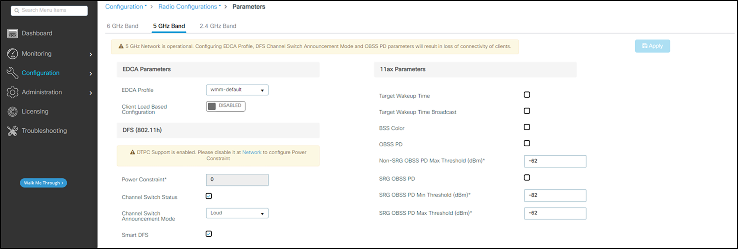
Configuration for 5 GHz
1. In the navigation pane under Configuration, select Parameters under Radio Configurations.
2. Under EDCA Parameters ensure that wmm-default is selected from the drop-down list for EDCA Profile.
3. To use DFS channels, ensure that Channel Switch Status is checked, Channel Switch Announcement Mode is Loud and Smart DFS is checked.
4. If desired, a power constraint can be entered to use TPC mode cell size matching control. The Spectralink handsets do have both DTPC and TPC capability. The 84-series phones will use these values if their sub-band power is set in the Auto mode. See the 84-series Administration Guide for details. The Versity handsets are always set up to use DTPC or TPC if either is enabled. If neither mode is enabled, Versity handsets will set themselves as close to the maximum for the regulatory domain values contained in their factory settings as is possible for the hardware.
5. Click Apply.
Configuration for 2.4 GHz
1. In the navigation pane under Configuration, select Parameters under Radio Configurations.
2. Under EDCA Parameters ensure that wmm-default is selected from the drop-down list for EDCA Profile.
