Cilium and ACI: Modular design for Network Visibility and Load Balancing White Paper
Available Languages
Bias-Free Language
The documentation set for this product strives to use bias-free language. For the purposes of this documentation set, bias-free is defined as language that does not imply discrimination based on age, disability, gender, racial identity, ethnic identity, sexual orientation, socioeconomic status, and intersectionality. Exceptions may be present in the documentation due to language that is hardcoded in the user interfaces of the product software, language used based on RFP documentation, or language that is used by a referenced third-party product. Learn more about how Cisco is using Inclusive Language.
Kubernetes has become the de facto standard for container orchestration in today’s cloud-native ecosystem, providing a robust framework for deploying, scaling, and managing containerized applications. As enterprises increasingly adopt Kubernetes, they are often faced with the challenge of ensuring seamless network connectivity and service discovery across diverse and dynamic environments.
Traditionally, implementing BGP peering to all the nodes in a Kubernetes cluster has been the go-to strategy to provide security and visibility into the workload running on the cluster as well as handling external services routing and load-balancing requirements.[1]
BGP peering enables Kubernetes nodes to directly exchange routing information, promoting efficient network traffic flow, and reducing latency.
However, as clusters grow in size and complexity, the practice of establishing BGP sessions with nodes becomes less practical. The operational overhead, configuration complexity, and scaling limitations imposed by the L3Outs can impede the agility and flexibility that Kubernetes aims to offer.
Until recently, organizations had few choices:
● Grapple with the complexities of BGP peering; or
● Deploy Kubernetes clusters with network overlays and external load balancers; or
● Deploy the Cisco ACI® CNI Plug-in to achieve a seamless network layer between the Kubernetes Pod network and the fabric. This last option is, however, not always possible.
This white paper proposes a hybrid design where only a subset of nodes participate in BGP peering, significantly reducing the design and operational complexity as well as addressing all BGP scalability issues.
At present, this design does not necessitate the use of supplementary components from Cisco or other third-party vendors to meet its objectives. While there is the potential for users or the open-source community to create tools that automate the Cisco ACI configuration, such developments are optional and beyond the scope of this design document.
This white paper will thoroughly examine the technical underpinnings, implementation considerations, and operational benefits of this approach. It will guide readers through the process of implementing this hybrid model, ensuring that network reliability, performance, and security are not only preserved but significantly enhanced.
The design goals for our Kubernetes networking solution focus on addressing the critical challenges faced by administrators when managing traffic flow and ensuring secure connectivity within and outside the Kubernetes cluster. Our approach is to implement a robust and scalable load-balancing strategy coupled with a secure networking model that bridges the gap between containerized applications and external non-containerized systems.
1. Efficient load balancing:
a. Design and implement a load-balancing mechanism that effectively distributes external client traffic to services within the Kubernetes cluster
b. Utilize a subset of cluster nodes to perform BGP peering, enabling Layer- 3/Layer-4 Equal-Cost Multi-Path (ECMP)–based load balancing
c. Minimize design complexity while maximizing traffic optimization, achieving a balance that accommodates the dynamic nature of Kubernetes workloads without compromising on performance
2. External service security:
a. The load balancer IP is mapped to an ACI external Endpoint Group (external EPG) to facilitate the enforcement of security policies through ACI contracts
3. Network Pod visibility
a. Leverage Cilium L2 Pod Announcements to provide visibility of the Pod IP inside the ACI fabric
4. Security between Pods-initiated traffic and external applications:
a. Leverage Cilium L2 Pod Announcements and Pod IPAM Multi-Pool to implement a strategy that handles the unpredictable nature of Pod IP addresses, which can change on Pod restarts or rescheduling.
By mapping Pod CIDR blocks to corresponding Kubernetes namespaces and ESGs we can:
i. Secure the Pod networking for outbound cluster traffic through the use of ACI contracts
ii. Secure the Pod networking for outbound cluster traffic through an external firewall at a “namespace” level; that is, by a Pod CIDR block that is allocated to a specific namespace
5. DHCP relay support:
a. This will ensure it is easy to bootstrap and scale a given cluster.
To achieve these goals, the design will require careful planning and implementation of network policies, BGP configurations, and integration with existing Cisco ACI infrastructure. Attention must also be given to compatibility with current and future Kubernetes versions to ensure long-term viability of the solution.
Expected outcomes
The successful implementation of these design goals will result in a Kubernetes networking configuration that not only optimizes traffic flow and load balancing but also maintains a high level of security for both intra-cluster and extra-cluster communications. The solution will provide Kubernetes administrators with the tools necessary to manage complex networking scenarios with confidence and efficiency.
The BGP external service advertisement and Layer-2 pod announcement functionalities operate autonomously and may be conjoined or utilized separately, depending on your business requirements.
This document covers advanced configuration topics in both Cisco ACI and Cilium. It is expected the user is familiar with the following features:
● Cisco ACI:
◦ Access policies
◦ EPGs/BD
◦ ESGs
◦ Contracts
◦ L3Out floating SVI
◦ BGP
● Cilium
◦ Cilium installation
◦ Cilium configuration parameters for Pod IPAM (Cluster-Pool and Multi-Pool)
◦ Cilium BGP Control Plane
◦ Cilium L2 Pod Announcements
Cilium is an open-source project to provide networking, security, and observability for cloud-native environments such as Kubernetes clusters and other container orchestration platforms.
At the foundation of Cilium is a Linux kernel technology called eBPF, which enables the dynamic insertion of powerful security, visibility, and networking control logic into the Linux kernel. eBPF is used to provide high-performance networking, multicluster, and multicloud capabilities, advanced load balancing, transparent encryption, extensive network security capabilities, transparent observability, and much more.[2]
Cilium BGP Control Plane provides a way for Cilium to advertise routes to connected routers by using the Border Gateway Protocol (BGP). Cilium BGP Control Plane makes pod networks and/or load-balancer services of type LoadBalancer reachable from outside the cluster for environments that support BGP. In Cilium, the BGP Control Plane does not program the Linux host data path, so it cannot be used to establish IP reachability within the cluster or to external IPs.
For this design on top of the interface used for node and Pod communication, an additional one is deployed for the BGP Control Plane. This new interface will be used to advertise the IP addresses of load-balancer services of type LoadBalancer.
To handle routing over two separate interfaces (and avoid asymmetric routing), Linux IP route tables and IP rules will be used, as following:
● Create a new route-table ID; that is, “100”
● In route table 100, add a default route pointing to the floating SVI secondary address
● Use ip rule so that traffic that is sourced from either of the following:
◦ the service interface IP address
◦ the service IP pool is going to use route table 100, thus ensuring that traffic will be sent back to the L3Out, which preserves routing symmetry.
Cilium BGP Control Plane high-level cluster topology
Cilium BGP Control Plane traffic flows [4]
Cilium L2 Pod Announcements announce pod IP addresses on the L2 network using gratuitous ARP replies. When enabled, the node transmits gratuitous ARP replies for every locally created Pod on the configured network interface.
When using this feature Cilium Masquerading needs to be disabled or the Pod IP will still be natted.
We can leverage this capability with ACI ESGs and create a design where the nodes and Pod subnets are separated in two ESGs and use ACI contracts to secure traffic to and from the nodes and traffic from the Pods. The contracts can be applied to ESGs or external EPGs.
Warning: Due to the ephemeral nature of the Pod IPs, you should not use this capability to access the Pod IP directly. This is not supported, and this design is not tested or intended to be used in such way.
Note: This feature is primarily utilized to enhance network visibility and to provide external devices with predictable IP ranges for traffic initiated by the pods. It is important to remember that direct access to the Pods using this method is not recommended. The IP addresses assigned to pods are transient and, as such, cannot be predetermined with certainty.
L2 Announcement contracts
Multi-Pool[5]
Multi-Pool IPAM mode supports allocating pod CIDRs from multiple different IPAM pools, depending on properties of the workload that are defined by the user; for example, annotations. When running in Multi-Pool IPAM mode, Cilium can use the ipam.cilium.io/ip-pool annotation on Pods and namespaces to determine the IPAM pool from which a Pod’s IP is allocated.
Since the Multi-Pool IPAM mode supports allocating podCIDRs (from multiple different IPAM pools) to different namespaces, we can now easily create namespace-to-ESG mappings by using an ESG subnet selector. As explained in the previous section, we leverage this capability with ACI ESGs and create a design where the nodes and Pods are placed in dedicated ESGs however, in this case we can have multiple ESGs for our Pods based on the namespace they reside in. As before, the contracts can be applied to ESGs or external EPGs.
Warning: Due to the ephemeral nature of the Pod IPs you should not use this capability to access the Pod IP directly. This is not supported, and this design is not tested or intended to be used in such way.
L2 Announcement Multi Pool contracts
Irrespective of the specific features you select to incorporate within your design, there exists a foundational infrastructure that underpins the entire configuration, which is delineated as follows:
● The Kubernetes cluster can be placed in any tenant: dedicated, pre-existing between multiple clusters, etc.
● Create one Bridge Domain (BD) or your Kubernetes cluster
◦ Configure the bridge domain with a primary subnet in the node subnet. This will be the default gateway for the Kubernetes nodes.
● Create one EPG for the Kubernetes nodes primary (KubeAPI) interface
This basic design gives us the following capabilities:
● Secure the traffic initiated by the Kubernetes nodes with ACI contracts.
● DHCP relay support: This will allow the Kubernetes nodes to be bootstrapped without the need to manually configure their IP address easing the cluster bootstrap and horizontal scalability Remember to set the node subnet as “Primary” as DHCP relay packets are forwarded only for this subnet.
◦ This is an advantage compared to a pure BGP design, because DHCP relay is not supported on an L3Out.
● Visibility of the node IP
● The nodes can be of any type and can be mixed: you can have a cluster composed of bare-metal hosts and VMs running on any hypervisor as long as network connectivity is provided.
● Routing simplicity: the node default gateway is the ACI node subnet SVI IP.
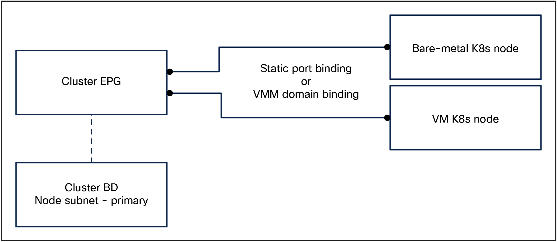
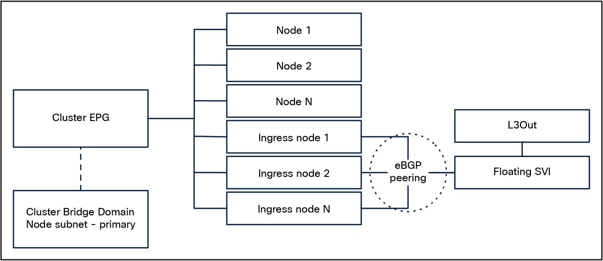
Foundational infrastructure
Cluster EPG physical connectivity
There is no strict requirement of the physical connectivity for the cluster EPG as long as it provides the required redundancy level. Most designs are likely to lean toward a vPC based design.
Selective BGP peering for service advertisement
In this design, a dedicated Cisco ACI L3Out is created for external service advertisement for a subset of Kubernetes nodes that will be, from now on, called “ingress nodes.”
These nodes will be configured with two interfaces. It is convenient to keep the ingress nodes in the cluster EPG, because it simplifies node-to-node communication and allows the use of DHCP relay for node provisioning.
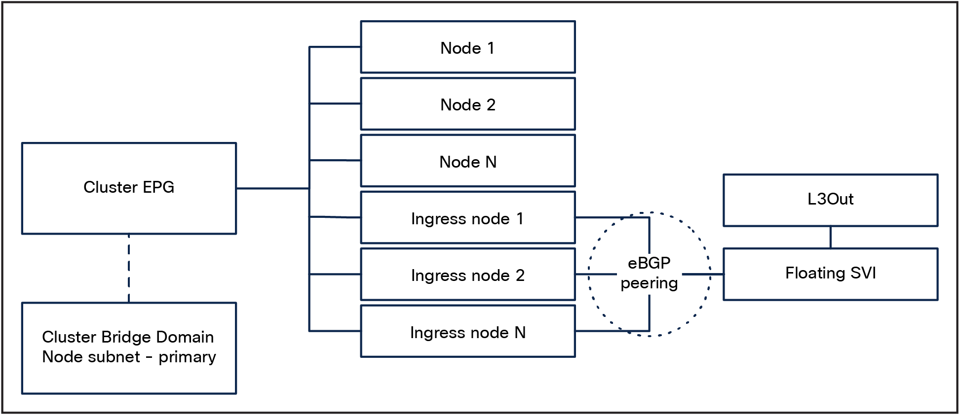
Selective BGP peering architecture
L3Out physical connectivity
There is no strict requirement of the physical connectivity for the L3Out as long as it provides the required redundancy level.
This design implements L3 connectivity with the use of the floating SVI feature. This feature allows us to configure an L3Out without specifying logical interfaces, thus removing the need to configure multiple L3Out logical interfaces to maintain routing when VMs move from one host to another. Floating SVI is supported for VMware vSphere Distributed Switch (VDS) as of Cisco ACI Release 4.2(1) and on physical domains as of Cisco ACI Release 5.0(1). It is recommended to use the physical domains approach for the following reasons:
● It can support any hypervisor.
● It can support mixed mode clusters (VMs and bare-metal).
This is not a strict requirement, and, if all nodes are running in a VMware environment, there are no technical reasons not to use VMM integration.
Using floating SVI also relaxes the requirement of not having any Layer-2 communications between the ingress nodes; this allows the design to use:
● A single subnet for all the ingress nodes
● A single encapsulation (VLAN) for all the ingress nodes
Due to a limitation in ACI, an additional requirement for this design is to peer the ingress nodes with directly attached anchor nodes: routes generated by nodes directly connected to the anchor nodes are preferred over routes from nodes not directly connected to the anchor nodes, and this could lead to nodes not being utilized.
For example: if we have exposed, from our ingress nodes, a service with IP 1.1.1.1 over BGP, as shown in Figure 78, anchor leaf101 will only install one ECMP path for 1.1.1.1/32 through 192.168.2.1, because the locally attached route is preferred.
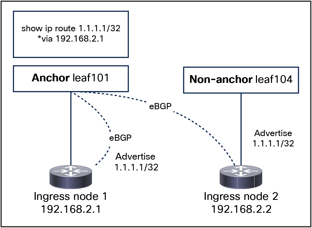
Floating SVI and non-directly attached nodes
In practice, this means that, if we are using VMs for ingress nodes, we need to ensure that they cannot be migrated to a host not directly connected to the anchor nodes selected for BGP peering. This partially voids one of the main benefits of using floating SVI; however, a future ACI release will address this limitation.
ACI BGP design
From a BGP design perspective, we will take advantage of the following features:
BGP Dynamic Neighbors
All the ingress nodes will share the same AS number. By sharing the same AS number, we can use the BGP Dynamic Neighbors capability, which allows for the dynamic and automated establishment of peering sessions between routers. Instead of requiring manual configuration of individual neighbor statements for each peer, this feature utilizes a "listener" (in our case, the ACI fabric) to accept incoming BGP connections from a predefined IP subnet.
BGP Graceful Restart
Both ACI and Cilium will be configured to use BGP Graceful Restart. When a BGP speaker restarts its BGP process or when the BGP process crashes, neighbors will not discard the received paths from the speaker, ensuring that connectivity is not impacted as long as the data plane is still correctly programmed.
BGP timers tuning
Currently, Cilium does not support Bidirectional Forwarding Detection (BFD), so, to achieve faster convergence, we must rely on BGP timers tuning. Since the number of ingress nodes is limited, this should not pose any scalability issues on the border leaves.
The ACI BGP timers should be set to 1s/3s to ensure faster convergence.
Max BGP ECMP path (optional)
By default, ACI installs up to 16 eBGP/iBGP ECMP paths. If more than 16 ingress nodes are required, ACI can be configured to install up to 64 ECMP paths.
BGP hardening (optional)
To protect the ACI system against potential Kubernetes BGP misconfigurations, the following settings are recommended:
● Enable BGP password authentication
● Set the maximum AS limit to one:
◦ Per the eBGP architecture, the AS path should always be one.
● Configure BGP import route control to accept only the expected external-services subnets.
● (Optional) Set a limit on the number of received prefixes from the nodes.
Cilium BGP design
When it comes to the Cilium BGP design, the only real decisions we must make are how many ingress nodes to deploy and whether or not we want to dedicate them only for this purpose.
Ideally, we want to have a minimum of two ingress nodes distributed between two pairs of anchor nodes. This will provide redundancy in case of ingress node or ACI leaf failure or during upgrades.
Depending on the cluster scale and application requirements, dedicated ingress nodes could be beneficial for the following reasons:
● Consistent latency: if no Pods are running on the ingress node, latency will always be the same: all the ingress traffic will reach the target Pod through two hops.
● Limit the number of ingress nodes: By having dedicated ingress nodes, we can ensure that all the bandwidth and compute are dedicated to the ingress function.
● Specialized hardware: not all the nodes in a Kubernetes clusters need to be the same; specialized high-performance hardware can be utilized for our ingress nodes. For example, thanks to CiliumNodeConfig,[6] we can deploy bare-metal nodes with wither Mellanox or Intel® network interface cards and achieve 100+ Gbps throughput per ingress node, thanks to Cilium Big TCP capability. [7]
For small clusters or labs, there is no need to have dedicated ingress nodes.
To selectively enable BGP and ensure that we peer with the “correct” anchor nodes (that is, ones that are directly attached), we can use CiliumBGPPeeringPolicy and matchLabels to select leaves and ingress node groups.
Refer to the “Example configuration - OpenShift, Multi-Pool, L2 Pod Advertisement, and BGP Advertisement” section of this document for implementation details.
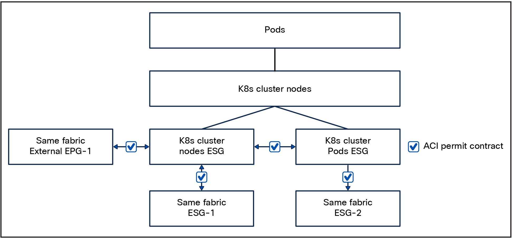
Layer-2 Pod Announcements advertise the pod IP addresses within the Layer-2 network domain, utilizing Gratuitous Address Resolution Protocol (GARP). When enabled, the node transmits gratuitous ARP replies for every locally created Pod on the configured network interface.
In Cisco ACI, we can take advantage of this behavior, as described below:
1. Create a Bridge Domain (BD) with a two subnets configured:
a. The node subnet, and set this as primary, ensuring we can enable DHCP relay.
b. The Pod subnet, as defined in the Cilium configuration
2. Create an Endpoint Group (EPG) that is associated with the aforementioned BD.
3. Create two Endpoint Security Groups (ESGs):
a. A node ESG with an IP-subnet-based selector that correlates with the node subnet.
b. A Pod ESG with an IP-subnet-based selector that aligns with the Pod subnet.

Cluster-Pool: pod visibility
This configuration enables the segregation and independent security management of node and Pod traffic using contracts while concurrently maintaining Pod IP visibility within the network fabric.
Pod-to-node communication is expected to be unrestricted, therefore the node and POD ESGs need to be configured with a contract that allows unrestricted communication or are placed in the same preferred group. Note that having different preferred groups in the same VRF is not allowed., and an ESG/EPG can be a member, though it does not have to be. This does not allow having different preferred groups in the same VRF; as such, it is not recommended.
Additionally, we need to ensure that no Pod will ever use as an IP address one already used in the ACI BD: Cilium does not have any capability to exclude one IP from the PodCIDRs nor to learn of such an address in the ACI BD.
This issue is, however, easily addressed:
Consider, for instance, a desired configuration such as the following:
● clusterPoolIPv4PodCIDRList=10.52.0.0/16
● ipv4NativeRoutingCIDR=10.52.0.0/16
● clusterPoolIPv4MaskSize=/24
● ACI BD subnet with Switch Virtual Interface (SVI): 10.52.255.254/16
We need to ensure that Cilium will never allocate to a Pod the 10.52.255.254 address.
Cilium allocates PODs CIDRto the Kubernetes nodes by splitting the clusterPoolIPv4PodCIDRList by clusterPoolIPv4MaskSize.
For example, based on the above configuration, our nodes will get per node podCIDR subnets like these: 10.52.0.0/24,10.52.1.0/24, etc.
Furthermore, Cluster-Pool supports having one or more subnets in the PodCIDRList, allowing us to define the clusterPoolIPv4PodCIDRList as a list of the following subnets:
● 10.52.0.0/17
● 10.52.128.0/18
● 10.52.192.0/19
● 10.52.224.0/20
● 10.52.240.0/21
● 10.52.248.0/22
● 10.52.252.0/23
● 10.52.254.0/24
In practice, this results in the exclusion of 10.52.255.0/24 from the 10.52.0.0/16 clusterPoolIPv4PodCIDRList, ensuring that 10.52.255.254 is never going to be allocated to a Pod. The only disadvantages of this configuration are wasting a clusterPoolIPv4MaskSize subnet and the requirement to configure the clusterPoolIPv4PodCIDRList with multiple subnets.
Note: To keep the clusterPoolIPv4PodCIDRList as easy to manage as possible, it is recommended to allocate to ACI either the first or the last IP in the subnet.
Currently, a Cilium issue has been opened to enhance this configuration: https://github.com/cilium/cilium/issues/31600
Warning: Both Cluster-Pool and Multi-Pool will generate duplicate IPs and routing loops if the nodes are not configured correctly. Please refer to Cluster-Pool and Multi-Pool node-routing requirements.
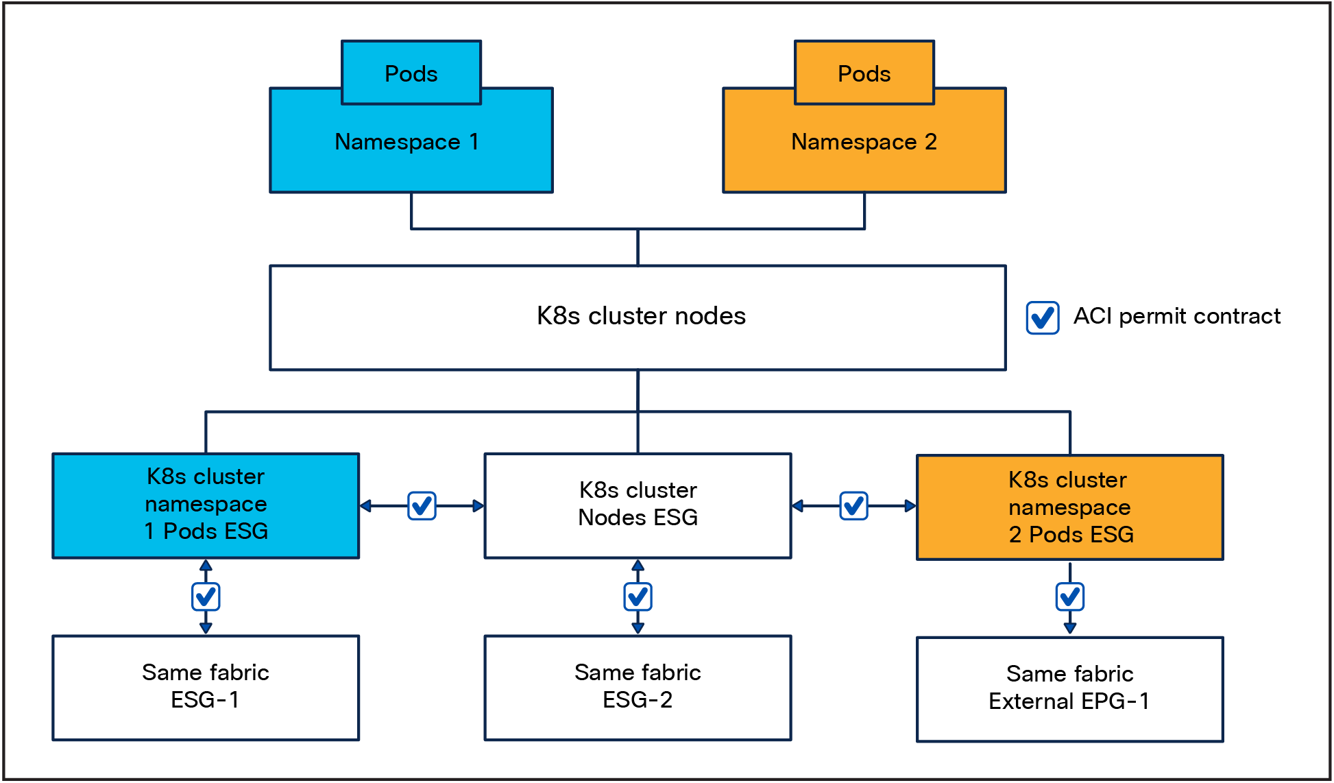
Multi-Pool: pod visibility and security
The design for Multi-Pool follows the same principle of the one for Cluster-Pool; however, since the Multi-Pool IPAM mode supports allocating PodCIDRs (from multiple different IPAM pools) to different namespaces, we can now easily create namespace-to-ESG mappings by using an ESG subnet selector.
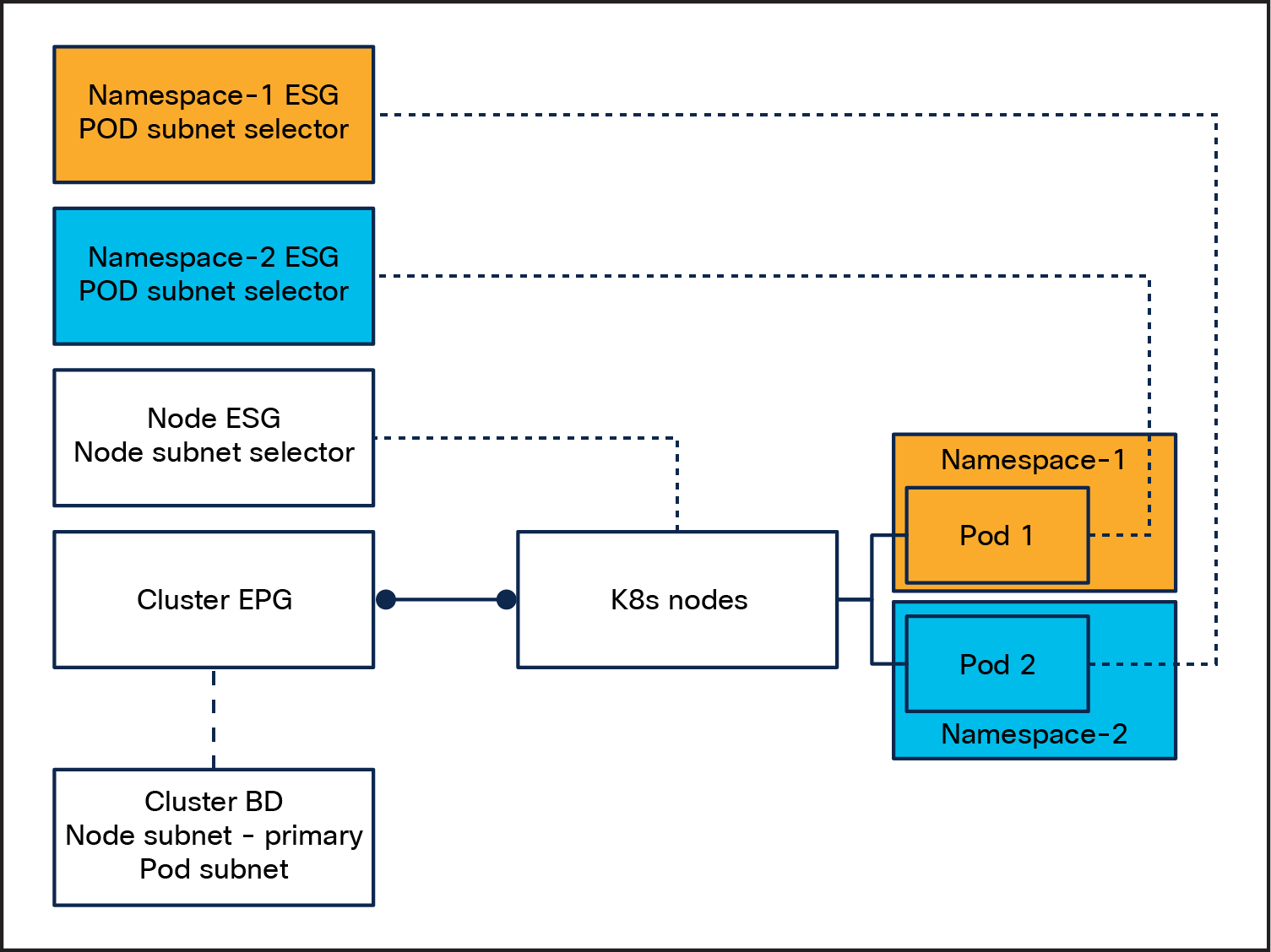
Multi-Pool pod visibility and per-namespace security
Similarly to what we did for Cluster-Pool, we need to ensure that Cilium will never allocate to a Pod the ACI BD SVI address. Furthermore, it is recommended to have a “default” POD CIDR pool that will be used when the ipam.cilium.io/ip-pool is not present. This is particularly convenient in the case of OpenShift where several Pods will need to be running as part of the cluster bootstrap process.
Let’s assume for our cluster that we want to use the 10.52.0.0/16 as ipv4NativeRoutingCIDR.
● Create a “default” Pod IP pool in the 10.52.0.0/17 subnet. This will be the default subnet the Pods will use.
● As needed, carve out the 10.52.128.0/17 subnet to create additional POD CIDR pools that can be selected with the ipam.cilium.io/ip-pool annotation.
● Create new ESGs in ACI that match the “new” POD CIDR pools.
● Do not allocate to a POD CIDR pools a subnet that contains the ACI BD address.
Multi-Pool CIDR size and nodes
When configuring Pod pools, it is important to remember that Pod scheduling is managed by the Kubernetes scheduler, and the Pod IP pool allocation to a Kubernetes node is managed by Cilium.
These two components do not talk or influence each other’s, and, every time a Pod is started on a node, Cilium will select a maskSize subnet from the Pod pool and allocate it to the node (unless is already allocated).
If there are more Kubernetes nodes than maskSize subnets inside the Pod pool, it is possible that the Kubernetes scheduler will schedule a Pod on a node that has no POD CIDR available, resulting in the Pod never reach the run stage.
To avoid this issue, we can:
● Pick a Pod pool that is large enough for every node to get a maskSize subnet.
● Influence the Kubernetes scheduler: this can be done by using node labels to select only a subset of the nodes when scheduling an application that is using a specific Pod pool.
Note: This behaviour is standard in Kubernetes and can be seen even without the use of Multi-Pool. In general, this is a nonissue because we tend to allocate /16 or larger subnets as POD CIDRs.
Warning: Both Cluster-Pool and Multi-Pool will generate duplicate IPs and routing loops if the nodes are not configured correctly. Please refer to Cluster-Pool and Multi-Pool node-routing requirements
Cluster-Pool and Multi-Pool node-routing requirements
With both Cluster-Pool and Multi-Pool, loops and duplicate IPs will happen under the following circumstances:
● Cluster-Pool:
◦ When a Kubernetes node(s) is reloaded
● Multi-Pool:
◦ When a Kubernetes node(s) is reloaded
◦ When a Pod is no longer on a node but traffic is still being sent to the nonexistent Pod
The root cause is that the Pod endpoint learned by ACI will not age-out immediately, and any traffic directed to a non-existing Pod IP will still be forwarded to the Kubernetes node.
The node receiving the traffic, not having a Pod running anymore with that IP, will return the traffic back to ACI, following the default route. This will lead to routing loops, and in both cases ACI Rogue EP Control will be triggered and the whole cluster connectivity will be impacted.
Note: This is a simplified explanation, and there are differences in the behavior of Cluster-Pool vs. Multi-Pool. A detailed root-cause analysis is available in this GitHub issue: https://github.com/cilium/cilium/issues/31079.
The solution is quite simple: When using L2 Pod Subnet advertisement, ALL your Kubernetes nodes need to have a blackhole route (route to null) for the ipv4NativeRoutingCIDR.
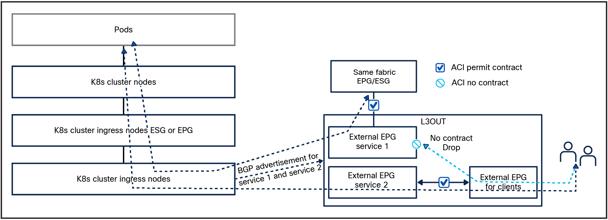
This design aims to provide you with an easy and high scalable design; however, it comes with the following drawbacks:
1. External services can only be advertised as “Cluster Scope”: since all the incoming traffic has to pass through a subset of Kubernetes nodes, we need to be able to perform a second-stage load balancing to reach the “correct” node.
2. Potential bottle necks for ingress traffic
3. BGP cannot be used anymore to advertise the Pod subnets.
For issue (1) there is no solution; this is a trade-off we make to achieve a more scalable and simple design. Issue (2) can be easily addressed with either vertical or horizontal scaling, as detailed in the “Cilium BGP design” section in this document.
Issue (3) can be addressed with Cilium L2 Pod Announcements: This feature uses gratuitous ARP to advertise the Pod IPs to the network, bypassing the need for each node to participate in BGP peering.
This design has been tested on the following Kubernetes distributions:
OpenShift
The design works correctly on OpenShift except for two issues, both with easy workarounds:
1. There is currently an RBAC issue on Cilium manifests for OpenShift. The workaround is to patch the cluster-network-06-cilium-00009-cilium-cilium-clusterrole.yaml file and add the following additional permissions:
- apiGroups:
- ""
resources:
- secrets
verbs:
- get
- list
- watch
2. Even if NMState supports setting blackhole routes, OpenShift Assisted Installer will fail, displaying the following error:
Invalid YAML string: unknown field route-type, expected one of state, destination, next-hop-interface, next-hop-address, metric, table-id, weight, err_kind: InvalidArgument
The blackhole route can be added once the cluster is installed, using an NodeNetworkConfigurationPolicy. In my testing, a cluster bootstrap completed successfully even without the “blackhole” route for the POD CIDR; however, especially in a production environment, it is recommended to add this route manually on all the nodes during the bootstrap process.
This can be done by connecting to every node with SSH and issuing this command:
| ip route add blackhole <POD_CIDR> |
Note: During installation, the nodes will reload once; adding the route is required after the first reload.
Once the cluster is successfully bootstrapped, you can install the NMState Operator and add this config to ensure that the blackhole route will always be present:
| kind: NodeNetworkConfigurationPolicy metadata: name: additional-routes spec: nodeSelector: kubernetes.io/os: linux desiredState: routes: config: - destination: <POD_CIDR> route-type: blackhole |
Note: Since I need this route on all the nodes, and since all my nodes are Linux-based, I am using as nodeSelector the label kubernetes.io/os=linux. This might need to be changed depending on your specific environment.
Upstream Kubernetes
The design works correctly on Upstream Kubernetes.
Depending on the version of Linux OS chosen, the way to configure the blackhole route and the ip-rules might be different:
● On distribution, where NetworkManager is present, you can install the NMState Operator and use the same config as shown in the example above.
● If you have direct access to the Linux networking config, you can simply add the routes/rules manually.
● If you are using a version of Linux OS that does not support editing the ip rules manually (for example, for Cisco® Talos® Linux, see this issue) a possible solution is to run a privileged daemon set on the nodes to set the ip-rules. A possible open-source approach is provided here: https://github.com/camrossi/cilium-secondary-interface-route-manager.
Note: The above code is provided as is and is not supported by Cisco TAC.
The above list is not exhaustive and shows just a few possibilities.
Example configuration - OpenShift, Multi-Pool, L2 Pod Advertisement, and BGP Advertisement
This example assumes you are familiar with OpenShift, OpenShift Assisted Installer, and have bootstrapped OpenShift clusters in the past.
Note: DHCP relay is not used for this example.
This cluster will be composed of
● 3x primary nodes
● 4x dedicated worker nodes
● 2x dedicated ingress nodes
The following subnets will be used:
● Node subnet: 192.168.2.16/28
● Pod subnet: 10.53.0.0/16
◦ Default Pod subnet 10.53.0.0/17
◦ App-1 Pod subnet: 10.53.128.0/24
◦ App-2 Pod subnet: 10.53.129.0/24
◦ ACI Pod SVI: 10.53.255.254/16
● BGP peering subnet: 192.168.2.0/28
● Load-balancer services pool: 192.168.2.32/28
Note: In this example, the cluster will be placed in a dedicated tenant called openshift-cilium-c1 and will use a pre-existing VRF “k8s” in the common tenant.
A high-level topology is show below, the tenant and VRF are not shown for simplicity.
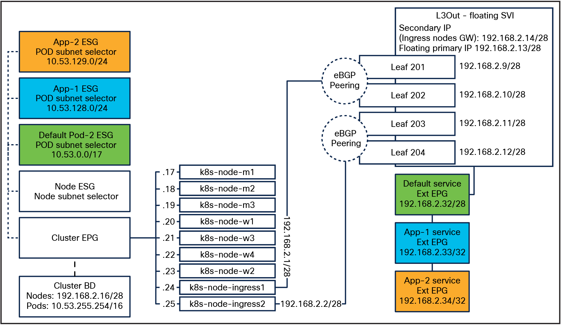
OpenShift topology
● The fabric access policies / VMM domains must already be in place for your OpenShift nodes.
● To successfully bootstrap an OpenShift cluster, both the node and the Pod subnets need to have internet access. How this is achieved is environment dependent.
1. Create a new “openshift-cilium-c1” tenant. All of the subsequent config is placed inside this tenant.
2. Create a new “cluster” BD.
a. Note: In this example, this BD is mapped to a pre-existing VRF in the common tenant. You will need to create your own VRF.
b. Add the nodes subnet SVI 192.168.2.30/28 as the primary subnet.
c. Add an additional Pod subnet SVI: 10.53.255.254/16.
3. Create a new “cluster” application profile.
a. Create a “cluster” EPG and provision connectivity to your OpenShift node through VMM and/or static port binding.
b. Create a “contract-master” ESG:
i. Set the ESG admin state to “Admin Shut.” This ESG is not expected to carry any traffic and will only be used as a contract master ESG.
ii. Add a “permit-all” contract in both the consumer and provider direction. This will be used to ensure that bidirectional communication is allowed between the nodes and the Pods.
This is required because, in any Kubernetes cluster, all the Pods need to be able to communicate with the DNS service. Additionally, OpenShift deploys several operators that will need to access the KubeAPI, node statistics, etc. Providing unrestricted communication within the cluster is hence the preferred approach. This is also the default behavior of any Kubernetes cluster.
iii. When creating the ESGs in the following steps, select the “contract-master” ESG as ESG contract master.
c. Create a “nodes” ESG and use the 192.168.2.16/28 as IP subnet selector.
i. Add contracts to allow internet connectivity, because OpenShift requires this to operate correctly.
d. Create a “default-pods” ESG and use the 10.53.0.0/17 as IP subnet selector.
i. Add contracts to allow internet connectivity, because OpenShift requires this to operate correctly.
e. Create an “app-1-pods” ESG and use the 10.53.128.0/24 as IP subnet selector.
f. Create an “app-2-pods” ESG and use the 10.53.129.0/24 as IP subnet selector.
4. Create a new BGP Timers Policy and set the following parameters:
a. Keep-alive interval: 1s
b. Hold interval: 3s
c. Maximum AS limit: 1
d. Leave the rest as default.
5. Create a new L3Out called “services.” This will be configured using floating SVIs.
a. Create a new “Node Profile” and add you anchor nodes to it; in this example. I have 4 anchor nodes, as shown in Figure 9
b. Configure a floating interface profile with 4 floating-SVI interfaces, one for each node.
i. Add a BGP peer connectivity profile for the 192.168.2.0/28 subnet. Select a BGP remote AS for your cluster; in this example, we are going to use 65112. Leave all the other options as default.
ii. Create a “default_svc” external EPG for the load-balancer services pool: 192.168.2.32/28, and set this subnet as “External Subnets for External EPG.”
iii. Create an “app1_svc” external EPG for the load-balancer services: 192.168.2.33/32, and set this subnet as “External Subnets for External EPG.”
iv. Create an “app2_svc” external EPG for the load-balancer services: 192.168.2.34/32, and set this subnet as “External Subnets for External EPG.”
v. Depending on your lab config, you should also add contracts to these 3 external EPGs to provide connectivity toward your clients.
c. Create a “BGP Protocol Profile” by clicking on Node Profile that you created.
i. Apply the BGP timers policy.
This concludes the ACI configuration. The fabric should be ready to accept your workloads.
In this example, I am deploying OpenShift 4.15 with Assisted Installer[8]. Assisted Installer requires us to create two config files:
● install-config.yaml
● agent-config.yaml
Furthermore, since we are installing Cilium, we also need to prepare an additional folder containing the required Cilium manifests and their customisations.
Note: When openshift-install generates the cluster config, it will delete the source files. I strongly recommend that you create an agent-config folder and an install folder and generate the cluster config by executing the openshift-install against the install folder after copying the content from the agent-config folder in it.
Install-config
The difference from a standard OpenShift installation is the networkType: Cilium setting.
| apiVersion: v1 baseDomain: cam.ciscolabs.com compute: - name: worker replicas: 6 controlPlane: name: master replicas: 3 metadata: name: ocp-cilium-c1 networking: machineNetwork: - cidr: 192.168.2.16/28 clusterNetwork: - cidr: 10.53.0.0/16 hostPrefix: 27 networkType: Cilium serviceNetwork: - 172.30.0.0/16 platform: baremetal: apiVIPs: - 192.168.2.29 ingressVIPs: - 192.168.2.28 fips: false pullSecret: '<youPullSecret>' sshKey: 'ssh-rsa <yourkey>' |
Agent-Config
The difference from a standard OpenShift Installation is the following:
The ingress nodes are configured with an additional interface for the L3Out peering, and additional static route and route-rules as described in the “Cilium Cilium BGP Control Plane” section of this document. In this example, we will have two route-rules sending traffic from the node service interface “192.168.2.<nodeIP>/32” and our CiliumLoadBalancerIPPool pool 192.168.2.32/28 to route-table 101.
Note: If you add more than one CiliumLoadBalancerIPPool, you will need to add them as additional rules. You can use a NMState NodeNetworkConfigurationPolicy for this task.
| apiVersion: v1alpha1 kind: AgentConfig metadata: name: ocp-cilium-c1 rendezvousIP: 192.168.2.17 AdditionalNTPSources: - time.cisco.com hosts: - hostname: ocp-cilium-c1-m1 role: master interfaces: - name: ens192 macAddress: 00:50:56:b1:e5:49 networkConfig: interfaces: - name: ens192 type: ethernet state: up mac-address: 00:50:56:b1:e5:49 ipv4: enabled: true address: - ip: 192.168.2.17 prefix-length: 28 dhcp: false ipv6: enabled: false dns-resolver: config: server: - 10.67.185.100 routes: config: - destination: 0.0.0.0/0 next-hop-address: 192.168.2.30 next-hop-interface: ens192 - hostname: ocp-cilium-c1-m2 role: master interfaces: - name: ens192 macAddress: 00:50:56:b1:82:30 networkConfig: interfaces: - name: ens192 type: ethernet state: up mac-address: 00:50:56:b1:82:30 ipv4: enabled: true address: - ip: 192.168.2.18 prefix-length: 28 dhcp: false ipv6: enabled: false dns-resolver: config: server: - 10.67.185.100 routes: config: - destination: 0.0.0.0/0 next-hop-address: 192.168.2.30 next-hop-interface: ens192 - hostname: ocp-cilium-c1-m3 role: master interfaces: - name: ens192 macAddress: 00:50:56:b1:70:90 networkConfig: interfaces: - name: ens192 type: ethernet state: up mac-address: 00:50:56:b1:70:90 ipv4: enabled: true address: - ip: 192.168.2.19 prefix-length: 28 dhcp: false ipv6: enabled: false dns-resolver: config: server: - 10.67.185.100 routes: config: - destination: 0.0.0.0/0 next-hop-address: 192.168.2.30 next-hop-interface: ens192 - hostname: ocp-cilium-c1-w1 role: worker interfaces: - name: ens192 macAddress: 00:50:56:b1:a0:10 networkConfig: interfaces: - name: ens192 type: ethernet state: up mac-address: 00:50:56:b1:a0:10 ipv4: enabled: true address: - ip: 192.168.2.20 prefix-length: 28 dhcp: false ipv6: enabled: false dns-resolver: config: server: - 10.67.185.100 routes: config: - destination: 0.0.0.0/0 next-hop-address: 192.168.2.30 next-hop-interface: ens192 - hostname: ocp-cilium-c1-w2 role: worker interfaces: - name: ens192 macAddress: 00:50:56:b1:b9:ea networkConfig: interfaces: - name: ens192 type: ethernet state: up mac-address: 00:50:56:b1:b9:ea ipv4: enabled: true address: - ip: 192.168.2.21 prefix-length: 28 dhcp: false ipv6: enabled: false dns-resolver: config: server: - 10.67.185.100 routes: config: - destination: 0.0.0.0/0 next-hop-address: 192.168.2.30 next-hop-interface: ens192 - hostname: ocp-cilium-c1-w3 role: worker interfaces: - name: ens192 macAddress: 00:50:56:b1:41:78 networkConfig: interfaces: - name: ens192 type: ethernet state: up mac-address: 00:50:56:b1:41:78 ipv4: enabled: true address: - ip: 192.168.2.22 prefix-length: 28 dhcp: false ipv6: enabled: false dns-resolver: config: server: - 10.67.185.100 routes: config: - destination: 0.0.0.0/0 next-hop-address: 192.168.2.30 next-hop-interface: ens192 - hostname: ocp-cilium-c1-w4 role: worker interfaces: - name: ens192 macAddress: 00:50:56:b1:55:35 networkConfig: interfaces: - name: ens192 type: ethernet state: up mac-address: 00:50:56:b1:55:35 ipv4: enabled: true address: - ip: 192.168.2.23 prefix-length: 28 dhcp: false ipv6: enabled: false dns-resolver: config: server: - 10.67.185.100 routes: config: - destination: 0.0.0.0/0 next-hop-address: 192.168.2.30 next-hop-interface: ens192
- hostname: ocp-cilium-c1-ingress1 role: worker interfaces: - name: ens192 macAddress: 00:50:56:b1:b8:35 networkConfig: interfaces: - name: ens192 type: ethernet state: up mac-address: 00:50:56:b1:b8:35 ipv4: enabled: true address: - ip: 192.168.2.24 prefix-length: 28 dhcp: false ipv6: enabled: false - name: ens224 description: Interface for BGP Peering type: ethernet state: up ipv4: dhcp: false address: - ip: 192.168.2.1 prefix-length: 28 enabled: true dns-resolver: config: server: - 10.67.185.100 routes: config: - destination: 0.0.0.0/0 next-hop-address: 192.168.2.30 next-hop-interface: ens192 - destination: 0.0.0.0/0 next-hop-address: 192.168.2.11 next-hop-interface: ens224 table-id: 101 route-rules: config: - ip-from: 192.168.2.1/32 route-table: 101 - ip-from: 192.168.2.32/28 route-table: 101 - hostname: ocp-cilium-c1-ingress2 role: worker interfaces: - name: ens192 macAddress: 00:50:56:b1:56:d0 networkConfig: interfaces: - name: ens192 type: ethernet state: up mac-address: 00:50:56:b1:56:d0 ipv4: enabled: true address: - ip: 192.168.2.25 prefix-length: 28 dhcp: false ipv6: enabled: false - name: ens224 description: Interface for BGP Peering type: ethernet state: up ipv4: dhcp: false address: - ip: 192.168.2.2 prefix-length: 28 enabled: true dns-resolver: config: server: - 10.67.185.100 routes: config: - destination: 0.0.0.0/0 next-hop-address: 192.168.2.30 next-hop-interface: ens192 - destination: 0.0.0.0/0 next-hop-address: 192.168.2.11 next-hop-interface: ens224 table-id: 101 route-rules: config: - ip-from: 192.168.2.2/32 route-table: 101 - ip-from: 192.168.2.32/28 route-table: 101 |
As explained in the supported-platform section for OpenShift once the cluster is bootstrapped, we need to add the blackhole for the POD CIDR.
| apiVersion: nmstate.io/v1 kind: NodeNetworkConfigurationPolicy metadata: name: pod-blackhole spec: nodeSelector: kubernetes.io/os: linux desiredState: routes: config: - destination: 10.53.0.0/16 route-type: blackhole |
Normally, Cilium is installed after the Kubernetes cluster is bootstrapped, but for OpenShift, there is a strict requirement for any CNI plug-in to be installed together with the cluster bootstrap.
To do so, we can follow the following procedure. Below, I have it summarized and slightly adapted to work with Assisted Installer:
1. Obtain the Cilium manifest:
cd /tmp
git clone https://github.com/isovalent/olm-for-cilium.git
2. Copy the manifest for the required Cilium version in the OpenShift config folder.
Note: openshift-install requires additional manifests to be placed in a folder called “openshift.”
cp /tmp/olm-for-cilium/manifests/cilium.v1.15.1/* ./ocp-cilium-c1/config/openshift
3. Due to the following issue, we need to manually patch the manifests; this is needed to have the BGP Control Plane working.
Edit the cluster-network-06-cilium-00009-cilium-cilium-clusterrole.yaml file and add the following:
| - apiGroups: - "" resources: - secrets verbs: - get - list - watch |
4. Edit the cluster-network-07-cilium-ciliumconfig.yaml to configure Cilium and configure as follows:
| apiVersion: cilium.io/v1alpha1 kind: CiliumConfig metadata: name: cilium namespace: cilium spec: ipam: mode: "multi-pool" operator: autoCreateCiliumPodIPPools: default: ipv4: cidrs: - 10.53.0.0/17 maskSize: 27 ipv4NativeRoutingCIDR: "10.53.0.0/16" enableIPv4Masquerade: false endpointRoutes: enabled: true autoDirectNodeRoutes: true ### Not supported on VMs # loadBalancer: # acceleration: "native" l2podAnnouncements: enabled: true interface: ens192 routingMode: "native" bgpControlPlane: enabled: true cni: binPath: "/var/lib/cni/bin" confPath: "/var/run/multus/cni/net.d" prometheus: serviceMonitor: {enabled: false} hubble: tls: {enabled: false} securityContext: privileged: true sessionAffinity: true kubeProxyReplacement: true k8sServiceHost: api-int.ocp-cilium-c1.cam.ciscolabs.com k8sServicePort: '6443' k8sClientRateLimit: qps: 2 burst: 4 |
Cluster bootstrap and preparation
You can now generate your Assisted Installer ISO image using the following command:
cp -R config/* install
openshift-install agent create image --dir install/
Once the ISO is generated, you can follow the Assisted Installer procedure and just boot your OpenShift nodes.
Note: Once the cluster is up, please remember to add the blackhole routes through NMState. Failure to do so will result in an unstable cluster.
BGP configuration
The main goals for this example are the following:
1. To ensure that the ingress nodes are not running any POD, you can use a node taint. In this example, I use NoExecute;[9] this will terminate any Pod running on my ingress nodes. This is useful because the ingress nodes have been provisioned during cluster bootstrap and will be running some Pods.
oc adm taint node <nodes> dedicated=ingress:NoExecute
2. ocp-cilium-c1-ingress1 peers with leaves 201 and 202. This requirement can be met by labelling the node and creating a CiliumBGPPeeringPolicy that selects the nodes based on this label and ensures that each node peers only with Leaf201 and 202.
oc label node ocp-cilium-c1-ingress1 bgp=ingress-201-202
3. ocp-cilium-c1-ingress2 peers with leaves 203 and 204.
oc label node ocp-cilium-c1-ingress2 bgp=ingress-203-204
4. Services with a “type:bgp” label are going to be advertised. This requirement can be met by creating a CiliumBGPPeeringPolicy that selects the services based on this label.
| apiVersion: "cilium.io/v2alpha1" kind: CiliumBGPPeeringPolicy metadata: name: bgp-peering-policy-201-202 spec: # CiliumBGPPeeringPolicySpec nodeSelector: matchLabels: bgp: ingress-201-202 virtualRouters: # []CiliumBGPVirtualRouter - localASN: 65112 exportPodCIDR: false serviceSelector: matchLabels: type: bgp neighbors: # []CiliumBGPNeighbor - peerAddress: '192.168.2.9/28' peerASN: 65002 gracefulRestart: enabled: true - peerAddress: '192.168.2.10/28' peerASN: 65002 gracefulRestart: enabled: true --- apiVersion: "cilium.io/v2alpha1" kind: CiliumBGPPeeringPolicy metadata: name: bgp-peering-policy-203-204 spec: # CiliumBGPPeeringPolicySpec nodeSelector: matchLabels: bgp: ingress-203-204 virtualRouters: # []CiliumBGPVirtualRouter - localASN: 65112 exportPodCIDR: false serviceSelector: matchLabels: type: bgp neighbors: # []CiliumBGPNeighbor - peerAddress: '192.168.2.11/28' peerASN: 65002 gracefulRestart: enabled: true - peerAddress: '192.168.2.12/28' peerASN: 65002 gracefulRestart: enabled: true |
After applying the above configuration, you should be able to see the BGP peering that has been established with the ACI leaves:
For example, here we can see BGP peering on leaf 201 from the ocp-cilium-c1-ingress node:
fab2-apic1# fabric 201 show ip bgp summary vrf common:k8s
----------------------------------------------------------------
Node 201 (Leaf201)
----------------------------------------------------------------
BGP summary information for VRF common:k8s, address family IPv4 Unicast
BGP router identifier 1.1.1.201, local AS number 65002
BGP table version is 593, IPv4 Unicast config peers 6, capable peers 3
55 network entries and 91 paths using 13348 bytes of memory
BGP attribute entries [25/8800], BGP AS path entries [0/0]
BGP community entries [0/0], BGP clusterlist entries [6/24]
Neighbor V AS MsgRcvd MsgSentTblVer InQ OutQ Up/Down State/PfxRcd
192.168.2.1 4 65112 1545 1546593 0 0 00:25:42 0
Configuring additional IP pools
As per our design, we expect to have the following additional subnets configured:
● App-1 Pod Subnet: 10.53.128.0/24
● App-2 Pod Subnet: 10.53.129.0/24
● Load-balancer services pool: 192.168.2.32/28
The first two are Pod subnets, and the last one is a load-balancer one.
The configurations required to generate these pools are shown below.
CiliumPodIPPool
In the config below, we are creating two IP pools called app-1 and app-2 and allocate the 10.53.128.0/24 and 10.53.129.0/24 subnets, respectively. I choose a maskSize of /27. In my cluster, I have four worker nodes, and this maskSize will generate eight subnets in the /24 supernet.
| apiVersion: cilium.io/v2alpha1 kind: CiliumPodIPPool metadata: name: app-1 spec: ipv4: cidrs: - 10.53.128.0/24 maskSize: 27 --- apiVersion: cilium.io/v2alpha1 kind: CiliumPodIPPool metadata: name: app-2 spec: ipv4: cidrs: - 10.53.129.0/24 maskSize: 27 |
CiliumLoadBalancerIPPool
In the config below, we allocate the 192.168.2.32/28 subnet as type CiliumLoadBalancerIPPool. The subnet is configured with a “serviceSelector.matchLabels.pool,” which can be used in our services to select this pool.
| apiVersion: cilium.io/v2alpha1 kind: CiliumLoadBalancerIPPool metadata: name: "bgp-pool-1" spec: blocks: - cidr: "192.168.2.32/28" serviceSelector: matchLabels: pool: bgp-pool-1 |
Deploying an application – parksmap
We are now ready to deploy an application to test our cluster.
We can use the “parksmap” demo application provided by Red Hat. We are going to deploy this application three times.
Default Pod subnet – not advertised.
1. We will be placing our application in the parksmap namespace:
oc create ns parksmap
2. We can now deploy our application using the command and manifest shown below:
oc -n parksmap apply -f <Deployment>
| apiVersion: apps/v1 kind: Deployment metadata: labels: app: parksmap name: parksmap spec: replicas: 4 selector: matchLabels: app: parksmap template: metadata: labels: app: parksmap deployment: parksmap spec: containers: - image: quay.io/openshiftroadshow/parksmap:latest imagePullPolicy: Always name: parksmap ports: - containerPort: 8080 protocol: TCP |
We should now see the following:
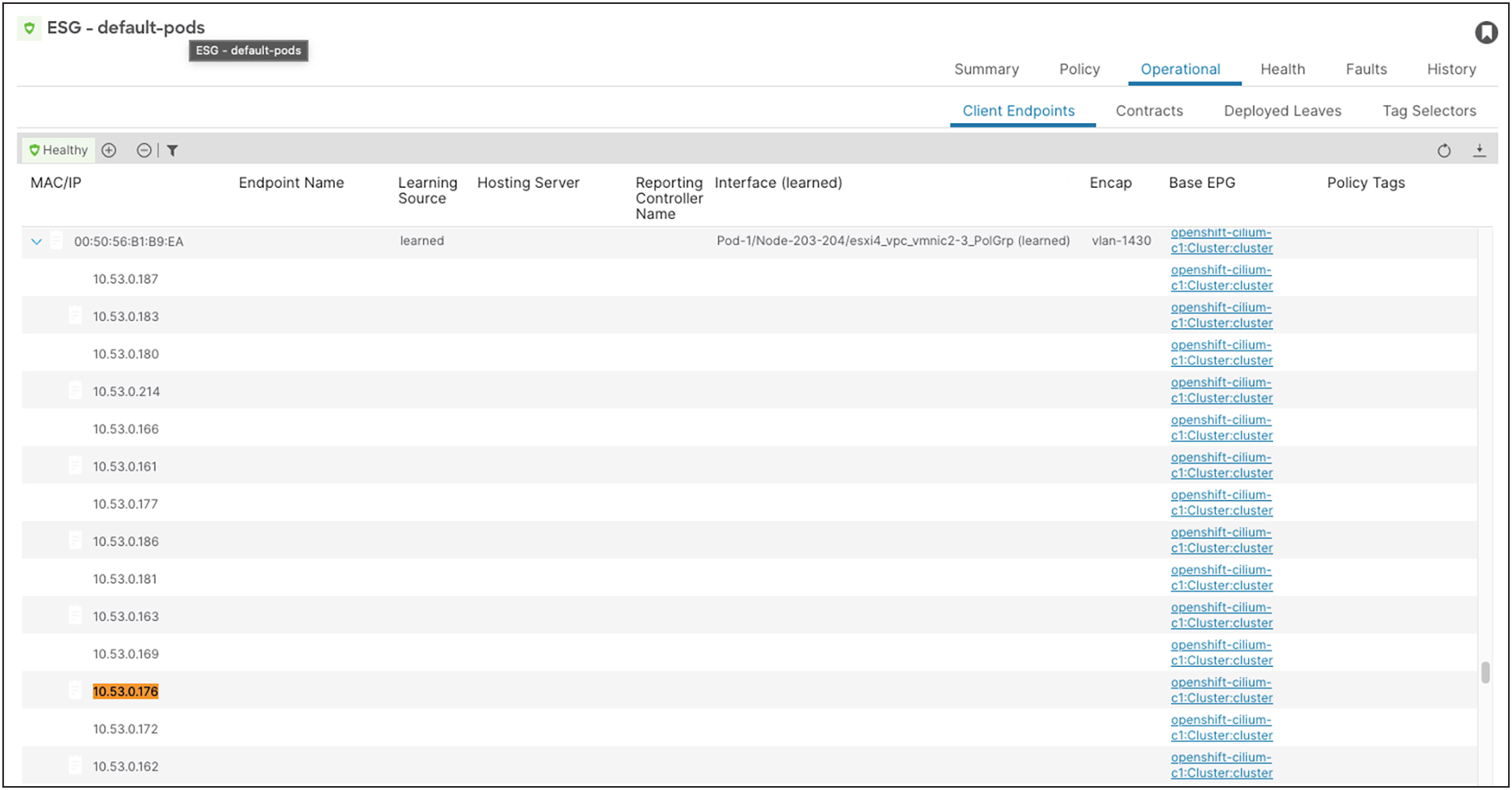
1. We have four Pods running in the default Pod IP pool
oc -n parksmap get pod -o wide
NAME READY STATUS RESTARTS AGE IP NODE NOMINATED NODE
parksmap-7b9889f9bf-95svw 1/1 Running 0 82s 10.53.0.176 ocp-cilium-c1-w2
parksmap-7b9889f9bf-kgjnn 1/1 Running 0 82s 10.53.0.218 ocp-cilium-c1-w1
parksmap-7b9889f9bf-lrz66 1/1 Running 0 82s 10.53.0.226 ocp-cilium-c1-w3
parksmap-7b9889f9bf-nr8l6 1/1 Running 0 82s 10.53.1.30 ocp-cilium-c1-w4
2. ACI is learning these IPs in the default Pod ESG; note that under the same node MAC address, we have multiple IPs because multiple Pods are running on a single node.
App-1 Pod subnet – advertised externally through BGP
1. We will be placing our application in the app-1 namespace:
oc create ns app-1
2. We want to use app-1 CiliumPodIPPool so we can annotate the namespace as follows:
oc annotate ns app-1 ipam.cilium.io/ip-pool=app-1
3. We can now deploy our application using the same deployment manifest as shown in the previous example; just remember to use the right namespace:
oc -n app-1 apply -f <Deployment>
4. To expose our application through BGP, we can create a service of type LoadBalancer and use the following labels:
a. pool: bgp-pool-1 to select our CiliumLoadBalancerIPPool type: bgp to advertise our service through BGP. (The CiliumBGPPeeringPolicy is configured to advertise services that are configured with this label
5. Since ACI is preconfigured with an external EPG with a 192.168.2.33/32 LPM, we can manually select this address from our pool using the io.cilium/lb-ipam-ips annotation.
oc -n app-1 apply -f <Service>
| apiVersion: v1 kind: Service metadata: labels: app: parksmap pool: bgp-pool-1 type: bgp annotations: io.cilium/lb-ipam-ips: "192.168.2.33" name: parksmap spec: ports: - name: 8080-tcp port: 8080 protocol: TCP targetPort: 8080 selector: app: parksmap deployment: parksmap type: LoadBalancer |
We should now see the following:
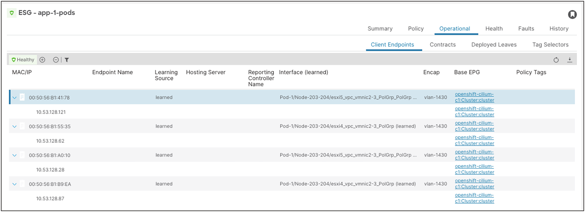
1. We have four Pods running in the app-1 Pod IP pool (10.53.128.0/24):
oc -n app-1 get pod -o wide
NAME READY STATUS RESTARTS AGE IP NODE NOMINATED NODE
parksmap-7b9889f9bf-h7hdh 1/1 Running 0 21s 10.53.128.28 ocp-cilium-c1-w1
parksmap-7b9889f9bf-lnmnw 1/1 Running 0 21s 10.53.128.87 ocp-cilium-c1-w2
parksmap-7b9889f9bf-mkqnp 1/1 Running 0 21s 10.53.128.62 ocp-cilium-c1-w4
parksmap-7b9889f9bf-zrtjx 1/1 Running 0 21s 10.53.128.121 ocp-cilium-c1-w3
2. ACI is learning these IP addresses in the app-1 Pod ESG:
3. A service of type LoadBalancer is created on the cluster with IP 192.168.2.33:
oc -n app-1 get svc
NAME TYPE CLUSTER-IP EXTERNAL-IP PORT(S) AGE
parksmap LoadBalancer 172.30.238.58 192.168.2.33 8080:30867/TCP 107s
4. ACI is receiving /32 routes from the two ingress nodes:
fab2-apic1# fabric 201 show ip route 192.168.2.33 vrf common:k8s
192.168.2.33/32, ubest/mbest: 1/0
*via 192.168.2.1%common:k8s, [20/0], 00:00:26, bgp-65002, external, tag 65112
recursive next hop: 192.168.2.1/32%common:k8s
fab2-apic1# fabric 203 show ip route 192.168.2.33 vrf common:k8s
192.168.2.33/32, ubest/mbest: 1/0
*via 192.168.2.2%common:k8s, [20/0], 00:00:18, bgp-65002, external, tag 65112
recursive next hop: 192.168.2.2/32%common:k8s
5. Assuming your contracts are correct on the app-1 external EPG, you should now be able to access the application.
App-2 Pod subnet – advertised externally through BGP
We can now repeat the exact same steps as in the App-1 example, just selecting a different CiliumPodIPPool and using 192.168.2.34 as the LoadBalancer IP.
1. We will be placing our application in the app-2 namespace:
oc create ns app-2
2. We want to use app-2 CiliumPodIPPool so we can annotate the namespace as follows:
oc annotate ns app-2 ipam.cilium.io/ip-pool=app-2
3. We can now deploy our application using the same deployment manifest as shown in the first example; just remember to use the right namespace:
oc -n app-2 apply -f <Deployment>
4. To expose our application through BGP, we can create a service of type LoadBalancer and use the following labels:
a. pool: bgp-pool-1 to select our CiliumLoadBalancerIPPool type: bgp to advertise our service through BGP. (The CiliumBGPPeeringPolicy is configured to advertise services that are configured with this label
5. Since ACI is preconfigured with an external EPG with a 192.168.2.34/32 LPM, we can manually select this address from our pool using the io.cilium/lb-ipam-ips annotation:
oc -n app-1 apply -f <Service>
| apiVersion: v1 kind: Service metadata: labels: app: parksmap pool: bgp-pool-1 type: bgp annotations: io.cilium/lb-ipam-ips: "192.168.2.34" name: parksmap spec: ports: - name: 8080-tcp port: 8080 protocol: TCP targetPort: 8080 selector: app: parksmap deployment: parksmap type: LoadBalancer |
We should now see the following:
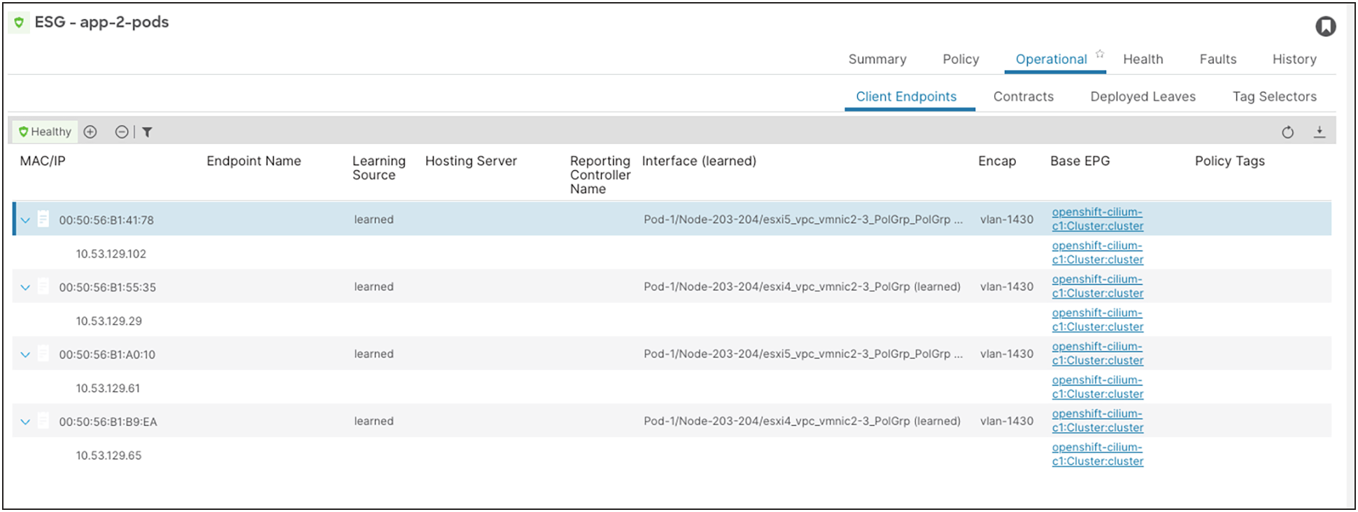
6. We have four Pods running in the app-2 Pod IP pool (10.53.129.0/24):
oc -n app-2 get pod -o wide
NAME READY STATUS RESTARTS AGE IP NODE NOMINATED NODE
parksmap-7b9889f9bf-gkjsn 1/1 Running 0 30s 10.53.129.61 ocp-cilium-c1-w1
parksmap-7b9889f9bf-jqhd8 1/1 Running 0 30s 10.53.129.65 ocp-cilium-c1-w2
parksmap-7b9889f9bf-pqx9w 1/1 Running 0 30s 10.53.129.29 ocp-cilium-c1-w4
parksmap-7b9889f9bf-xbfdr 1/1 Running 0 30s 10.53.129.102 ocp-cilium-c1-w3
7. ACI is learning these IP addresses in the app-2 Pod ESG:
8. A service of type LoadBalancer is created on the cluster with IP 192.168.2.34:
oc -n app-2 get svc
NAME TYPE CLUSTER-IP EXTERNAL-IP PORT(S) AGE
parksmap LoadBalancer 172.30.249.57 192.168.2.34 8080:32671/TCP 13s
9. ACI is receiving /32 routes from the two ingress nodes:
fab2-apic1# fabric 201 show ip route 192.168.2.34 vrf common:k8s
192.168.2.34/32, ubest/mbest: 1/0
*via 192.168.2.1%common:k8s, [20/0], 00:01:10, bgp-65002, external, tag 65112
recursive next hop: 192.168.2.1/32%common:k8s
fab2-apic1# fabric 203 show ip route 192.168.2.34 vrf common:k8s
192.168.2.34/32, ubest/mbest: 1/0
*via 192.168.2.2%common:k8s, [20/0], 00:01:26, bgp-65002, external, tag 65112
recursive next hop: 192.168.2.2/32%common:k8s
10. Assuming your contracts are correct on the app-2 external EPG, you should now be able to access the application.
Pod-initiated traffic
We have now deployed our application in three different Pod subnets and corresponding ESGs on ACI. ACI will be able to policy-egress traffic initiated from the ESGs using standard contracts. Furthermore, since we have disabled masquerading, the Pod IP will be preserved.
For example, if we try to access an external webserver (10.67.185.120 in this example) from a parksmap Pod, we will see the Pod IP address:
oc -n app-1 get pod parksmap-7b9889f9bf-h7hdh -o wide
NAME READY STATUS RESTARTS AGE IP NODE
parksmap-7b9889f9bf-h7hdh 1/1 Running 0 73m 10.53.128.28 ocp-cilium-c1-w1
oc -n app-1 exec parksmap-7b9889f9bf-h7hdh -- curl 10.67.185.120
http-server# tail -f /var/log/nginx/access.log
10.53.128.28 - - [15/Apr/2024:11:22:53 +1000] "GET / HTTP/1.1" 200 3003 "-" "curl/7.29.0"
oc -n app-2 get pod -o wide parksmap-7b9889f9bf-gkjsn
NAME READY STATUS RESTARTS AGE IP NODE
parksmap-7b9889f9bf-gkjsn 1/1 Running 0 24m 10.53.129.61 ocp-cilium-c1-w1
oc -n app-2 exec parksmap-7b9889f9bf-gkjsn -- curl 10.67.185.120
tail -f /var/log/nginx/access.log
10.53.129.61 - - [15/Apr/2024:11:27:25 +1000] "GET / HTTP/1.1" 200 3003 "-" "curl/7.29.0"
Since now the Pod subnet is predictable and allocated to a dedicated namespace, we can leverage this to configure external firewalls.
Note: The best granularity is at the whole POD CIDR; because the Pod IP addresses are ephemeral, DO NOT use Pod IP in any security rule.