Introduction
This document describes the process of onboarding NFVIS capable systems into a Catalyst™ SD-WAN environment for management and operation.
Prerequisites
Requirements
Cisco recommends that you have knowledge of these topics:
- Cisco SDWAN
- NFVIS
- Plug and Play (PNP)
It is presumed that:
- SD-WAN Controllers (vManage, vBond, and vSmart) are already deployed with valid certificates.
- Cisco WAN Edge (NFVIS on this case) has reachability to the vBond orchestrator and other SD-WAN controllers which are reachable via public IP addresses across the WAN transport(s)
- NFVIS version must be compliant with the Control Components Compatibility Guide.
Components Used
The information in this document was created from the devices in a specific lab environment. All of the devices used in this document started with a cleared (default) configuration. If your network is live, ensure that you understand the potential impact of any command.
Hardware
- C8300-UCPE-1N20 (But can be applied to any NFVIS capable platform)
Software
- vManage 20.14.1
- vSmart & vBond 20.14.1
- NFVIS 4.14.1
PnP Workflow
Trust of the WAN Edge devices is done using the root chain certificates that are pre-loaded in manufacturing, loaded manually, distributed automatically by vManage, or installed during the PnP or ZTP automated deployment provisioning process.
The SD-WAN solution uses a allow list model, which means that the WAN Edge devices that are allowed to join the SDWAN overlay network need to be known by all the SD-WAN controllers beforehand. This is done by adding the WAN Edge devices in the Plug-and-Play connect portal (PnP) at https://software.cisco.com/software/pnp/devices
This procedure always requires the device to be identified, trusted and allow-listed in the same overlay network. Mutual authentication needs to happen across all the SD-WAN components before establishing secure control connections between SD-WAN components in the same overlay network. Identity of the WAN Edge device is uniquely identified by the chassis ID and certificate serial number. Depending on the WAN Edge router, certificates are provided in different ways:
- Hardware-based vEdge: Certificate is stored in the on-board Tamper Proof Module (TPM) chip installed during manufacturing.
- Hardware-based Cisco IOS®-XE SD-WAN: certificate is stored in the on-board SUDI chip installed during manufacturing.
- Virtual platform or Cisco IOS-XE SD-WAN devices: do not have root certificates (such as the ASR1002-X platform) preinstalled on the device. For these devices, a One-Time Password (OTP) is provided by vManage to authenticate the device with the SD-WAN controllers.
To carry out Zero Touch Provisioning (ZTP), a DHCP server must be available. If not, an IP address can be manually assigned to proceed with the remaining steps of the Plug and Play (PnP) process.
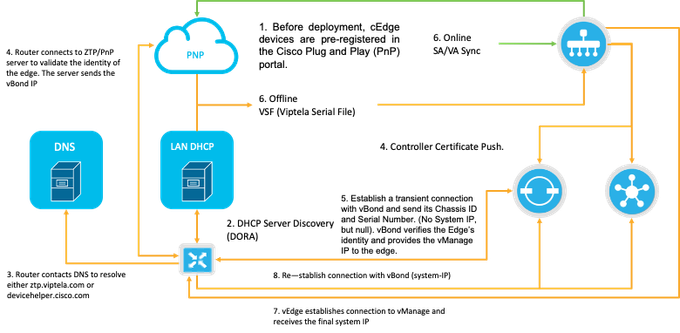
Fig. 1. PnP and WAN Edge device trust workflow diagram.
Secure Onboarding of the NFVIS Capable Device
Retrieve SN and Certificate Serial Number
The hardware based SUDI (Secure Unique Device Identifier) chip from NFVIS capable hardware is used to ensure only authorized devices can establish a secure TLS or DTLS control—plane tunnel to the SD-WAN Manager orchestrator. Collect the corresponding serial number using the support show chassis executive level command:
 C8300-UCPE-NFVIS# support show chassis
 Product Name             : C8300-UCPE-1N20
 Chassis Serial Num       : XXXXXXXXX
 Certificate Serial Num   : XXXXXXXXXXXXXXXXX
Add the Device to the PnP Portal
Navigate to https://software.cisco.com/software/pnp/devices and select the correct Smart Account and Virtual Account for your user or lab environment. (if multiple Smart Accounts coincide in name, you can distinguish them with the domain identifier).
If you or your user does not know which Smart Account (SA) / Virtual Account (VA) to work with, you can always search and existing/onboarded serial number in the “Device Search” text link to see to which SA/VA it belongs to.
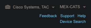
Fig. 2. SA/VA Selection and Device Search button.
Once the correct SA/VA is selected, click on ”Add Devices…”:
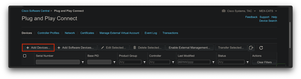
Fig. 3. "Add Devices..." Button to click for physical device registration.
For this particular case, onboard only 1 device, so a manual entry is enough:
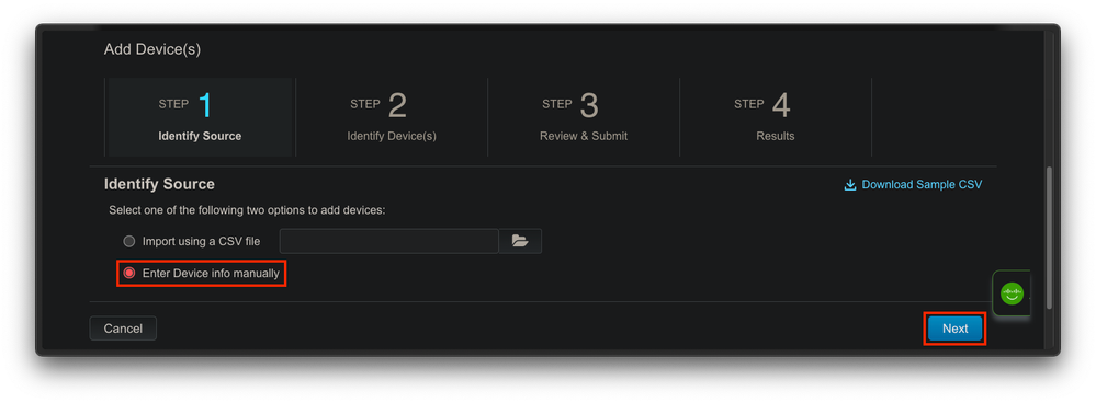
Fig. 4. "Add Devices..." alternative for device information input, manual (individual) or CSV (multiple).
For step 2, click on the “+ Identify Device…” button. A Form modal appears. Fill in the details with the information shown on the support show chassis output from NFVIS and select the corresponding vBond controller profile.
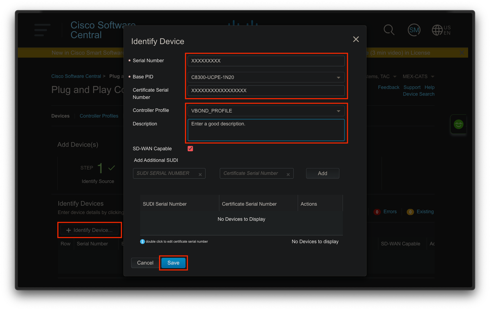
Fig. 5. Device Identification form.
Once it is saved, click on Next for Step 3 and finally on Submit for Step 4.
PnP In NFVIS
For more information about the diverse configuration setting for PnP within NFVIS, covering both automatic and static modes, please refer to the resource: NFVIS PnP Commands.
It is to be noted that PnP is enabled by default on all NFVIS versions.
vManage Synchronization with PnP
Online Mode
If vManage can reach internet and the PnP portal, you must be able to just perform a SA/VA sync. For this, navigate to Configuration > Devices, and click a text button that indicates Sync Smart Account. Credentials that are used for logging in to the Cisco Software Central is required. Ensure to send the certificate push to all controllers.
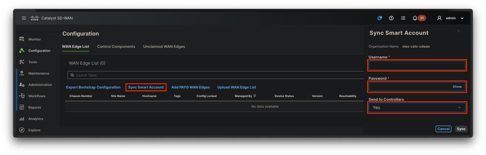
Fig. 6. WAN Edge Router update via SA/VA synchronization.
Offline Mode
If vManage is in a lab environment or does not have internet access, you can upload manually a provisioning file from PnP that must contain the SN that was added to the device list. This file is of type .viptela (Viptela Serial File), which can be obtained from the “Controller Profiles” tab:
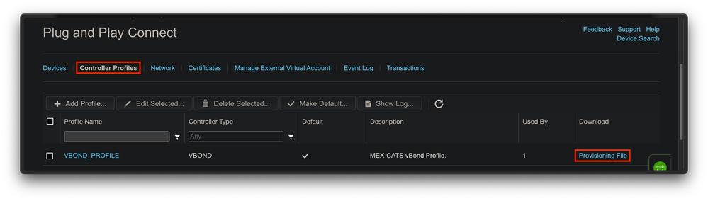
Fig. 7. Provisioning file download for CEdge WAN list update.
For the manual upload of the provisioning file, navigate to Configuration > Devices, and click a text button that indicates Upload WAN Edge List. A sidebar appears where you can drag and drop the respective file (if the Upload button does not highlight after these actions were made, click on Choose a file and search for the file manually within the pop-up file explorer window). Ensure to send the certificate push to all controllers.
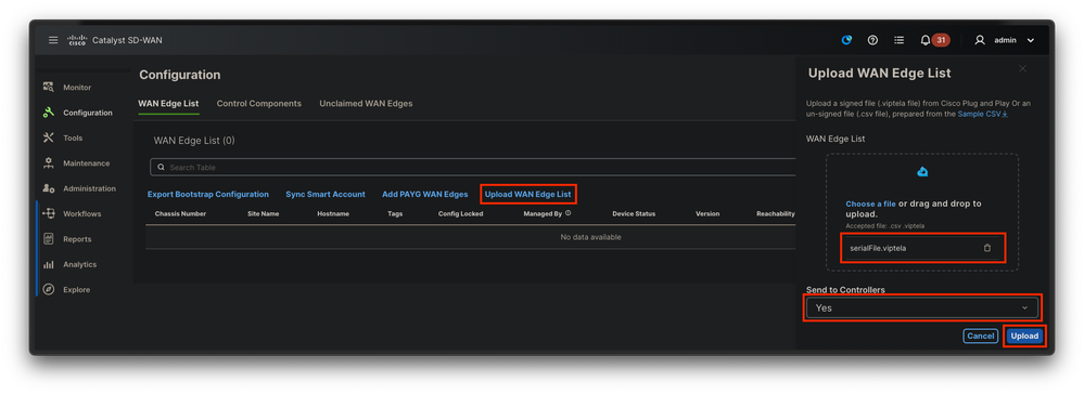
Fig. 8. WAN list update using the provisioning file (VSF, Viptela Serial File) downloaded from the PnP portal.
After completing either Online or Offline method, you must be able to see a device entry in the WAN Edge List table that correspods with the SN of the device registered in PnP:
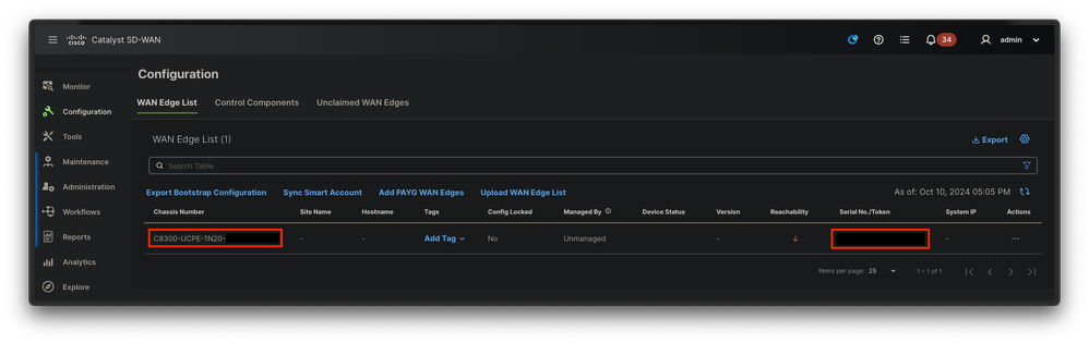
Fig. 9. 8300 device within the edge list.
NFVIS Automatic Onboarding and Control Connections
If NFVIS can resolve devicehelper.cisco.com (reach PnP through internet), onboarding is automatically performed. An onboarded NFVIS system automatically presents a viptela-system:system and vpn 0 configuration that contains basic controller information.
Starting from Cisco NFVIS Release 4.9.1, establishing a control connection to the management plane via the management port is supported. The management port needs to be reachable with SD-WAN Manager for a successful connection to the control plane.

Note: Every command containing the "system" keyword needs to be written as system:system. If the tab key is used for completion, it automatically adapts to this new standard.
C8300-UCPE-NFVIS# show running-config viptela-system:system
viptela-system:system
 admin-tech-on-failure
 no vrrp-advt-with-phymac
 sp-organization-name "Cisco Systems"
 organization-name "Cisco Systems"
 vbond <validator-ip> port 12346
 logging
  disk
   enable
  !
 !
 ntp
  parent
   no enable
   stratum 5
  exit
 !
!
VPN 0 is the pre-defined Transport VPN of the SD-WAN solution. It cannot be deleted nor modified. The purpose of this VPN is to enforce a separation between the WAN transport networks (the underlay) and network services (the overlay):
C8300-UCPE-NFVIS# show running-config vpn 0
vpn 0
 interface wan-br
  no shutdown
  tunnel-interface
   color gold
   allow-service all
   no allow-service bgp
   allow-service dhcp
   allow-service dns
   allow-service icmp
   no allow-service sshd
   no allow-service netconf
   no allow-service ntp
   no allow-service ospf
   no allow-service stun
   allow-service https
   encapsulation ipsec
  !
 !
!
Control connections are DTLS sessions established between different nodes (controllers and edge routers) of the SD-WAN fabric. Since NFVIS is not a routing platform in charge of routing decisions, it does not form control connections with the vSmarts. Out of the box, you can observe a “challenge” state for vManage:
C8300-UCPE-NFVIS# show control connection
                                                                                       PEER                                          PEER                                          CONTROLLER
PEER    PEER PEER            SITE       DOMAIN PEER                                    PRIV  PEER                                    PUB                                           GROUP
TYPE    PROT SYSTEM IP       ID         ID     PRIVATE IP                              PORT  PUBLIC IP                               PORT  ORGANIZATION            LOCAL COLOR     PROXY STATE UPTIME      ID
----------------------------------------------------------------------------------------------------------------------------------------------------------------------------------------
vbond   dtls 0.0.0.0         0          0      10.88.247.79                            12346 10.88.247.79                            12346 Cisco Systems           gold            NA    up     0:00:00:00 0
vmanage dtls 10.10.10.10     100        0      10.88.247.71                            12946 10.88.247.71                            12946 Cisco Systems           gold            No    challenge           0
This commonly indicates that there is no system-ip, and/or organization-name is wrongly or not configured at all. The PnP portal and vBond must establish the organization name and once the control-connection with vManage has been established. Otherwise, push this information within an NFV Config-Group (Supported starting from 20.14.1) with the respective system-ip and site-id in the template, or configure it statically within the viptela-system:system subconfiguration:
C8300-UCPE-NFVIS#(config)# viptela-system:system
C8300-UCPE-NFVIS#(config-viptela-system:system)# system-ip <custom-ip-format-id>
C8300-UCPE-NFVIS#(config-viptela-system:system)# site-id <site-id>
C8300-UCPE-NFVIS#(config-viptela-system:system)# organization-name <org-name>
C8300-UCPE-NFVIS#(config-viptela-system:system)# commit
Commit complete.
These items can be found within vManage:
- Organization Name: Administration > Settings > System > Organization Name
- Validator IP and Port: Administration > Settings > System > Validator
After the remaining configuration is entered within the viptela-system:system subconfiguration, you need active/established control connections.
C8300-UCPE-NFVIS# show control connections
                                                                                       PEER                                          PEER                                          CONTROLLER
PEER    PEER PEER            SITE       DOMAIN PEER                                    PRIV  PEER                                    PUB                                           GROUP
TYPE    PROT SYSTEM IP       ID         ID     PRIVATE IP                              PORT  PUBLIC IP                               PORT  ORGANIZATION            LOCAL COLOR     PROXY STATE UPTIME      ID
----------------------------------------------------------------------------------------------------------------------------------------------------------------------------------------
vbond   dtls 0.0.0.0         0          0      10.88.247.79                            12346 10.88.247.79                            12346 Cisco Systems           gold            NA    up     0:00:00:11 0
vmanage dtls 10.10.10.10     100        0      10.88.247.71                            12946 10.88.247.71                            12946 Cisco Systems           gold            No    up     0:00:00:06 0
Unmanaging NFVIS
In case you want to return NFVIS to its "Non-managed" state, you need to perform these actions:
- Remove the device entry from the PnP portal:
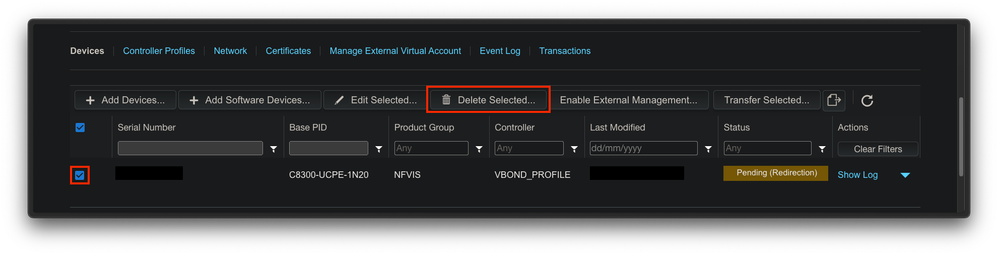
Fig. 10. 8300 device removal from the PnP portal.
2. Factory reset NFVIS.
C8300-UCPE-NFVIS# factory-default-reset all
3. Optional steps: Remove the device from the vManage Edge list:
3.1 Invalidate the device certificate.
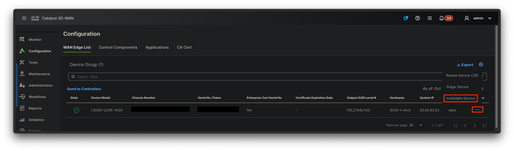
Fig. 11. 8300 certificate invalidation.
3.2 Delete the device from the WAN Edge list.
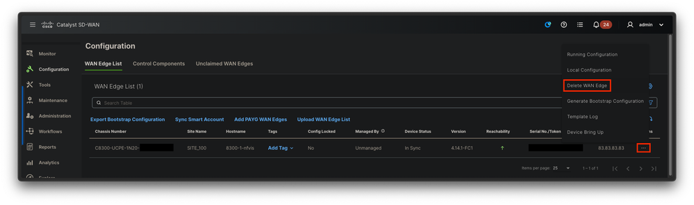
Fig. 12. 8300 removal from the WAN Edge list.
Fig. 8. WAN list update using the provisioning file (VSF, Viptela Serial File) downloaded from the PnP portal.
 Feedback