Introduction
This document describes how to configure boot from iSCSI using an Intel® X710T2LG 2x10 GbE RJ45 OCP 3.0 NIC Adapter and a UCS C225 M6 server.
Prerequisites
Requirements
Cisco recommends that you have knowledge of these topics:
- Cisco Integrated Management Controller (CIMC)® IP address configured.
- Basic knowledge on Internet Small Computer System Interface (iSCSI) configuration.
- Physical connectivity from the network adapter to the switch.
- Storage configuration parameters:
- LUN ID
- Port
- Initiator IQN
- Target IQN
- Initiator IP address
- Target IP address
- CHAP authentication information (if required)
Components Used
The information in this document is based on these software and hardware versions:
- Intel® X710T2LG 2x10 GbE RJ45 OCP 3.0 NIC Adapter
- Cisco® UCS C225 M6 server
- Microsoft® Windows® Server 2022 with iSCSI services enabled.
- Cisco® Catalyst 3560 switch
Previously, it was required to execute the Intel® Ethernet iSCSI Boot Flash Utility to configure the iSCSI settings. Now, the new Intel® adapters, have iSCSI configuration option available, directly on the server BIOS.
The information in this document was created from the devices in a specific lab environment. All of the devices used in this document started with a cleared (default) configuration. If your network is live, ensure that you understand the potential impact of any command.
Configuration Steps
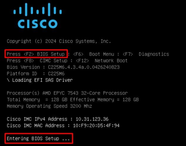
Step 1. Power On, or reboot the server. During the booting process, press F2 to access the server BIOS.
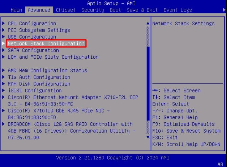
Step 2. In the server BIOS, select Network Stack Configuration option:
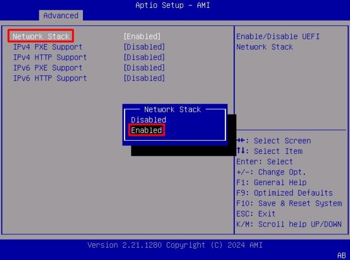
Step 3. Select Enabled:
Step 4. Once the network stack is enabled, select the network adapter to use for iSCSI boot.
In this example, the Cisco® X710T2LG 2x10 GbE RJ45 Adapter is used:
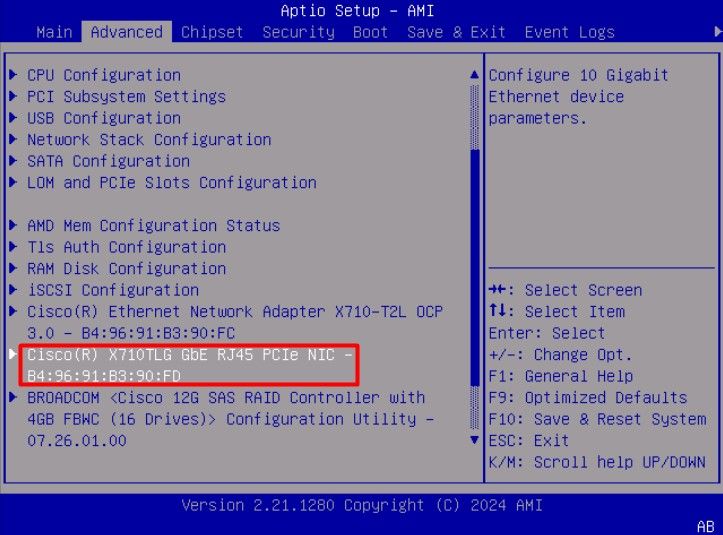
Step 5. Inside the network adapter option, validate the Link Status is Connected.
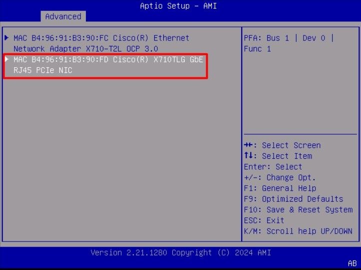
Note: Take note of the port MAC address, as it is useful for identification purposes.
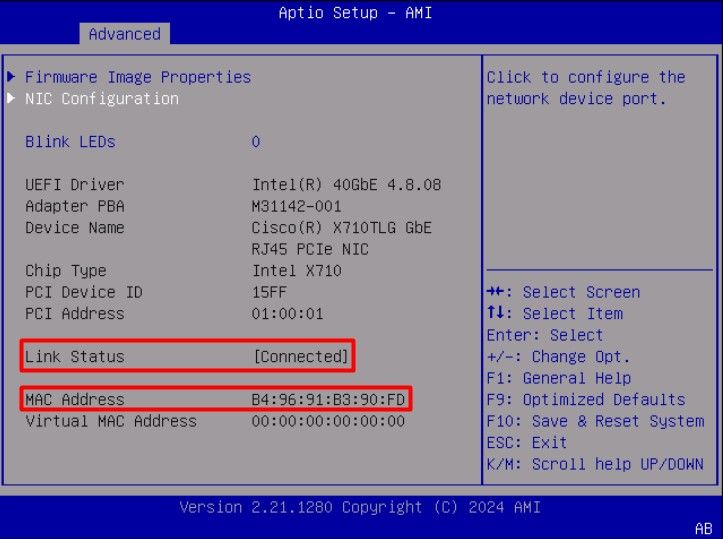
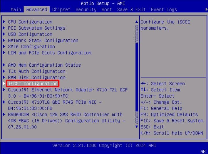
Step 6. Go back to the main menu, and select the iSCSI Configuration option:
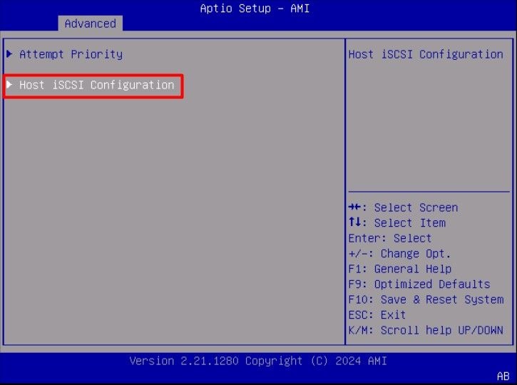
Step 7. Select Host iSCSI Configuration option:
Step 8. Add the ISCSI Qualified Name (IQN), for the initiator.
The iSCSI Qualified Name (IQN) format takes the form iqn.yyyy-mm.naming-authority:unique name.
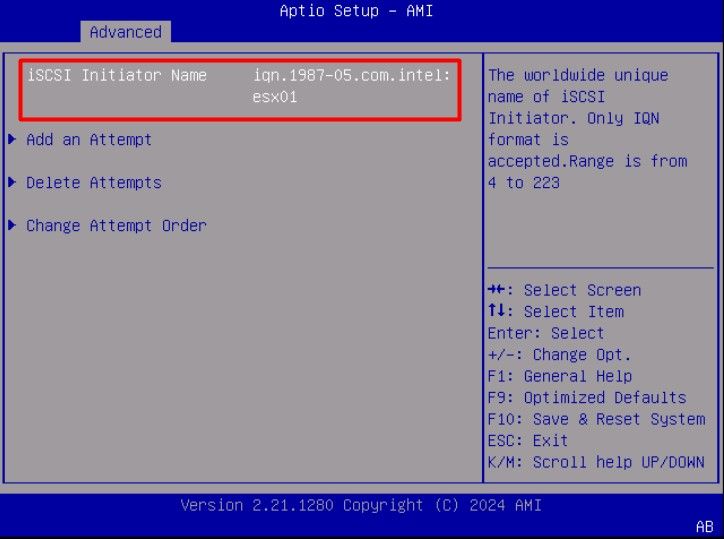
Step 9.Select the Add an Attempt option:
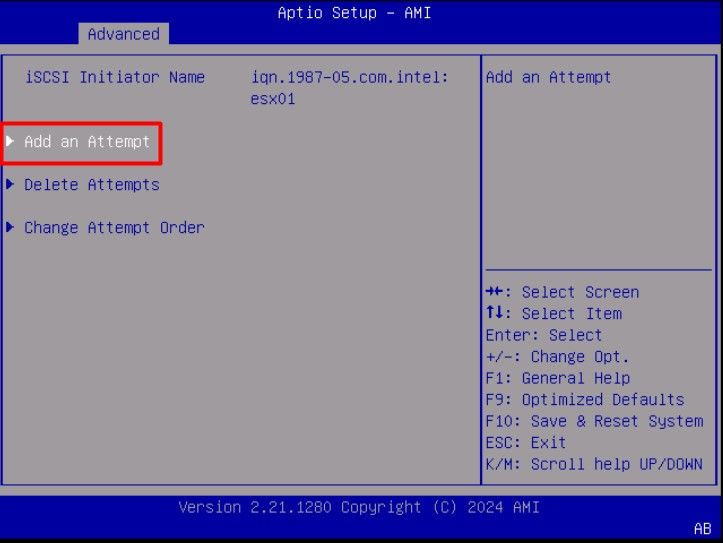
Step 10. Select the correct adapter, to configure the iSCSI settings. You can verify the adapter with the mac address that was registered on Step 5.
Step 11. Configure the iSCSI settings:
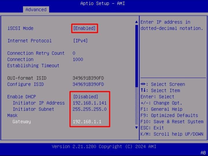
The values for this example are:
- iSCSI Mode: Enabled
- Internet Protocol: IPv4
- Connection Retry Count: 0 (Default)
- Connection Establishment Timeout: 1000 (milliseconds)
- OUI-Format ISID: (Default)
- Configure ISID: (Default)
- Enable DHCP: Disabled
- Initiator IP Address: 192.168.1.141
- Initiator Subnet Mask: 255.255.255.0
- Gateway: 192.168.1.1
Step 12. Configure the Target information:
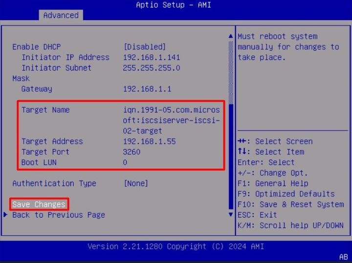
The values for this example are:
- Target Name: (Target IQN for the storage)
- Target Address: 192.168.1.55
- Target Port: 3260 (iSCSI default port)
- Boot Lun in hexadecimal format: 0
- Authentication Type: None
Select Save Changes.
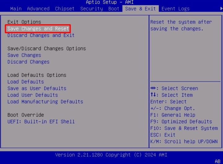
Step 13. Select the Save & Exit Menu, then select Save Changes and Reset:
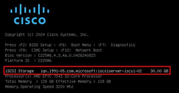
Step 14. Once the server boots, the iSCSI storage information is displayed during the boot process:
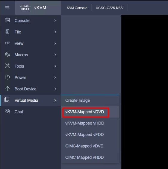
Step 15. Map an OS ISO using the Virtual Media > vKVM-Mapped DVD option:
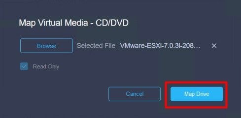
Step 16. Select Map Drive:
Step 17. Once the ISO is mapped, boot from it using the F6 Menu. Wait for the installer to load. Once the installer displays the storage options to install, the remote iSCSI storage is visible:
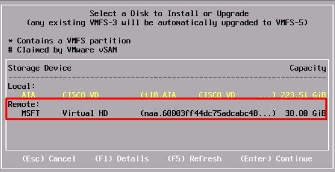
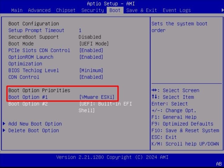
Step 18. Continue the installation process using the remote storage. Once it finishes, reboot the server and press F2 to enter the server BIOS settings. In the BIOS settings, select the Boot Menu and move the option VMware® ESXi to the Boot Option # 1:
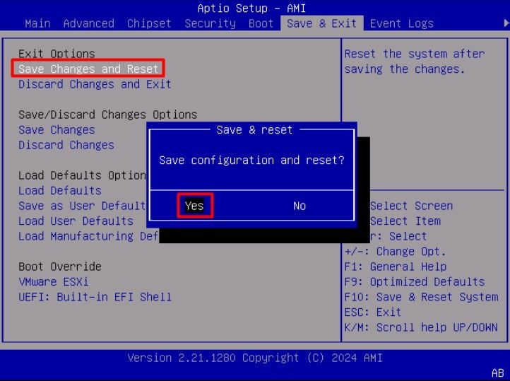
Step 19. Navigate to the Save & Exit menu, and select Save Changes and Reset option:
Verify
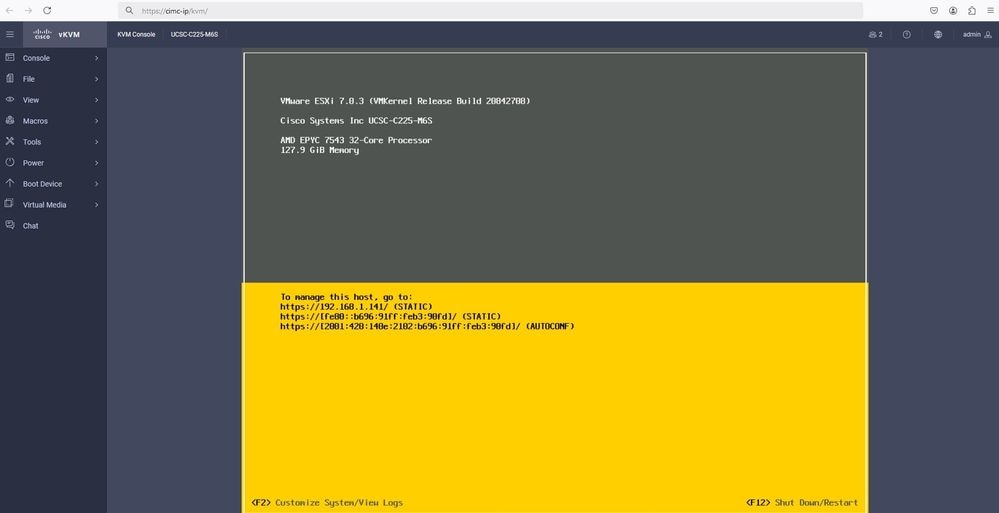
The server successfully boots to the VMware® ESXi OS:
Troubleshooting
- Verify the IQN for the Initiator and Target to avoid any misconfiguration.
- Verify the switch port configuration, as the NIC Adapter does not support any VLAN tagging.
- Verify the adapter port mac address is learned on the correct port on the switch.
switch#show mac address-table address b496.91b3.90fd
            Mac Address Table
-------------------------------------------
Vlan  Mac Address  Type    Ports
---- ----------- -------- -----
10   b496.91b3.90fd DYNAMIC Te1/0/45
Total Mac Addresses for this criterion: 1
Verify the iSCSI negotiation with a packet capture leveraging the Embedded Packet Capture (EPC) feature in Cisco IOS® software.
Example:
switch#monitor capture ISCSI buffer size 100 circular interface TenGigabitEthernet1/0/45 both match any
switch#monitor capture ISCSI start --> This command starts the capture
switch# monitor capture ISCSI stop --> Stop the capture, once the server has attempted to boot from the Intel® NIC Adapter.
switch#show monitor capture ISCSI buffer brief --> This command shows the capture content
Starting the packet display ........ Press Ctrl + Shift + 6 to exit
...
21 0.000285 192.168.1.141 -> 192.168.1.55 iSCSI 114 NOP Out
22 0.000299 192.168.1.55 -> 192.168.1.141 iSCSI 118 NOP In
23 0.000313 192.168.1.55 -> 192.168.1.141 iSCSI 118 [TCP Retransmission] NOP In
24 0.000327 192.168.1.141 -> 192.168.1.55 TCP 66 57954 > iscsi-target [ACK] Seq=49 Ack=49 Win=514 Len=0 TSval=2153290808 TSecr=1148234211
25 0.000341 192.168.1.141 -> 192.168.1.55 TCP 1514 [TCP segment of a reassembled PDU]
26 0.000357 192.168.1.141 -> 192.168.1.55 TCP 1514 [TCP segment of a reassembled PDU]
27 0.000382 192.168.1.141 -> 192.168.1.55 iSCSI 1514 SCSI: Write(10) LUN: 0x00 (LBA: 0x0105f758, Len: 8)SCSI: Data Out LUN: 0x00 (Write(10) Request Data)
28 0.000399 192.168.1.141 -> 192.168.1.55 TCP 102 [TCP segment of a reassembled PDU]
29 0.000413 192.168.1.55 -> 192.168.1.141 TCP 70 iscsi-target > 57954 [ACK] Seq=49 Ack=4429 Win=8195 Len=0 TSval=1148234577 TSecr=2153290836
30 0.000427 192.168.1.141 -> 192.168.1.55 TCP 1514 [TCP segment of a reassembled PDU]
31 0.000448 192.168.1.141 -> 192.168.1.55 TCP 1514 [TCP segment of a reassembled PDU]
32 0.000464 192.168.1.141 -> 192.168.1.55 iSCSI 1078 SCSI: Write(10) LUN: 0x00 (LBA: 0x0105f548, Len: 8)SCSI: Data Out LUN: 0x00 (Write(10) Request Data)
33 0.000480 192.168.1.55 -> 192.168.1.141 TCP 70 iscsi-target > 57954 [ACK] Seq=49 Ack=8337 Win=8195 Len=0 TSval=1148234578 TSecr=2153290837
34 0.000494 192.168.1.55 -> 192.168.1.141 iSCSI 118 SCSI: Response LUN: 0x00 (Write(10)) (Good)
35 0.000508 192.168.1.55 -> 192.168.1.141 iSCSI 118 SCSI: Response LUN: 0x00 (Write(10)) (Good)
Verify the LUN ID is correct in hexadecimal format. In the example below, the error message "SCSI transfer limited due to allocation_length too small" is displayed within the iSCSI packet capture as the LUN ID information is incorrect.
 ISCSI error
For RJ45 NIC adapters, it is recommended to use at least a Cat6 UTP cable, and connect to 10 GbE ports.
Related Information


 Feedback