- Preface
- Cisco Remote-PHY Solution Overview
- Cisco Remote-PHY Solution Deployment
- Installing the Cisco Remote-PHY Solution
- Configuring the Cisco Remote-PHY Solution
- Upgrading the Cisco Remote-PHY Solution
- Maintaining and Monitoring the Cisco Remote-PHY Solution
- Troubleshooting the Cisco Remote-PHY Solution
Cisco Remote-PHY
Solution Overview
Introduction
Driven by market evolution towards triple-play services, cable operators in emerging markets are seeking standardized and digital fiber-based solutions for economical and future proof access technologies. Much of the demand is driven by the need to provide higher bandwidth packet transport for Internet connectivity, video and voice services.
Data Over Cable Systems Interface Standard (DOCSIS®) is a standardized technology for services over cable and thus has strong interoperability between system providers. It also provides robust Quality of Service (QoS) methods, ensuring packet delivery during periods of network congestion. Traditionally, DOCSIS runs on linear fiber (or HFC) to provide service and is not naturally applicable for digital fiber. Cisco has bridged the gap by introducing a new access technology called the Remote-PHY.
Existing Architecture
In the emerging markets, most triple-play consumers live in multi-tenant buildings (referred to as Multi Dwelling Units or MDU) with the number of residents usually being less than 500 residents per building or cluster. These buildings are typically served by fiber with one of several “final 100 meter” technologies installed in the buildings. These technologies include fiber, twisted pair, Ethernet, and coaxial. Cable operators have access to the cable in the building and use this cable for their services. Several technologies exist for enabling two-way services over cable. These include a number of proprietary and vendor-specific methods. However, a standards-based approach to using cable is typically preferred by operators, since this ensures vendor interoperability.
Need for the Cisco Remote-PHY Solution
DOCSIS and EuroDOCSIS are standards that define two-way operation over a cable network. DOCSIS provides the necessary Quality of Service (QoS) tools for ensuring voice call connectivity during periods of network congestion that are anticipated in triple-play networks. DOCSIS is a robust and mature technology for voice, video, and IP video services.
The Cisco Remote-PHY solution leverages existing IP technologies and deploys DOCSIS in remote field over digital fiber to enable two-way services over cable.
Benefits
-
Simple and low cost PON transmission as opposed to costly HFC transformation.
-
Reduced investment cost including capital and operational expenditure.
-
Low-cost yet highly stable Cisco CMC (includes only the PHY layer).
-
Reduced CMTS hardware complexity.
-
No restriction on Converged Interconnect Network (CIN) network.
-
Futureproof architecture. Easy to migrate as the hardware and control functions are on separate layers.
-
End-to-end QoS assurance provided by DOCSIS.
-
Support for all DOCSIS services.
-
Support for existing DOCSIS network provisioning system.
-
High access bandwidth.
-
With deep fiber, the optical noise contribution to SNR is eliminated. As a result, the remote QAM modulator runs at higher orders of modulation as compared to a centralized QAM modulator.
Architecture Overview
Modular Headend Architecture version 2 (MHAv2) is a set of specifications for the Cisco Remote-PHY solution. It uses digital fiber compatible baseband networking technology, such as Ethernet, EPON, or GPON to drive the fiber portion of the HFC plant. The coaxial portion of the plant remains the same. In MHAv2, the upstream PHY is located on the remote side and acts as the remote PHY system together with the downstream PHY. This is a device called the Coaxial Media Converter (CMC), which connects the digital fiber and the coaxial portions of the plant together. The CMC resides near or in buildings and has both RFI and Gigabit Ethernet interfaces. The CMC provides layer 1 PHY (downstream and upstream PHY) functionality, layer 2 MAC functionality, and layer 3 tunneling and forwarding support. The CMTS remains unchanged with the exception of the upstream PHY being moved to the remote CMC. The Cisco uBR-MC3GX60V-RPHY line card installed in the Cisco CMTS does not have the RFI interfaces for downstream and upstream, instead, it has Gigabit Ethernet interfaces for both downstream and upstream.
Protocols that form this architecture include:
-
Downstream External PHY Interface Decapsulation—Downstream External PHY Interface (DEPI) is a L2TPv3-based protocol defined for downstream DOCSIS MAC management and data packets decapsulation. It is unidirectional, that is, from CMTS to CMC.
DEPI supports: -
Upstream External PHY Interface Encapsulation—Upstream External PHY Interface (UEPI) is a L2TPv3-based protocol defined for upstream DOCSIS MAC management and data packets encapsulation. It is unidirectional, that is, from CMC to CMTS.
UEPI: -
GCP—Generic Control Protocol, sets up a control plane tunnel over a generic transport protocol such as TCP or UDP. GCP is used to program CMC upstream PHY parameters from the CMTS. It is also used to control the CMC.
GCP supports:
Cisco Cable Modem Termination System
The Cisco uBR10012 universal broadband router acts as the Cable Modem Termination System (CMTS) core for the Cisco Remote-PHY architecture.
Cisco Coaxial Media Converter
The Cisco Coaxial Media Converter (CMC) acts as the edge QAM in the Cisco Remote-PHY architecture. It is located between the Cisco CMTS and the cable modem, and controlled by the Cisco CMTS. The Cisco CMC has network interfaces on one side connecting to the fiber (digital and linear) portion of the Hybrid Fiber Coaxial (HFC) plant, and RF interfaces on the other side connecting to the coaxial portion of the HFC plant. The Cisco CMC can be mounted either on a wall or strand (aerial installation). The RF output of the Cisco CMC can be combined with other services, such as, analog or digital video services. The Cisco CMC uses the linux operating system. Most of the Cisco CMC configurations are performed on the Cisco CMTS.
The Cisco CMC terminates the Ethernet Passive Optical Network (EPON) protocol with an embedded Optical Network Unit (ONU) and originates the DOCSIS protocol using the DOCSIS MAC and PHY layer technology used in the Cisco CMTS. The Cisco CMC has built-in downstream PHY and upstream PHY, and a small FPGA for DEPI decapsulation and UEPI encapsulation. The Cisco CMC supports up to 16 downstream QAM channels and four upstream channels.
For more information on the Cisco CMC product identifiers (PIDs), see Product Identifiers.
The Cisco CMC has a hinged lid to allow access to the internal electrical and optical components. It also has a waterproof rubber on the base and an EMI gasket on the lid to seal the equipment. The table below lists the dimensions of the Cisco CMC
|
Unit |
Value |
|---|---|
|
Depth |
12.48 in (31.7 cm) |
|
Width |
15.86 in (40.3 cm) |
|
Height |
6.69 in (17 cm) |
|
Weight |
26 lbs (11.8 kg) |
The figures below show the external housing dimensions of the Cisco CMC.

Ports on the Cisco CMC
The Cisco CMC has the following ports or external interfaces:
-
One RF input port (CATV IN)
-
Four RF output ports
-
Two SFP ports (1+1 redundancy)
-
Two RJ-45 Gigabit Ethernet ports (1+1 redundancy)
-
One power input port
-
Two fiber input ports
-
One console port
The figure below shows the ports on the external housing of the Cisco CMC.

| 1 | CATV input (RF input port) | 4 | RJ-45 port |
| 2 | Power port | 5 | RF output ports |
| 3 | Fiber input ports | — |
The figure below shows the ports that are located inside the Cisco CMC.

| 1 | RJ-45 Gigabit Ethernet ports | 3 | SFP ports |
| 2 | Console port | — |
The Cisco CMC contains the following modules:
RF I/O Module
The RF I/O module on the Cisco CMC can split the CATV input or one downstream into four RF outputs on the downstream. The RF I/O module can also combine four RF outputs into one upstream. The figure below shows the RF I/O module on the Cisco CMC.

| 1 | Forward equalizers | 7 | Reverse output attenuator pads |
| 2 | Reverse test point | 8 | Forward pads |
| 3 | Reverse input attenuator pad | 9 | Downstream RF input port |
| 4 | Forward test point | 10 | Upstream RF output port |
| 5 | Signal directors | 11 | RF input (CATV IN) port |
| 6 | RF output ports | 12 | Base cover |
The RF I/O module consists of the following components. Some of the components on the Cisco CMC (attenuator pads, equalizers, and signal directors) can be removed and replaced with the same components of different values during the setup procedures.
|
Component |
Description |
|---|---|
|
RF input port |
The Cisco CMC has one RF input port, which provides the CATV input from an external node or amplifier. |
|
RF output ports |
The Cisco CMC has four RF output ports, which are used for forward signal output and reverse signal input. |
|
Test points |
The Cisco CMC has three test points, which are used for monitoring the signals. It consists of the following types of test points: |
|
Downstream RF input port |
The Cisco CMC has one downstream RF input port from the motherboard module. |
|
Upstream RF output port |
The Cisco CMC has one upstream RF output port to the motherboard module. |
|
Equalizers |
The Cisco CMC has two forward equalizers. |
|
Signal directors |
A signal director routes or splits the RF input signal to the RF output ports. The Cisco CMC has two signal directors. The Cisco CMC supports the following components as a signal director: |
|
Attenuator pads |
The Cisco CMC has the following attenuator pads: |
Block Diagram
The figure below shows the block diagram of the Cisco CMC RF I/O module:

Motherboard Module
The figure below shows the motherboard module of the Cisco CMC:

| 1 | RJ-45 Gigabit Ethernet ports | 6 | Upstream RF input port |
| 2 | SFP ports | 7 | Power connector |
| 3 | Reset button | 8 | FRx and RF I/O connector |
| 4 | LEDs | 9 | Console port and golden image jumper |
| 5 | Downstream RF output port | — |
The Cisco CMC motherboard module consists of the following components:
|
Component |
Description |
|---|---|
|
RJ-45 ports |
The Cisco CMC has two RJ-45 Gigabit Ethernet ports, which are used to connect it to the switch or OLT. The Cisco CMC supports 1+1 redundancy for the RJ-45 Gigabit Ethernet ports. |
|
SFP ports |
The Cisco CMC has two SFP ports, which are used to connect it to the switch or OLT. The Cisco CMC supports 1+1 redundancy for the SFP ports. The Cisco CMC supports Gigabit Ethernet SFP and EPON SFP. |
|
Reset button |
The Cisco CMC has a reset button, which is used to power-cycle the motherboard module (that is, power it down and then power it up). |
|
LEDs |
The Cisco CMC has the following LEDs on the motherboard module for monitoring the Cisco CMC: |
|
Console port |
The Cisco CMC has one console port, which is used to connect it to a PC. This port has three pins. You must use a 3-pin connector to connect to this port. |
|
Golden image jumper |
The golden image jumper has three pins, two ground-pins and one golden image-pin. When the golden image-pin is shorted with the ground-pin, the Cisco CMC boots with the golden image. |
|
Power connector |
The Cisco CMC has an 8-pin 12 V power connector, which provides power to the motherboard module. |
|
FRx and RF I/O connector |
The Cisco CMC has one FRx and RF I/O connector, which provides the Universal Asynchronous Receiver and Transmitter (UART) signals to the FRx. |
|
Downstream RF output port |
The Cisco CMC has one downstream RF output port, which is connected to the downstream RF input port on the RF I/O module through a connector. |
|
Upstream RF input port |
The Cisco CMC has one upstream RF input port, which is connected to the upstream RF output port on the RF I/O module through a connector. |
Power Supply Unit
The Power Supply Unit (PSU) provides power to the Cisco CMC. The Cisco CMC is available in the following variants of the PSUs:
Cisco CMC With the 220VAC PSU
The Cisco CMC with 220VAC power supply does not support the pass-through capability. The figure below shows the rating label for the Cisco CMC with the 220VAC PSU:

Cisco CMC With the 60VAC PSU
The Cisco CMC with 60VAC power supply supports the pass-through capability. The figure below shows the rating label for the Cisco CMC with the 60VAC PSU:

FRx
The Forward Optical Receiver Module (FRx) is a 52 to 1002 MHz forward path optical to electrical conversion module. It receives the intensity modulated optical signals incident to the optical connector and provides the corresponding electrical signals as output. The figure below shows the FRx used for the Cisco CMC:

| 1 | Optical input port | 4 | Power port |
| 2 | LEDs | 5 | RF output port |
| 3 | Universal Asynchronous Receiver and Transmitter (UART) port | — |
The FRx consists of the following components:
|
Component |
Description |
|---|---|
|
Optical input port |
This port is used for providing the input optical signal to the FRx. This port is connected to the SC/APC adapter on the Cisco CMC. |
|
Power port |
This port is used for providing power input to the FRx. The FRx supports 12.6 V and 5 V power inputs. Use a 3-pin connector to provide power to the FRx from the power supply unit. |
|
LEDs |
LEDs are used for monitoring if the optical input level and communication are operational on the FRx. The FRx contains two LEDs: |
|
RF output port |
This port is used for providing the RF output signal to the Cisco CMC. |
|
UART port |
This port is used for connecting the control cable from the Cisco CMC to the FRx. Use a 4-pin connector for the UART port. |
Cisco uBR-MC3GX60V-RPHY Line Card
The Cisco uBR-MC3GX60V-RPHY line card transmits and receives RF signals between the subscriber and headend over the hybrid fiber-coaxial (HFC) system and is DOCSIS 3.0-compliant. The Cisco uBR-MC3GX60V-RPHY line card is designed specifically for the Cisco uBR10012 router and conforms to the Modular CMTS (M-CMTS) architecture.
The Cisco uBR-MC3GX60V-RPHY line card is installed in the CMTS and connected to the Cisco CMC via the EPON, GPON, or Metro Ethernet. The Cisco uBR-MC3GX60V-RPHY line card supports both downstream and upstream traffic. The Cisco uBR-MC3GX60V-RPHY line card has three pairs of Gigabit Ethernet (GE) ports as external interfaces and 1 + 1 redundancy for the Metro Ethernet ports. Both the downstream and upstream traffic share the same ports.
The Cisco uBR-MC3GX60V-RPHY line card supports 24 downstream RF channels and 20 upstream RF channels per Gigabit Ethernet port. Hence, a total of 72 downstream RF channels and 60 upstream RF channels across the Gigabit Ethernet ports.
|
Unit |
Dimensions |
|---|---|
|
Width |
21.65 in (55 cm ) |
|
Height |
14.17 in (3.6 cm) |
|
Depth |
172.44 in (43.8 cm) |
|
Weight |
12.99 lbs (5.895 kg) |

| 1 |
Captive Screw |
2 |
Front panel display (FPD) |
Cisco uBR-MC3GX60V-RPHY line card contains the following components:
-
LEDs—The LEDs are located on the front panel of the line card and indicates the status of the line card.
The line card has the following LEDs for monitoring its status:
-
Gigabit Ethernet ports—The Cisco uBR-MC3GX60V-RPHY line card has three pairs of Gigabit Ethernet ports as external interfaces and the SFP modules are inserted into the Gigabit Ethernet ports to connect to a switch or an OLT. For more information on SFP modules, see SFP Modules for the Cisco uBR-MC3GX60V-RPHY Line Card.
-
Front panel display—The Front panel four-character alphanumeric display shows the licensing status information of the US and DS channels.
Software License for the Cisco uBR-MC3GX60V-RPHY Line Card
The Cisco uBR-MC3GX60V-RPHY line card requires software licensing to restrict the number of US and DS channels used. The Cisco uBR-MC3GX60V-RPHY line card supports 16 to 60 US channels and 16 to 72 DS channels.
The Cisco uBR-MC3GX60V-RPHY line card uses a smart chip authentication device to prevent counterfeit line cards. A digital signature is embedded in the line card, and the Public Key Encryption techniques are used to verify the authenticity of the digital signature. The software licenses are physically stored on the line cards. You cannot transfer the software licenses between different types of line cards.
The front panel four-character alphanumeric display on the line card shows the licensing status information of the US and DS channels. The first two characters of the display represent the DS license count and the last two characters represent the US license count.
The table below shows some of the US and DS channel combinations supported on the Cisco uBR-MC3GX60V-RPHY line card and their corresponding license type.
|
Front Panel Display |
Downstream |
Upstream |
|---|---|---|
|
3G60 |
72 |
60 |
|
2G40 |
48 |
40 |
|
1G20 |
24 |
20 |
|
3314 |
33 |
14 |
Compatibility Matrix for the Cisco uBR-MC3GX60V-RPHY Line Card
|
Cisco CMTS Platform |
Processor Engine |
Cisco IOS Release |
|---|---|---|
|
Cisco uBR10012 router |
PRE4 |
12.2(33)CX and later releases |
|
Cisco uBR10012 router |
PRE5 |
12.2(33)CX and later releases |
Onboard Failure Logging
The Onboard Failure Logging (OBFL) feature enables the storage and collection of critical failure information in the nonvolatile memory of a Field Replaceable Unit (FRU), like a route processor (RP) or line card. The Cisco uBR10000 series universal broadband router supports OBFL on PRE4, the Cisco SIP-600 jacket card, Cisco uBR-MC3GX60V-RPHY, Cisco uBR-MC3GX60V, Cisco UBR-MC20X20V, and the Cisco uBR-MC5X20H line cards.
The data stored through OBFL assists in understanding and debugging the field failures upon Return Material Authorization (RMA) of a RP or line card at repair and failure analysis sites. OBFL records operating temperatures, voltages, hardware uptime, and any other important events that assist board diagnosis in case of hardware failures.
For more information about the feature, see Onboard Failure Logging.
 Note | The sample output provided in the Onboard Failure Logging guide may vary slightly for the Cisco CMTS routers. |
SFP Modules for the Cisco uBR-MC3GX60V-RPHY Line Card
The Small Form-factor Pluggable (SFP) modules are I/O devices that are inserted into the Gigbit Ethernet ports, linking the ports to an OLT or a switch through a network cable.
The table below lists the SFP modules that are supported on the Cisco uBR-MC3GX60V-RPHY line card. The only restriction is that each SFP module must match the wavelength specifications on the other end of the cable and the cable must meet the stipulated cable length range for reliable communications.
|
SFP Part Number |
SFP Module |
Description |
Supported Connector | Supported Cable Type |
|---|---|---|---|---|
|
SFP-GE-T |
RJ-45 copper (1000BASE-T) |
Provides full-duplex Gigbit Ethernet connectivity to high-end workstations, and between wiring closets over an existing copper network infrastructure. |
RJ-45 connector |
Copper |
|
GLC-SX-MMD |
Short wavelength (1000BASE-SX) |
Contains a Class 1 laser of 850 nm for 1000BASE-SX (short-wavelength) applications. |
LC Fiber-Optic connector |
Multimode fiber (MMF)1 |
|
GLC-LH-SMD |
Long wavelength/long haul (1000BASE-LX/LH) |
Contains a Class 1 laser of 1310 nm for 1000BASE-LX/LH (long-wavelength) applications. |
LC Fiber-Optic connector |
Single-mode fiber (SMF) Multimode fiber (MMF) |
|
GLC-ZX-SMD2 |
Extended distance (1000BASE-ZX) |
Contains a Class 1 laser of 1550 nm for 1000BASE-ZX (extended-wavelength) applications. |
LC Fiber-Optic connector |
Single-mode fiber (SMF) |
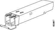
The SFP modules can have three types of latches to secure it in a port socket. Determine the type of latch your SFP module uses before you complete the installation and removal procedures.
|
SFP Module |
Description |
Illustration |
|---|---|---|
|
Bale clasp SFP module |
The bale clasp SFP module has a clasp that you use to remove or install the SFP module in a Gigbit Ethernet port. |
 |
|
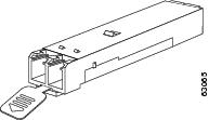
Mylar tab SFP module |
The mylar tab SFP module has a tab that you pull to remove the module from a Gigbit Ethernet port. |
 |
|
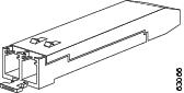
Actuator button SFP module |
The actuator button SFP module includes a button that you push to remove the SFP module from a Gigbit Ethernet port. |
 |
For more information on SFP modules, see Cisco Small Form-Factor Pluggable Modules for Gigabit Ethernet Applications Data Sheet.
Optical Line Terminal
Optical Line Terminal (OLT) equipment supports:
Product Identifiers
The tables below list the component product identifiers (PID) for the Cisco CMC and the Cisco uBR-MC3GX60V-RPHY line card.
|
Component |
PID |
|---|---|
|
Cisco CMC |
|
|
Cisco CMC, 60 V, 6 downstream (DS) and 4 upstream (US) channels, 42/54MHz |
CMC-L-L-16X4 |
|
Cisco CMC, 60 V, 16 DS and 4 US channels, 65/87MHz |
CMC-L-M-16x4 |
|
Cisco CMC, 60 V, 16 DS and 4 US channels, 42/54MHz, with node |
CMC-L-L-16X4-N |
|
Cisco CMC, 60 V,16 DS and 4 US channels, 65/87MHz, with node |
CMC-L-M-16x4-N |
|
Cisco CMC, 110/220 V, 16 DS and 4 US channels, 42/54 MHz, US power cord |
CMC-M-L-16X4-US |
|
Cisco CMC, 110/220 V, 16 DS and 4 US channels, 42/54 MHz, JP power cord |
CMC-M-L-16X4-JP |
|
Cisco CMC, 110/220 V, 16 DS and 4 US channels, 42/54 MHz, EU power cord |
CMC-M-L-16X4-EU |
|
Cisco CMC, 110/220 V, 16 DS and 4 US channels, 42/54 MHz, UK power cord |
CMC-M-L-16X4-UK |
|
Cisco CMC, 110/220 V, 16 DS and 4 US channels, 42/54 MHz, India power cord |
CMC-M-L-16X4-ID |
|
Cisco CMC, 110/220 V, 16 DS and 4 US channels, 65/87 MHz, CH power cord |
CMC-M-M-16x4-CH |
|
Cisco CMC, 110/220 V, 16 DS and 4 US channels, 65/87 MHz, JP power cord |
CMC-M-M-16x4-JP |
|
Cisco CMC, 110/220 V, 16 DS and 4 US channels, 65/87 MHz, US power cord |
CMC-M-M-16x4-US |
|
Cisco CMC, 110/220 V, 16 DS and 4 US channels, 65/87 MHz, EU power cord |
CMC-M-M-16x4-EU |
|
Cisco CMC, 110/220 V, 16 DS and 4 US channels, 65/87 MHz, UK power cord |
CMC-M-M-16x4-UK |
|
Cisco CMC, 110/220 V, 16 DS and 4 US channels, 65/87 MHz, AU power cord |
CMC-M-M-16x4-AU |
|
Cisco CMC, 110/220 V, 16 DS and 4 US channels, 42/54 MHz, US power cord, with node |
CMC-M-L-16X4-USN |
|
Cisco CMC, 110/220 V, 16 DS and 4 US channels, 42/54 MHz, EU power cord, with node |
CMC-M-L-16X4-EUN |
|
Cisco CMC, 110/220 V, 16 DS and 4 US channels, 42/54 MHz, JP power cord, with node |
CMC-M-L-16X4-JPN |
|
Cisco CMC, 110/220 V, 16 DS and 4 US channels, 42/54 MHz, UK power cord, with node |
CMC-M-L-16X4-UKN |
|
Cisco CMC, 110/220 V, 16 DS and 4 US channels, 42/54 MHz, ID power cord, with node |
CMC-M-L-16X4-IDN |
|
Cisco CMC, 110/220 V, 16 DS and 4 US channels, 65/87 MHz, CH power cord, with node |
CMC-M-M-16x4-CHN |
|
Cisco CMC, 110/220 V, 16 DS and 4 US channels, 65/87 MHz, JP power cord, with node |
CMC-M-M-16x4-JPN |
|
Cisco CMC, 110/220 V,16 DS 4 US channels, 65/87 MHz, US power cord, with node |
CMC-M-M-16x4-USN |
|
Cisco CMC, 110/220 V, 16 DS and 4 US channels, 65/87 MHz, EU power cord, with node |
CMC-M-M-16x4-EUN |
|
Cisco CMC, 110/220 V, 16 DS and 4 US channels, 65/87 MHz, UK power cord, with node |
CMC-M-M-16x4-UKN |
|
Cisco CMC, 110/220 V, 16 DS and 4 US channels, 65/87 MHz, AU power cord, with node |
CMC-M-M-16x4-AUN |
|
Cisco CMC, 110/220 V, 16 DS and 4 US channels, 65/87 MHz, ID power cord, with node |
CMC-M-M-16x4-IDN |
|
Gigabit Ethernet SFP |
|
|
1000BASE-BX10 10KM distance |
GLC-BX-U |
|
1000BASE-SX 550M distance; rugged SFP |
GLC-SX-MM-RGD |
|
1000BASE-LX/LH 10KM distance; rugged SFP |
GLC-LX-SM-RGD |
|
1000BASE-EX long-wavelength; with DOM |
GLC-EX-SMD |
|
1000BASE-ZX 80KM distance; rugged SFP |
GLC-ZX-SM-RGD |
|
Ethernet Passive Optical Network (EPON) SFP Optical Network Unit (ONU) |
|
|
EPON ONU, SFP type, Gigabit Ethernet throughput; industrial grade |
SFP-EPON-ONU-GE= |
|
FRx |
|
|
Optical Forward Receiver, 1 GHz, 50 dBmV, 9 dB tilt, with SC/APC, with Automatic Gain Control (AGC), spare |
FRX-1G-RF50-T9= |
|
RJ-45 Waterproof Glands |
|
|
PG16 gland for RJ-45 with one hole |
GLND-PG16-RJ-1H |
|
PG16 gland for RJ-45 with two holes |
GLND-PG16-RJ-2H |
|
Port Plug |
|
|
Port plug with O-Ring, 5/8" brass nickel plate |
PLUG-CMC-RF= |
|
RF Connectors |
|
|
Assembly 5/8" F-connector, metric |
FCONTOR-CMC-RF-M= |
|
Assembly 5/8" F-connector, standard |
FCONTOR-CMC-RF-S= |
|
AC Shunt |
|
|
Plastic jumper, 0.8''C for the Cisco Remote-PHY solution |
JUMPER-CMC= |
|
Console Cable |
|
|
Cisco CMC console cable, converter between DB9 and PCB |
CAB-CONSOLE-DB9= |
|
Fiber Adapters |
|
|
Optical fiber adapter for SC/APC to SC/APC |
OPT-ADP-SC-SC= |
|
Optical fiber adapter for SC/APC to FC/APC |
OPT-ADP-SC-FC= |
|
1 GHz Attenuator Pads |
|
|
0 dB |
589693 |
|
0.5 dB |
589694 |
|
1.0 dB |
589695 |
|
1.5 dB |
589696 |
|
2.0 dB |
589697 |
|
2.5 dB |
589698 |
|
3.0 dB |
589699 |
|
3.5 dB |
589700 |
|
4.0 dB |
589701 |
|
4.5 dB |
589702 |
|
5.0 dB |
589703 |
|
5.5 dB |
589704 |
|
6.0 dB |
589705 |
|
6.5 dB |
589706 |
|
7.0 dB |
589707 |
|
7.5 dB |
589708 |
|
8.0 dB |
589709 |
|
8.5 dB |
589710 |
|
9.0 dB |
589711 |
|
9.5 dB |
589712 |
|
10.0 dB |
589713 |
|
10.5 dB |
589714 |
|
11.0 dB |
589715 |
|
11.5 dB |
589716 |
|
12.0 dB |
589717 |
|
12.5 dB |
589718 |
|
13.0 dB |
589719 |
|
13.5 dB |
589720 |
|
1 GHz Forward Linear Equalizers |
|
|
0 dB |
4007228 |
|
1.5 dB |
4008778 |
|
3.0 dB |
4008779 |
|
4.5 dB |
4008780 |
|
6.0d B |
4008781 |
|
7.5 dB |
4008782 |
|
9.0 dB |
4008783 |
|
10.5 dB |
4008784 |
|
12.0 dB |
4008785 |
|
13.5 dB |
4008786 |
|
15.0 dB |
4008787 |
|
16.5 dB |
4009258 |
|
18.0 dB |
4009259 |
|
19.5 dB |
4009260 |
|
21.0 dB |
4009261 |
|
Jumper |
|
|
Signal director jumper |
4011907 |
|
Component |
Part Number |
|---|---|
|
Cisco uBR-MC3GX60V-RPHY Line Card for uBR10K supporting remote PHY; Base HW |
UBR-MC3GX60V-RPHY |
|
Spare Cisco uBR-MC3GX60V-RPHY Line Card for uBR10K supporting remote PHY; Base HW |
UBR-MC3GX60V-RPHY= |
|
Spare 3G60V-RPHY w/ 0x0 License |
UBR-MC3GX60V-R-SP= |
|
Blank card slot cover |
UBR10-MC-COVER= |
|
Small Form-Factor Pluggable (SFP) |
|
|
Cisco 1000BASE-T |
SFP-GE-T, Cisco Systems |
|
1000BASE-SX |
GLC-SX-MMD |
|
1000BASE-LX/LH |
GLC-LH-SMD |
|
1000BASE-ZX |
GLC-ZX-SMD |
License Information
For information on license, see the Software License Activation on Cisco CMTS Routers document.
How to Order
For information on how to order, see the http://www.cisco.com/web/ordering/root/index.html page.
 Feedback