The documentation set for this product strives to use bias-free language. For the purposes of this documentation set, bias-free is defined as language that does not imply discrimination based on age, disability, gender, racial identity, ethnic identity, sexual orientation, socioeconomic status, and intersectionality. Exceptions may be present in the documentation due to language that is hardcoded in the user interfaces of the product software, language used based on RFP documentation, or language that is used by a referenced third-party product. Learn more about how Cisco is using Inclusive Language.
Cisco Remote PHY Line Card and Supervisor Redundancy
This document provides information about Remote PHY line card and Supervisor redundancy.
Hardware Compatibility Matrix for Cisco Remote PHY Device
Note
Unless otherwise specified, the hardware components introduced in a given Cisco Remote PHY Device Software Release are supported
in all subsequent releases.
Table 1. Hardware Compatibility Matrix for the Cisco 2x2 Remote PHY Device
Cisco HFC Platform
Remote PHY Device
Cisco GS7000 BAU
Cisco 2x2 RPD Software 2.x and Later Releases
Cisco Remote PHY Device 2x2
PID—RPD-2X2=
Information About Remote PHY Line Card and Supervisor Redundancy
This section provides details of line card and Supervisor redundancy.
Line Card Redundancy
In Remote PHY (R-PHY) configuration, RPDs connect to both active linecard and standby linecard, and have active connections
to active linecard, standby connections to standby linecard. From RPD side, it connects to active core and standby core independently.
Each RPD has one principal core, and may have several auxiliary cores. LCHA needs to support multiple cores. These cores are
on the same linecard or different linecards. The port on the standby linecard can protect all the same ports on the active
linecards.
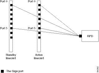
Figure 1. Multiple cores on the same line card
In the figure above, the RPD has multiple cores connected to the same active linecard. In order to support LCHA, RPD needs
to connect to the same port on the standby linecard. In this way, RPD has several standby cores to protect the active cores.
The standby core have the same resource as the active core.
When multiple cores connect to different active linecards, if they connect to different ports of the linecard, there will
have different standby cores. If active core connects to the same port on different linecard, they share one standby core.
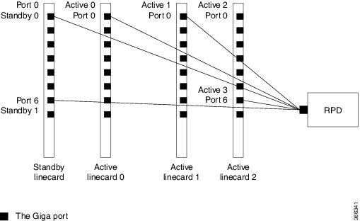
Figure 2. Multiple cores on different line cards
In the figure above, RPD have two standby cores. One standby core connects to port 6 of the standby linecard, it can protect
the active core which connects to port 6 of the active linecard 2. The other standby core connects to port 0 of the standby
linecard, it can protect the active cores connect to port 0 of linecard 0 and linecard 1. So for the standby core 0, it contains
the resource for both active core 0 and active core 1.
When active linecard 0 fails over to standby linecard, the standby core 1 will be deleted, the standby core 0 will bring the
resource of active core 0 to active. When linecard 2 fails over to standby linecard, the standby core 0 will be deleted, and
standby core 1 will become active for active core 3.
Compared to the SUP high availability recover process in iCMTS configuration, the Remote PHY SUP high availability recover
process has RPD status change as shown in the example below:
show cable rpd 0004.9f00.0625 lcha-cores
MAC Address     IP Address    I/F        State         Role  HA   Name
0004.9f00.0625  120.105.6.10  Te0/1/1    recovering    Pri   Act  node1
0004.9f00.0625  120.105.6.10  Te9/1/1    recovering    NA    Sby  node1

show cable rpd 0004.9f00.0625 lcha-cores
MAC Address     IP Address    I/F        State         Role  HA   Name
0004.9f00.0625  120.105.6.10  Te0/1/1    init(l2tp)    Pri   Act  node1
0004.9f00.0625  120.105.6.10  Te9/1/1    init(l2tp)    NA    Sby  node1

show cable rpd 0004.9f00.0625 lcha-cores
MAC Address     IP Address    I/F        State         Role  HA   Name
0004.9f00.0625  120.105.6.10  Te0/1/1    online        Pri   Act  node1
0004.9f00.0625  120.105.6.10  Te9/1/1    online        NA    Sby  node1
The status of the RPD changes from recovering to online, indicating that the SUP redundancy is working in the Remote PHY configuration.
The Cisco cBR Series Remote PHY Digital Physical Interface Card (DPIC) provides the Ethernet network connection between the
CCAP core and Remote PHY devices.
You can enable or disable RPHY link redundancy feature for a chassis. The redundancy state of a link is described using the
link mode and role.
The redundancy mode is the term that is used for the configured or administered designation of a link, and is determined during
the link configuration. The redundancy mode does not change during a switchover. There are two redundancy modes:
Primary mode: This is the default working link of a core interface. The primary link is fixed to port 0, 2, 4, 6 when the
link high availability is enabled.
Secondary mode: This mode provides protection to the primary link. The secondary link is fixed to port 1, 3, 5, 7 when the
link high availability is enabled.
The redundancy role is a dynamic entity that indicates the runtime or operational status of a port. The role changes only
during a link switchover. The entity has two states:
Active role: This link carries the RPHY data stream of the core interface. When the primary link is switched over to the secondary
link, the secondary link becomes the active link of the core interface.
Standby role: This link does not run any RPHY data traffic, but gets prepared to become active when the current active link
has failed. According to the physical state of the standby link, the standby link can be further distinguished into a standby-hot
link and standby-cold link. A standby-hot retains the link in the UP state. The 10-Gigabit Ethernet transceiver and TX power
are enabled in this case, and the 10-Gigabit Ethernet port state is UP in the directly connected switch or router. The link
of standby port is shut down, the TX power turned off and the 10-Gigabit Ethernet port state in the directly connected switch
or router is down.
cBR supports both standby-hot and standby-cold redundancy modes.
In 1+1 core link redundancy configuration, the secondary link is the backup link for the primary link. At any given time,
only one link (the active link) carries the RPHY control and data traffic for a core interface. The standby link provides
protection for only one primary link. Current 8x10G DPIC has eight 10G ports on front panel and 4x10G XFI ports to Cylons-R
40G. Each 10G XFI port provides two core interfaces sharing the total 10G bandwidth. For an 8-port DPIC card, you can provide
four 1+1 redundant groups.
When link high availability is enabled in the chassis, the secondary card supports link HA as do the other linecards. Each
linecard makes its link switchover decisions that is independently based on the physical link state.
How to Configure Remote PHY Line Card Redundancy
This section describes how to configure Remote PHY (R-PHY) Line Card Redundancy on Cisco cBR-8.
Configuring DPIC Ports
The Remote PHY LCHA, typically has separate paths for primary and secondary interfaces on the RPD. Hence, you should configure
separate VRFs for DPIC interfaces on the secondary LC.
The following example shows how to configure DPIC port to support Remote PHY Line Card Redundancy:
The following example shows how to configure Remote PHY Line Card Redundancy:
Router# configure terminal
Router(config)# redundancy
Router(config-red)# mode sso
Router(config-red)# linecard-group 0 internal-switch
Router(config-red-lc)# class 1:N
Router(config-red-lc)# member slot 8 primary
Router(config-red-lc)# member slot 6 secondary
Router(config-red-lc)# no revertive
Verifying Remote PHY Line Card Redundancy Configuration
To verify the Remote PHY line card redundancy configuration, use the example below:
Router# show redundancy linecard all
              LC     My         Peer        Peer      Peer
Slot Subslot  Group  State      State       Slot      Subslot  Role     Mode
---------------------------------------------------------------------------------
 8   -        0      Active     Stdby Warm  6         -        Active   Primary
 6   -        0      -          -           Multiple  None     Standby  Secondary

Router# show cable rpd lcha-cores
MAC Address     IP Address       I/F       State            Core Role  HA Role
0004.9f03.0055  80.6.16.15       Te6/1/0   online           Principal  Standby
0004.9f03.0055  80.6.16.15       Te8/1/0   online           Principal  Active
0004.9f03.0163  80.6.16.16       Te6/1/1   online           Principal  Standby
0004.9f03.0163  80.6.16.16       Te8/1/1   online           Principal  Active

Router# show cable rpd
MAC Address     IP Address       I/F       State            Core Role  HA Role
0004.9f03.0055  80.6.16.15       Te6/1/0   online           Principal  Active
0004.9f03.0163  80.6.16.16       Te6/1/1   online           Principal  Active
How to Configure DPIC Link Redundancy
This section describes how to configure DPIC Link Redundancy on Cisco cBR-8.
Configuring DPIC Link Redundancy
The link redundancy is disabled by default. You need to enable the link redundancy feature manually.
To set the DPIC link in the UP state, use the cable rphy link redundancy hot command.
To set the DPIC link in the standby-down state, use the cable rphy link redundancy cold command. For example:
Router# cable rphy link redundancy cold

RPHY Link HA: Cold mode enabled
Core Interface  Port  Mode        Role      Status
--------------  ----  ----------  --------  ------
Te 2/1/0        0     Primary     Active    Up
Te 2/1/0        1     Secondary   Standby   Ready
Te 2/1/2        2     Primary     Active    Up
Te 2/1/2        3     Secondary   Standby   Ready
Te 2/1/4        4     Primary     Active    Up
Te 2/1/4        5     Secondary   Standby   Ready
Te 2/1/6        6     Primary     Active    Up
Te 2/1/6        7     Secondary   Standby   Ready
To disable the link redundancy, run the no cable rphy link redundancy command.
Verifying DPIC Link Redundancy
To verify the DPIC link redundancy, go through the following steps:
To check the link redundancy of any of the DPIC slots, run the show redundancy digi-pic slot <0-9> command. See the following example:
Router# show redundancy digi-pic slot 0:


RPHY Link HA: Hot mode enabled
Core Interface Port Mode          Role       Status
-------------- ---- --------- ------- ---------------
Te 0/1/0        0    Primary       Active      Up
Te 0/1/0        1    Secondary     Standby     Up (“Ready” in standby-cold mode)
Te 0/1/2        2    Primary       Active      Up
Te 0/1/2        3    Secondary     Standby     Down
Te 0/1/4        4    Primary       Standby     Up (“Ready” in standby-cold mode)
Te 0/1/4        5    Secondary     Active      Up
Te 0/1/6        6    Primary       Active      Down
Te 0/1/6        7    Secondary     Standby     Down
To view the DPIC history, use the show redundancy digi-pic history slot <0-9> command. See the following example:
Router# show redundancy digi-pic history slot 2

Jun 25 2018 14:41:14 - 2/1/0: Auto switchover from port:1 link:down to port:0 link up, success.
Jun 25 2018 14:40:54 - 2/1/0: Auto switchover from port:0 link:down to port:1 link up, success.
Jun 25 2018 14:39:20 - 2/1/0: Enable LINKHA success.
Jun 25 2018 14:39:20 - 2/1/2: Enable LINKHA success.
Jun 25 2018 14:39:20 - 2/1/4: Enable LINKHA success.
Jun 25 2018 14:39:20 - 2/1/6: Enable LINKHA success.
Jun 25 2018 14:38:56 - 2/1/0: Disable LINKHA success.
Jun 25 2018 14:38:56 - 2/1/2: Disable LINKHA success.
Jun 25 2018 14:38:56 - 2/1/4: Disable LINKHA success.
Jun 25 2018 14:38:56 - 2/1/6: Disable LINKHA success.
Jun 25 2018 14:37:20 - 2/1/0: Manual switchover from port:1 to port:0, success.
Jun 25 2018 14:37:16 - 2/1/0: Manual switchover from port:0 to port:1, success.
Jun 25 2018 14:36:31 - 2/1/0: Enable LINKHA success.
Jun 25 2018 14:36:31 - 2/1/2: Enable LINKHA success.
Jun 25 2018 14:36:31 - 2/1/4: Enable LINKHA success.
Jun 25 2018 14:36:31 - 2/1/6: Enable LINKHA success.
To check the link redundancy of the TenGigabitEthernet 0/1/4, use the show redundancy digi-pic interface TenGigabitEthernet 0/1/4 command. See the following example:
Router# show redundancy digi-pic interface TenGigabitEthernet 0/1/4

Link HA  	: Hot mode enabled
HA State 	: In Failover
Reason   	: Manual Switchover

Port Mode      Role        Status
---- --------- ------- -----------
  4  Primary     Standby     Up (“Ready” in standby-cold mode)
  5  Secondary   Active      Up
You can view the DPIC history of the TenGigabitEthernet using the show redundancy digi-pic history interface TenGigabitEthernet <0-9>/1/<0, 2, 4, 6> command. See the following example:
Router# show redundancy digi-pic history interface TenGigabitEthernet 2/1/0

Jun 25 2018 14:41:14 - 2/1/0: Auto switchover from port:1 link:down to port:0 link up, success.
Jun 25 2018 14:40:54 - 2/1/0: Auto switchover from port:0 link:down to port:1 link up, success.
Jun 25 2018 14:39:20 - 2/1/0: Enable LINKHA success.
Jun 25 2018 14:38:56 - 2/1/0: Disable LINKHA success.
Jun 25 2018 14:37:20 - 2/1/0: Manual switchover from port:1 to port:0, success.
Jun 25 2018 14:37:16 - 2/1/0: Manual switchover from port:0 to port:1, success.
Jun 25 2018 14:36:31 - 2/1/0: Enable LINKHA success.
Jun 25 2018 14:36:02 - 2/1/0: Disable LINKHA success.
Jun 22 2018 00:01:24 - 2/1/0: Enable LINKHA success.
Jun 22 2018 00:00:12 - 2/1/0: Enable LINKHA success.
Jun 22 2018 00:00:08 - 2/1/0: Disable LINKHA success.
Jun 21 2018 23:59:21 - 2/1/0: Enable LINKHA success.
Jun 21 2018 23:52:21 - 2/1/0: Enable LINKHA success.
Jun 21 2018 23:50:21 - 2/1/0: Enable LINKHA success.
Jun 21 2018 23:50:17 - 2/1/0: Disable LINKHA success.
Jun 21 2018 23:43:30 - 2/1/0: Enable LINKHA success.
Jun 21 2018 23:42:02 - 2/1/0: Enable LINKHA success.
Jun 21 2018 23:41:53 - 2/1/0: Disable LINKHA success.
Jun 21 2018 20:43:05 - 2/1/0: Enable LINKHA success.
Feature Information for Remote PHY Redundancy
The following table provides release information about the feature or features described in this module. This table lists
only the software release that introduced support for a given feature in a given software release train. Unless noted otherwise,
subsequent releases of that software release train also support that feature.
Use Cisco Feature Navigator to find information about platform support and Cisco software image support. To access Cisco
Feature Navigator, go to www.cisco.com/go/cfn. An account on Cisco.com is not required.
Table 2. Feature Information for Remote PHY Redundancy
Feature Name
Releases
Feature Information
Remote PHY LCHA
Cisco 2x2 RPD Software 2.x
This feature was introduced in the Cisco 2x2 Remote PHY Device.
Remote PHY SUPHA
Cisco 2x2 RPD Software 2.x
This feature was introduced in the Cisco 2x2 Remote PHY Device.
DPIC Link Redundancy
Cisco 2x2 RPD Software 2.x
This feature was introduced in the Cisco 2x2 Remote PHY Device.

 Feedback