- Installation and Removal of the DC PEM
- Installation and Removal of the Fan Assembly
- Installation and Removal of the Supervisor Cards
- Installation and Removal of the RF Switch Card
- Installation and Removal of the TCC Cards
- Installation and Removal of the Line Cards
- Installation and Removal of the SFP Modules
Installing and Removing FRUs
This chapter tells you how to remove and replace Cisco RF Gateway 10 (RFGW-10) UEQAM field-replaceable units (FRUs). The Cisco RFGW-10 UEQAM supports hot-swapping, which allows installation, removal, and replacement of a component without powering off the system. When the system detects that a module has been installed or removed, it runs diagnostic and discovery routines automatically, acknowledges the presence or absence of the module, and resumes system operation without operator intervention.
The following sections describe how to install, remove and replace the various components:
- Installation and Removal of the DC PEM
- Installation and Removal of the Fan Assembly
- Installation and Removal of the Supervisor Cards
- Installation and Removal of the RF Switch Card
- Installation and Removal of the TCC Cards
- Installation and Removal of the Line Cards
- Installation and Removal of the SFP Modules

Warning Read the installation instructions before connecting the system to the power source. Statement 1004
Warning Only trained and qualified personnel should be allowed to install, replace, or service this equipment. Statement 1030
Warning This equipment must be grounded. Never defeat the ground conductor or operate the equipment in the absence of a suitably installed ground conductor. Contact the appropriate electrical inspection authority or an electrician if you are uncertain that suitable grounding is available. Statement 1024
Warning Before working on equipment that is connected to power lines, remove jewelry (including rings, necklaces, and watches). Metal objects will heat up when connected to power and ground and can cause serious burns or weld the metal object to the terminals. Statement 43
Warning Ultimate disposal of this product should be handled according to all national laws and regulations. Statement 1040
Installation and Removal of the DC PEM

Note To meet the electromagnetic interference (EMI) requirements, the DC power supply should be removed from the chassis if the PEM has failed or the circuit breaker is off.
This section describes how to remove and install the DC PEM (see Figure 5-1) for the Cisco RFGW-10 UEQAM.
Warning Hazardous voltage or energy is present on the backplane when the system is operating. Use caution when servicing. Statement 1034
Note The DC PEMs are hot-swappable, so in redundant mode there is no need to power down the chassis to replace or upgrade the DC PEMs.

Warning Blank faceplates and cover panels serve three important functions: they prevent exposure to hazardous voltages and currents inside the chassis; they contain electromagnetic interference (EMI) that might disrupt other equipment; and they direct the flow of cooling air through the chassis. Do not operate the system unless all cards, faceplates, front covers, and rear covers are in place. Statement 1029
Installing a DC PEM
This section describes how to install a DC PEM.
Warning Before performing any of the following procedures, ensure that power is removed from the DC circuit. Statement 1003
Warning A readily accessible two-poled disconnect device must be incorporated in the fixed wiring. Statement 1022
Warning This product requires short-circuit (overcurrent) protection, to be provided as part of the building installation. Install only in accordance with national and local wiring regulations. Statement 1045
Warning Use copper conductors only. Statement 1025
Warning When stranded wiring is required, use approved wiring terminations, such as closed-loop or spade-type with upturned lugs. These terminations should be the appropriate size for the wires and should clamp both the insulation and conductor. Statement 1002
To install a DC PEM, connect it to a power source, and verify its operation, do the following:
Before proceeding, read the following instructions:
- The color coding of the DC-input power supply leads depends on the color coding of the DC power source at your site. Typically, green or green/yellow is used for ground (GND), black for –48V on negative (–) terminal and red for RTN on the positive (+) terminal. Ensure that the lead color coding you choose for the DC-input power supply matches the lead color coding used at the DC power source.
- For DC-input power cables, select the appropriate wire gauge based on the National Electrical Code (NEC) and local codes for 60-amp service at nominal DC-input voltage (–48 VDC). Two pairs of cable leads - source DC (–) and source DC return (+), are required for each Power Distribution Unit (PDU). These cables are available from any commercial cable vendor. All input power cables for the chassis must have the same wire gauge and the cable lengths must match (with a 10 percent deviation). Each DC-input power cable is terminated at the PDU by a cable lug (included in the accessory kit). The cable lugs must be dual-hole, and have a 90 degree tongue (reference Panduit LCD4-14AF-L). They must fit over M6 terminal studs at 0.625-inch (15.88-mm) centers.
Note The DC-input power cables must be connected to the PDU terminal studs in the proper positive (+) and negative (–) polarity. In some cases, the DC cable leads are labeled, which is a safe indication of the polarity. However, you must verify the polarity by measuring the voltage between the DC cable leads. While measuring, the positive (+) lead and the negative (–) lead must always match the (+) and (–) labels on the PDU.
- An earth ground cable is required for each DC PDU. We recommend that you use at least 4-AWG multi-strand copper wire. This wire is not available from Cisco; it is available from any commercial cable vendor.
The ground wire cable lug (provided in the accessory kit) should be dual-hole, 90 degree tongue (reference Panduit LCD4-14AF-L), and fit over M6 terminal studs at 0.625 inch (15.88mm) centers.
Warning When you install the unit, the ground connection must always be made first and disconnected last. Statement 1046

Note To avoid hazardous conditions, all components in the area where DC input power is accessible must be properly insulated. Therefore, before installing the DC cable lugs, be sure to insulate the lugs according to the manufacturer's instructions.
Step 1 Ensure that the facility that feeds the DC -48V power supply to the chassis is turned off.
Step 2 Ensure that the breaker on the PEM power supply is turned off.
Step 3 Make sure that the chassis grounding is connected before you begin installing the DC power supply.
Step 4 Grasp the power supply handle with one hand. Place your other hand underneath it as you slowly insert the power supply into the bay. Do not fully install the DC power supply to the midplane connector, leave the power supply disconnected from the chassis by 1 inch.
Step 5 Locate the stud on the DC power supply for the GND connection, which must be connected first and follow these steps:
a. Using the provided grounding lug in the accessory kit, replace the washers and Kepnut screw in the following order:
b. Tighten the Kepnut screws on the power supply studs to the recommended torque of 18 in-lbs minimum to 22 in-lbs maximum.
Step 6 Attach the other end of the cable to the site ground connection.
Step 7 Before you connect the power supply to a power source, ensure that all site power and grounding requirements are met.
Step 8 Remove or rotate the plastic cover from the terminal block.
Note To avoid hazardous conditions, all components in the area where DC input power is accessible must be properly insulated. Therefore, before installing the DC cable lugs, be sure to insulate the lugs according to the manufacturer's instructions.
Step 9 Insert the negative lead cable first. Replace the ground lug with cable in the following order:
b. Ground lug with negative wire
Step 10 Tighten the Kepnut screw to the recommended torque of 18 in-lbs minimum to 22 in-lbs maximum.
Step 11 Repeat Step 7 and Step 8 for the RTN lead cable.
Note Secure the wires coming in from the terminal block so that they are not disturbed by casual contact.
Step 12 Replace and rotate the terminal block plastic cover back into position until it is locked.
Note Both DC inputs to the DC PEM must be connected and energized for the Cisco RFGW-10 UEQAM system to operate properly.
Step 13 Fully install the DC PEM into the power supply bay and tighten the captive fasteners on the faceplate to the chassis.
Step 14 Tighten the DC PEM captive fasteners to 12-16 in-lb torque.
Note Both DC inputs to the DC PEM must be connected and energized for the Cisco RFGW-10 UEQAM system to operate properly.
Step 15 Energize the facility DC power feeds to the power supply.
Step 16 Verify power supply operation by checking the power supply’s front panel LEDs. The –48 V1 and –48 V2 LEDs should illuminate green.
Step 17 Switch the circuit breaker switch to the On (|) position.
Step 18 Again verify the power supply operation by checking the power supply’s front panel LEDs. The –48 V1, –48 V2 and OUTPUT OK LEDs should illuminate green.
Step 19 Check the power supply and system status from the system console by entering the show power command. For more information on the commands, refer to the command reference publication for your chassis and software.
Removing a DC PEM
This section describes how to remove a DC PEM.
Warning Before performing any of the following procedures, ensure that power is removed from the DC circuit. Statement 1003
Step 1 Turn off the PEM in-line power switch.
Step 2 Ensure that the facility that feeds the DC -48V power supply to the chassis is turned off.
Step 3 Verify that power is off to the DC circuit on the power supply you are removing.
Note To meet the electromagnetic interference (EMI) requirements, the DC power supply should be removed from the chassis if the PEM has failed or the circuit breaker is off.
Step 4 Unscrew the top left-hand side captive fastener on the power supply faceplate (thumb screw) first, then unscrew the bottom right-hand side captive fastener.
Step 5 Grasp the power supply handle with one hand and pull until you feel the power supply disconnect from the midplane connector and move freely (approximately 1” removal from the chassis).
Step 6 Unhinge the terminal covers from the terminal blocks to expose the terminal block studs.
Step 7 Using a socket wrench and 10 mm socket disconnect the kepnut retaining the DC-input lugs from the terminal block.
Step 8 Repeat Step 6 and Step 7 for the second terminal block.
Step 9 Using a socket wrench and 10 mm socket disconnect the kepnut retaining the DC PEM ground lug from the power supply faceplate.
Warning When installing or replacing the unit, the ground connection must always be made first and disconnected last. Statement 1046
Step 10 Grasp the power supply handle with one hand. Place your other hand underneath as you slowly pull the power supply out of the bay.
Step 11 If the bay is to remain empty, install a blank power supply filler plate over the opening and secure it with the mounting screws. This protects the inner chassis from dust and prevents accidental contact with live voltage at the rear of the bay.
Warning Blank faceplates and cover panels serve three important functions: they prevent exposure to hazardous voltages and currents inside the chassis; they contain electromagnetic interference (EMI) that might disrupt other equipment; and they direct the flow of cooling air through the chassis. Do not operate the system unless all cards, faceplates, front covers, and rear covers are in place. Statement 1029
Installation and Removal of the Fan Assembly
This section describes how to install and remove the fan assembly of the Cisco RFGW-10 chassis.
Note Always use a wrist-strap or other grounding device to prevent ESD damage while handling the DS-48 line card.
Removing the Fan Assembly
Follow these steps to remove the existing chassis fan assembly:
Step 1 Loosen the three captive installation screws on the fan assembly front panel by turning them counterclockwise (see Figure 5-2).
Figure 5-2 Cisco RFGW-10 UEQAM System Fan Assembly

Warning When removing the fan tray, keep your hands and fingers away from the spinning fan blades. Let the fan blades completely stop before you remove the fan tray. Statement 258
Step 2 Grasp the fan assembly handles with both hands and pull it outward to disengage the midplane connector. Slide it out of the chassis and place it in a safe place. Do not touch the fans, hold the fan tray by the handles only.
Installing the Fan Assembly
Follow these steps to install the new fan assembly:
Step 1 Place the fan assembly into the fan assembly bay so it rests on the chassis, and then lift the fan assembly up slightly, aligning the top and sides with the bay opening.
Step 2 Gently slide the fan assembly into the chassis until the fan tray front panel makes contact with the chassis.
Note Apply a slow and even pressure on the fan assembly handles so that the fan tray does not tilt from side-to-side.
Step 3 Using a screwdriver, tighten the three front panel captive screws by turning them clockwise.
Note Tighten the fan tray captive screws to 6-8 in-lbs.
Verifying the Fan Assembly Installation
Note To check the operation of the fans, you need to power up the chassis.
Follow these steps to verify that the new fan assembly was installed correctly:
Step 1 Listen for the fans; you should immediately hear them operating. If you do not hear them, ensure that the fan assembly is inserted completely in the chassis and that the faceplate is flush with the chassis back panel.
Note The fan tray has multiple speeds based on the ambient air temperature conditions. The default control mode setting configures the fans at a maximum speed at startup. After startup, it may take up to 30 seconds for the fans to stabilize to the requested RPM.
Step 2 The fan tray LED should illuminate green.
Step 3 If after several attempts the fans do not operate, or if you experience trouble with the installation (for instance, if the captive installation screws do not align with the chassis holes), contact the Cisco TAC for assistance.
Installation and Removal of the Supervisor Cards
This section describes how to remove and install the Supervisor Cards.
Note When you handle the Supervisor Cards, use a wrist-strap or other grounding device to prevent ESD damage.
Installing the Supervisor Cards
The Cisco RFGW-10 UEQAM has vertical chassis slots that are numbered from left to right. The Supervisor Cards can be installed only in Slot 1 and/or 2.
To install a Supervisor Card in a Cisco RFGW-10 UEQAM chassis, do the following:
Step 1 Take necessary precautions to prevent ESD damage as described in the Preparing Your Site for Installation chapter.
Step 2 Ensure that you have enough clearance to accommodate any interface equipment that you will connect directly to the Supervisor Card ports.
Step 3 Loosen the captive installation screws that secure the Supervisor blank panel or the existing Supervisor Card (whichever is present).
Step 4 Remove the Supervisor blank panel or the existing Supervisor Card from Slot 1 or 2 as shown in Figure 5-3. If a Supervisor blank panel is installed, keep it for future use. To remove an existing Supervisor Card, follow the instructions in “Removing the Supervisor Card” section.
Figure 5-3 Supervisor Slot Locations In the Cisco RFGW-10 Chassis

Step 5 To install a Supervisor Card, turn the module sideways with the board facing right, grasp the switching module front panel with one hand and place your other hand under the board’s side edge to support the Supervisor Card as shown in Figure 5-4. Do not touch the printed circuit boards or the connector pins.
Figure 5-4 Installing the Supervisor Card in the Chassis

Step 6 Align the edges of the Supervisor Card’s printed circuit board with the slot guides on the top and bottom of the Cisco RFGW-10 UEQAM chassis, as shown in Figure 5-4.
Note The Supervisor Card slides into the chassis guides on the printed circuit board (PCB) edge and not on the sheet metal carrier edge.
Step 7 Pivot the two module ejector levers out and away from the faceplate.
Step 8 Carefully slide the Supervisor Card into the slot until the notches on both the ejector levers engage the chassis’ top and bottom.
Step 9 Using the thumb and the forefinger of each hand, simultaneously pivot in both the ejector levers to fully seat the Supervisor Card in the backplane connector.
Step 10 Use a screwdriver to tighten the captive installation screws on each end of the Supervisor Card’s faceplate.
Note Tighten the captive screws to 6-8 in-lbs.
Verifying the Status of the Supervisor Card
To check the status of the module, do the following:
Step 1 Ensure that the STATUS LED illuminates green (module operational).
Step 2 When the supervisor is online, enter the show module all command. Verify that the system acknowledges the new module and that the module's status is good.
Step 3 If the module is not operational, re-seat it. If the module is still not operational, contact your customer service representative.
Removing the Supervisor Card
Note If you are removing a Supervisor card from the chassis when the system is up and running, ensure that the card is in the standby mode. If the card is in active mode, execute the redundancy force-switchover command to change the card to the Standby mode, and then remove the card from the chassis.
To remove a Supervisor Card from a Cisco RFGW-10 UEQAM, do the following:
Step 1 Disconnect the network interface cables attached to the ports on the Supervisor Card that you intend to remove.
Step 2 Loosen the captive installation screws (see Figure 5-5).
Figure 5-5 Captive Installation Screws and Ejector Levers
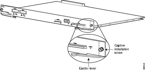
Step 3 Grasp the top and bottom ejector levers and simultaneously pivot the levers outward to release the Supervisor Card from the backplane connector. Figure 5-5 shows a close-up of the bottom ejector lever.
Step 4 Grasp the ejector levers of the Supervisor Card and pull it out of the slot until you can grab the carrier faceplate. Do not touch the printed circuit board components or the connector pins.
Step 5 Grasp the front panel of the Supervisor Card with one hand and place your other hand under the side PCB edge to support and guide it out of the slot. Do not touch the printed circuit board components or the connector pins.
Step 6 Carefully pull the Supervisor Card straight out of the slot, keeping your other hand under the PCB edge to guide it.
Step 7 Place the Supervisor Card on an antistatic mat or antistatic foam, or immediately install it in another slot.
Warning Blank faceplates and cover panels serve three important functions: they prevent exposure to hazardous voltages and currents inside the chassis; they contain electromagnetic interference (EMI) that might disrupt other equipment; and they direct the flow of cooling air through the chassis. Do not operate the system unless all cards, faceplates, front covers, and rear covers are in place. Statement 1029
Step 8 If the slot is to remain empty, install a Supervisor blank panel (part number RFGW-SUP-COVER= ).
Installation and Removal of the RF Switch Card
The RF switch cards are the RF coaxial termination for the Cisco RFGW-10 UEQAM chassis. There are 12 RF switch cards per Cisco RFGW-10 UEQAM chassis. (See Figure 5-6.) Each RF switch card connects to one port on each of the 10 DS-48 line cards. When removing and replacing the RF switch card, a physical port on each DS-48 line card is affected. All 12 RF switch cards are required for proper system operation.
The Cisco RFGW-10 UEQAM is a “cable once” system allowing removal of individual front-side DS-48 line cards without disconnecting any specific physical RF coaxial connection. All RF signaling is terminated on the rear-side RF switching modules. Each switch card supports a single UCH2 connector header and each UCH2 supports 10 MCX style coaxial connections per RF switch card.
Figure 5-6 12 RF Switch Cards Installed with UCH2

Note When you handle the RF switch cards, use a wrist-strap or other grounding device to prevent ESD damage.
Installing the RF Switch Card
The Cisco RFGW-10 UEQAM chassis has horizontal RF switch card slots that are numbered from top to bottom (Slots 1 through 12).
To install an RF switch card in a Cisco RFGW-10 UEQAM chassis, do the following:
Step 1 Take necessary precautions to prevent ESD damage as described in the Preparing Your Site for Installation chapter.
Step 2 Ensure that you have enough clearance to accommodate any interface equipment that you will connect directly to the RF switch card RF ports.
Step 3 Carefully move the cables away from the RF switch card slot to insert the RF switch card without obstruction.
Step 4 Hold the RF switch card by placing one hand under the board carrier to support the card and align the RF switch card carrier with the open chassis slot and slot card guides. See Figure 5-7.
Figure 5-7 RF Switch Card Installation

Step 5 Gently insert the RF switch card into the open slot while ensuring not to angle the card, which could create an interference with the cables or adjacent cards.
Step 6 Gently push the RF switch card front panel and the side captive screw pull tabs to fully insert and connect the midplane connectors.
Note While pushing the RF switch card into the card slot, balance the card to ensure that installs straight. Imbalance can create off center loading that can cause binding of the card and prevent full insertion of the RF switch card midplane connectors and require re-seating.
Step 7 Ensure the RF switch card is fully seated in the chassis. Use a screwdriver and gently tighten the two side captive screws. There may be a need to wiggle the card left or right if the captive screws are not aligned to the captive chassis nuts.
Note Tighten the RF switch card captive screws to 6-8 in-lbs.
Step 8 Bring the coaxial cables back across the RF switch card faceplate and align the UCH to the RF switch card coaxial connector guide pin holes. Align the red marking on the UCH facing left towards the red line on the left side of the RF switch card label. See Figure 5-8.
Note The UCH is keyed and can only be installed in one orientation to the RF switch card connector.
Figure 5-8 Aligning the UCH to the RF Switch Card Coaxial Connector

Step 9 While holding the UCH and the cables in place on the faceplate, use your fingers to tighten the lead screw. If the UCH and cables do not settle securely in place on the faceplate, wiggle the holder to re-settle the connectors.
Step 10 Use the flathead screwdriver to tighten the lead screw. Turn the lead screw clockwise until it no longer turns (10 in-lbs, maximum torque 15 in-lbs).
Note For a UCH2, as you turn the lead screw clockwise, the outer shroud on the UCH moves to cover the red line on the left side and the black line on the left side of the UCH. The half circles on the edge of the shroud close as the shroud fits over the UCH. Full engagement is indicated by visible metal-to-metal contact between the UCH and the faceplate (check the half circle cutouts).
Verifying the RF Switch Card Status
To verify the status of the RF switch card, do the following:
Step 1 Ensure that the POWER LED illuminates green (module operational).
Step 2 When the RF switch card is online, use the show module command to verify that the system acknowledges the new module and that the module's status is good.
Step 3 If the module is not operational, re-seat it. If the module is still not operational, contact your customer service representative.
Removing the RF Switch Card
To remove an RF switch card in a Cisco RFGW-10 UEQAM chassis, do the following:
Step 1 Take necessary precautions to prevent ESD damage as described in the Preparing Your Site for Installation chapter.
Step 2 Ensure that you have enough clearance to accommodate any interface equipment that you will connect directly to the RF switch card RF ports.
Step 3 Carefully move the cables away from the RF switch card slot to reach the lead screw on the UCH.
Step 4 Use the flathead screwdriver to loosen the lead screw on the UCH. Turn the lead screw counterclockwise. See Figure 6-4.
Step 5 Unscrew the lead screw until it is completely out of the faceplate on the RF switch card.
Step 6 Use the lead screw to pull the UCH and the cables straight out of the card (see Figure 5-9).
Figure 5-9 Using the Lead Screw to Pull the UCH

Step 7 Move the UCH and cables completely out of the RF switch card faceplate extraction direction.
Step 8 Loosen the captive installation screws on each side of the RF switch card faceplate.
Step 9 Flip out the extraction handle on the front faceplate of the RF switch card faceplate.
Step 10 Grasp the extraction handle with one hand and pull the RF switch card from the slot and place your other hand under the board carrier to support the card.
Step 11 Carefully pull the RF switch card straight out of the slot keeping your other hand under the sheet metal carrier to guide it.
Step 12 Place the RF switch card on an antistatic mat or antistatic foam.
Note If you are returning a card to the factory, after removing the card from the chassis immediately place it into an antistatic shielding bag.
Installation and Removal of the TCC Cards
This section describes how to install and remove the TCC cards in a Cisco RFGW-10 UEQAM chassis.
Note Whenever you handle the TCC card, use a wrist-strap or other grounding device to prevent ESD damage.
Installing the TCC Card
The Cisco RFGW-10 UEQAM has vertical TCC card chassis slots in the rear of the chassis that are numbered from right to left. The TCC cards can be installed only in slots 13 and 14.
To install a TCC card in a Cisco RFGW-10 UEQAM chassis, do the following:
Step 1 Take the necessary precautions to prevent ESD damage as described in the Preparing Your Site for Installation chapter.
Step 2 Ensure that you have enough clearance to accommodate any interface equipment that you will connect directly to the Supervisor Card ports.
Step 3 Loosen the captive installation screws that secure the TCC blank panel or the existing TCC card (whichever is present).
Note If a TCC card is currently installed in the chassis slot, disconnect the associated cabling before loosening the captive screws to maintain proper grounding of the TCC card.
Step 4 Remove the TCC blank panel or the existing TCC card from slot 13 or 14 as shown in Figure 5-10. If a TCC blank panel is installed, keep it for future use. To remove an existing TCC card, follow the instructions in “Removing the TCC Card” section.
Figure 5-10 TCC Card Slot Locations in the Cisco RFGW-10 Chassis

Step 5 To install a TCC card, turn the module sideways with the board facing right, grasp the TCC card front panel with one hand and place your other hand under the sheet metal carrier edge to support the TCC card. Do not touch the printed circuit boards or the connector pins.
Step 6 Align the edges of the TCC card sheet metal carrier edges with the slot guides on the top and bottom of the Cisco RFGW-10 UEQAM chassis.
Note The TCC card slides into the chassis guides on the sheet metal carrier edge.
Step 7 Pivot the two module ejector levers out and away from the faceplate (see Figure 5-11).
Figure 5-11 Pivoting the Two Ejector Levers

Step 8 Carefully slide the TCC card into the slot until the notches on both the ejector levers engage the chassis TCC slot’s top and bottom.
Step 9 Using the thumb and the forefinger of each hand, simultaneously pivot in both the ejector levers to fully seat the TCC card in the backplane connector.
Step 10 Use a screwdriver to tighten the captive installation screws on each end of the TCC card faceplate.
Note Tighten the captive screws to 6-8 in-lbs.
Verifying the Status of the TCC Card
To check the status of the module, do the following:
Step 1 Ensure that the POWER LED illuminates green (module operational).
Step 2 When the switch is online, use the show module command to verify that the system acknowledges the new module and that the module's status is good.
Step 3 If the module is not operational, re-seat it. If the module is still not operational, contact your customer service representative.
Removing the TCC Card
To remove a TCC card from a Cisco RFGW-10 UEQAM, do the following:
Step 1 Disconnect the network interface cables attached to the ports on the TCC card that you intend to remove.
Step 2 Loosen the captive installation screws (see Figure 5-12).
Figure 5-12 Captive Installation Screws and Ejector Levers

Step 3 Grasp the top and bottom ejector levers and simultaneously pivot the levers outward to release the TCC card from the backplane connector. Figure 5-12 shows a close-up of the bottom ejector lever.
Step 4 Grasp the ejector levers of the TCC card and pull it out of the slot until you can grab the carrier faceplate. Do not touch the printed circuit board components or the connector pins.
Step 5 Grasp the front panel of the TCC card with one hand and carefully pull the TCC card straight out of the slot.
Step 6 Place the TCC card on an antistatic mat or antistatic foam, or immediately install it in another slot.
Warning Blank faceplates and cover panels serve three important functions: they prevent exposure to hazardous voltages and currents inside the chassis; they contain electromagnetic interference (EMI) that might disrupt other equipment; and they direct the flow of cooling air through the chassis. Do not operate the system unless all cards, faceplates, front covers, and rear covers are in place. Statement 1029
Step 7 If the slot is to remain empty, install a TCC blank panel (part number RFGW-TCC-COVER=).
Installation and Removal of the Line Cards
Note For information on installing and removing the Cisco RFGW-10 DS-384 line card, see the Cisco RF Gateway 10 Downstream 384 Line Card Hardware Installation Guide.
This section describes how to remove and install the DS-48 line cards.
Note Always use a wrist-strap or other grounding device to prevent ESD damage while handling the DS-48 line card.
Installing the DS-48 Line Card
The Cisco RFGW-10 UEQAM has vertical chassis slots numbered from left to right. The DS-48 line cards can be installed only in Slot 3 through 13.
To install a DS-48 line card in a Cisco RFGW-10 UEQAM chassis, do the following:
Step 1 Take the necessary precautions to prevent ESD damage as described in Preparing Your Site for Installation chapter.
Step 2 Ensure that you have enough clearance to accommodate any interface equipment that you will connect directly to the Supervisor Card ports.
Step 3 Loosen the captive installation screws that secure the line card blank panel or the existing DS-48 line card (whichever is present).
Step 4 Remove the line card blank panel or the existing DS-48 line card from the appropriate RF capable slot as shown in Figure 5-13. If a blank panel is installed, keep it for future use. If you are removing an existing DS-48 line card, follow the instructions in “Removing the DS-48 Line Card” section.
Figure 5-13 DS-48 Line Cards (RF Slots 3 through 12) Locations in the Cisco RFGW-10 Chassis

Step 5 To install a DS-48 line card, turn the module sideways with the board facing right, grasp the DS-48 module front panel with one hand and place your other hand under the board’s side edge to support the line card as shown in Figure 5-14. Do not touch the printed circuit boards or the connector pins.
Figure 5-14 Installing the DS-48 Line Card in the Chassis

Step 6 Align the edges of the DS-48 line card carrier with the slot guides on the top and bottom of the Cisco RFGW-10 UEQAM chassis, as shown in Figure 5-14.
Note The DS-48 line cards slide into the chassis guides on the sheet metal carrier edge.
Step 7 Pivot the two module ejector levers out and away from the faceplate.
Step 8 Carefully slide the DS-48 line card into the appropriate slot until the notches on both the ejector levers engage the chassis top and bottom.
Step 9 Using your thumb and forefinger of each hand to simultaneously pivot in both the ejector levers to fully seat the DS-48 line card in the backplane connectors.
Note The DS-48 line card sheet metal carrier faceplate has holes on the top and bottom for aligning to the chassis pin features. This feature aids in positioning each line card faceplate within the chassis. See Figure 5-15.
Figure 5-15 RF Line Card Faceplate to Chassis Alignment Features

Step 10 Use a screwdriver to tighten the captive installation screws on each end of the DS-48 line card faceplate.
Note Tighten the captive screws to 6-8 in-lbs.
Verifying the Status of the DS-48 Line Card
To check the status of the module, do the following:
Step 1 Ensure that the STATUS LED illuminates green (module operational).
Step 2 When the DS-48 is online, use the show module command to verify that the system acknowledges the new module and that the module's status is good.
Step 3 If the module is not operational, re-seat it. If the module is still not operational, contact your customer service representative.
Removing the DS-48 Line Card
To remove a DS-48 line card from a Cisco RFGW-10 UEQAM, do the following:
Step 1 Disconnect the network interface cables attached to the ports on the DS-48 line card that you intend to remove.
Step 2 Loosen the captive installation screws.
Step 3 Grasp the top and bottom ejector levers and simultaneously pivot the levers outward to release the DS-48 line card from the backplane connector.
Step 4 Grasp the front panel of the DS-48 line card with one hand and place your other hand under the side sheet metal carrier edge to support and guide it out of the slot. Do not touch the printed circuit board components or the connector pins.
Step 5 Carefully pull the DS-48 line card straight out of the slot keeping your other hand under the sheet metal carrier edge to guide it.
Step 6 Place the DS-48 line card on an antistatic mat or antistatic foam, or immediately install it in another slot.
Note If you are returning a card to the factory, after removing the card from the chassis, immediately place it in an antistatic shielding bag.
Warning Blank faceplates and cover panels serve three important functions: they prevent exposure to hazardous voltages and currents inside the chassis; they contain electromagnetic interference (EMI) that might disrupt other equipment; and they direct the flow of cooling air through the chassis. Do not operate the system unless all cards, faceplates, front covers, and rear covers are in place. Statement 1029
Step 7 If the slot is to remain empty, install a line card blank panel (part number RFGW-LC-COVER= ).
Installation and Removal of the SFP Modules
The following sections describe how to install, remove, and maintain the SFP modules.
Installing SFP Modules
The Supervisor Engine and DS-48 line card can be configured with any combination of small form-factor pluggable (SFP) modules. The Cisco RF Gateway 10 supports the following SFP modules:
- SFP-GE-T 1000BASE-T SFP (NEBS 3 ESD) (328 feet or 100 m on Cat5 UTP)
- SFP-GE-S 1000BASE-SX short wavelength; with DOM (1804.4 feet or 550 m of MMF)
- SFP-GE-L 1000BASE-LX/LH short wavelength; with DOM (32808 feet or 10 Km on SMF)
- X2-10GB-SR 10GBASE-SR X2 Module (85.3 feet or 26 m on MMF)
- X2-10GB-LR 10GBASE-LR X2 Module (32808 feet or 10 km on SMF)
Warning Invisible laser radiation may be emitted from disconnected fibers or connectors. Do not stare into beams or view directly with optical instruments. Statement 1051
Figure 5-16 Connecting LC Connectors to the SFP Module
The SFP modules have three different types of latching devices used to secure and detach the SFP module from a switching module port. The three types of SFP modules are described in the following sections:
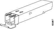
Mylar Tab SFP Modules
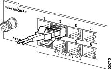
The Mylar tab SFP module (see Figure 5-17) has a tab that you must pull in order to remove the module from a switching module port.
Figure 5-17 Mylar Tab SFP Module
To insert the Mylar tab SFP module into a switching module port, line up the SFP module with the port, and slide it into place (see Figure 5-18).
Figure 5-18 Inserting a Mylar Tab SFP Module

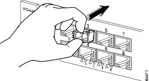
To remove the SFP module from the switching module port, pull the tab gently until the SFP module disengages from the port, and then pull the SFP module out (see Figure 5-19).
Figure 5-19 Removing a Mylar Tab SFP Module

Actuator/Button SFP Modules
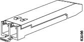
The actuator/button SFP module (see Figure 5-20) has a button that you must push to remove the SFP module from a switching module port.
Figure 5-20 Actuator/Button SFP Module
To insert the actuator/button SFP module into a switching module port, line up the SFP module with the port and slide it in until the actuator/button clicks into place (see Figure 5-21). Be sure not to press the actuator/button as you insert the SFP module because you might inadvertently disengage the SFP module from the port.
Figure 5-21 Inserting an Actuator/Button SFP Module

To remove an actuator/button SFP module from a switching module port, perform the following steps:
Step 1 Gently press the actuator/button on the front of the SFP module until it clicks and the latch mechanism activates, releasing the SFP module from the port (see Figure 5-22).
Step 2 Grasp the actuator/button between your thumb and index finger and carefully pull the SFP module from the port.
Figure 5-22 Press the Actuator/Button to Remove an SFP Module

Bale Clasp SFP Modules
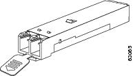
The bale clasp SFP module (see Figure 5-23) has a bale clasp that you use to secure the SFP module in a switching module port.
Figure 5-23 Bale Clasp SFP Module
To insert a bale clasp SFP module into a switching module port, perform the following steps:
Step 1 Close the bale clasp in the upward direction before inserting the SFP module.
Step 2 Line up the SFP module with the port and slide it into the port (see Figure 5-24).
Figure 5-24 Inserting a Bale Clasp SFP Module into a Switching Module Port
To remove a bale clasp SFP module from a switching module port, perform the following steps:
Step 1 Open the bale clasp on the SFP module: With your index finger, press the clasp downward as shown in Figure 5-25. If the bale clasp is obstructed and you cannot use your index finger to open it, use a small, flat-blade screwdriver or other long, narrow instrument to open the bale clasp as shown in Figure 5-26.
Step 2 Grasp the SFP module between your thumb and index finger and carefully remove it from the switching module port as shown in Figure 5-25.
Figure 5-25 Removing a Bale Clasp SFP Module

Figure 5-26 Opening a Bale Clasp with a Flat-Blade Screwdriver

 Feedback