Review the Cisco DNA Center Appliance Features

Appliance Hardware Specifications

Cisco supplies Cisco Digital Network Architecture (DNA) Center in the form of a rack-mountable, physical appliance. The first-generation Cisco DNA Center appliance (Cisco part number DN1-HW-APL) consists of a Cisco Unified Computing System (UCS) C220 M4 small form factor (SFF) chassis, with the addition of a Virtual Interface Card (VIC) 1227 in the mLOM slot. The Cisco DNA Center software image is preinstalled on the appliance, but must be configured for use.

The following table summarizes the appliance's hardware specifications.

Feature

Description

Chassis

One rack-unit (1RU) chassis

Processors

Two 22-core Intel Xeon E5-2699 v4 2.20 GHz processors

Memory

Eight 32-GB DDR4 2400 MHz registered DIMMs (RDIMMs)

Storage

  • Six 1.9-TB, 2.5-inch Enterprise Value 6G SATA solid state drives (SSDs)

  • Two 480-GB, 2.5-inch Enterprise Value 12G SATA SSDs

Disk Management (RAID)

  • RAID 1 on slots 1 through 4

  • RAID 10 on slots 5 through 8

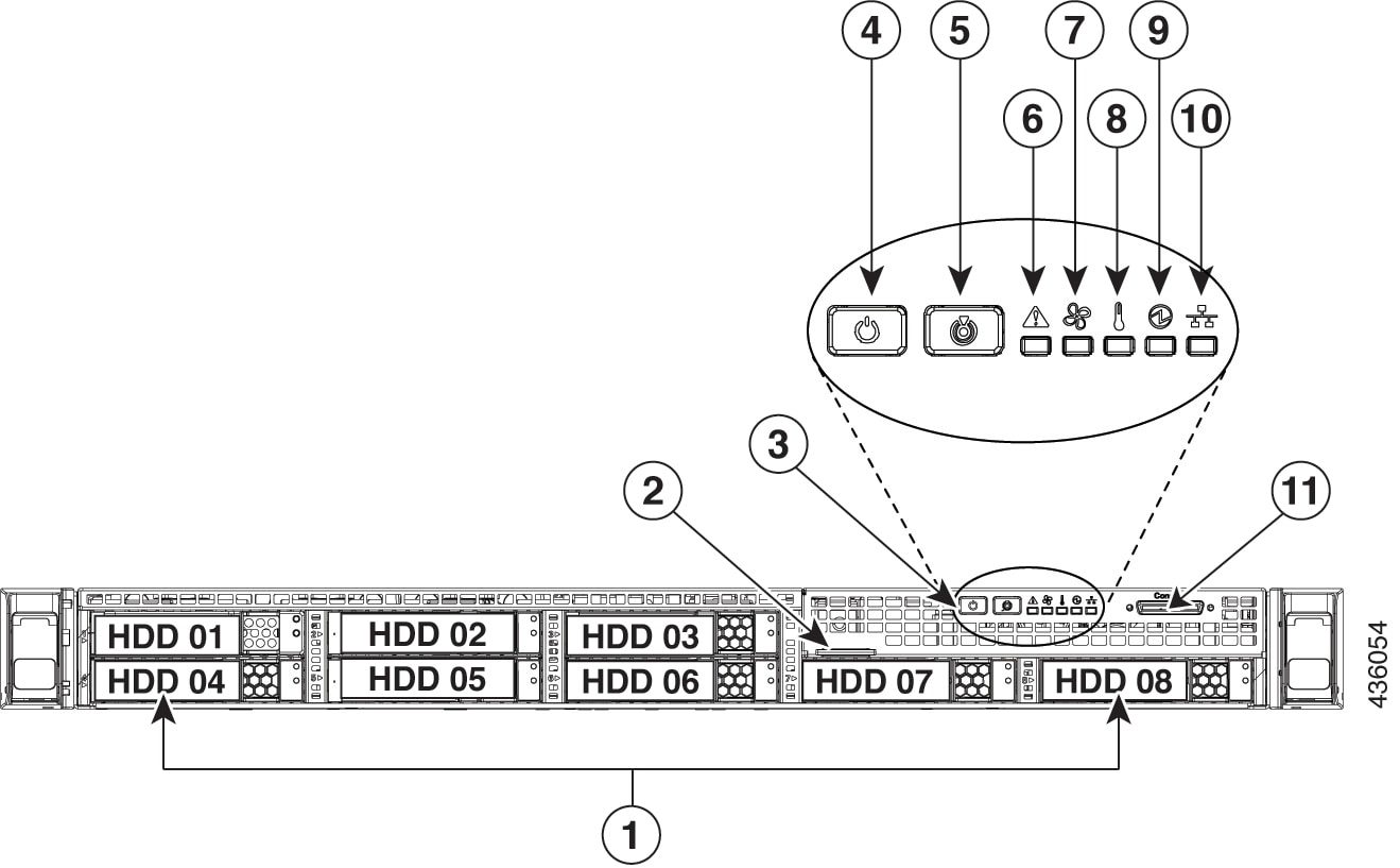
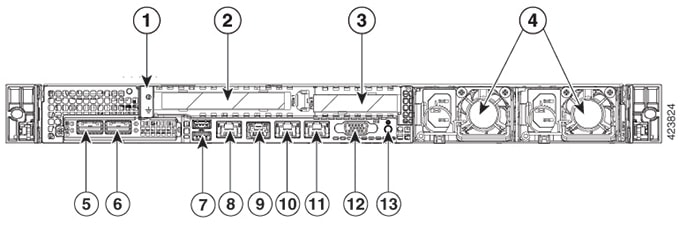
Network and Management I/O

Supported connectors:

  • Two 10-Gbps Ethernet ports on the Cisco UCS VIC 1227

  • One 1-Gbps Ethernet dedicated management port

  • Two 1-Gbps BASE-T Ethernet LAN ports

The following connectors are available but not typically used in the day-to-day operation of Cisco DNA Center:

  • One RS-232 serial port (RJ-45 connector)

  • One 15-pin VGA2 connector

  • Two USB 3.0 connectors

  • One front-panel KVM connector that is used with the KVM cable, which provides two USB 2.0, one VGA, and one serial (DB-9) connector

Power

  • Two 770-W AC power supplies

  • Redundant as 1+1

Cooling

Six hot-swappable fan modules for front-to-rear cooling

Video

Video Graphics Array (VGA) video resolution up to 1920 x 1200, 16 bpp at 60 Hz, and up to 256 MB of video memory

Front and Rear Panels

The following figures and tables describe the front and rear panels of the 44-core Cisco DNA Center appliance.

Figure 1. Appliance Front Panel

Component

Description

1

A total of eight drives are available on the appliance:

  • Six 1.9 TB SATA SSD

  • Two 480 GB SAS SSD

Each installed drive bay has a fault LED and an activity LED.

When the drive fault LED is:

  • Off: The drive is operating properly.

  • Amber: The drive has failed.

  • Amber, blinking: The drive is rebuilding.

When the drive activity LED is:

  • Off: There is no drive in the sled (no access, no fault).

  • Green: The drive is ready.

  • Green, blinking: The drive is reading or writing data.

2

Pull-out asset tag

3

Operations sub-panel buttons and LEDs. LED states for these buttons and the conditions they indicate are described in the following entries.

4

Power button/power status LED. When the LED is:

  • Off: There is no AC power to the appliance.

  • Amber: The appliance is in standby power mode. Power is supplied only to the Cisco Integrated Management Controller (CIMC) and some motherboard functions.

  • Green: The appliance is in main power mode. Power is supplied to all the server components.

5

Unit identification button and LED. When the LED is:

  • Blue: Unit identification is active.

  • Off: Unit identification is inactive.

6

System status LED. When the LED is:

  • Green: The appliance is running in a normal operating condition.

  • Green, blinking: The appliance is performing system initialization and memory checks.

  • Amber, steady: The appliance is in a degraded operational state, which may be due to one or more of the following causes:

    • Power supply redundancy is lost.

    • CPUs are mismatched.

    • At least one CPU is faulty.

    • At least one DIMM is faulty.

    • At least one drive in a RAID configuration failed.

  • Amber, blinking: The appliance is in a critical fault state, which may be due to one or more of the following:

    • Boot failed.

    • Fatal CPU and/or bus error was detected.

    • Server is in an over-temperature condition.

7

Fan status LED. When the LED is:

  • Green: All fan modules are operating properly.

  • Amber, steady: One fan module has failed.

  • Amber, blinking: Critical fault, two or more fan modules have failed.

8

Temperature status LED. When the LED is:

  • Green: The appliance is operating at normal temperature.

  • Amber, steady: One or more temperature sensors have exceeded a warning threshold.

  • Amber, blinking: One or more temperature sensors have exceeded a critical threshold.

9

Power supply status LED. When the LED is:

  • Green: All power supplies are operating normally.

  • Amber, steady: One or more power supplies are in a degraded operational state.

  • Amber, blinking: One or more power supplies are in a critical fault state.

10

Network link activity LED. When the LED is:

  • Green, blinking: One or more Ethernet LOM ports are link-active, with activity.

  • Green: One or more Ethernet LOM ports are link-active, but there is no activity.

  • Off: The Ethernet link is idle.

11

KVM connector. Used with a KVM cable that provides two USB 2.0, one VGA, and one serial connector.

Figure 2. Appliance Rear Panel

Component

Description

1

Grounding-lug hole (for DC power supplies)

2

PCIe riser 1/slot 1

3

PCIe riser 2/slot 2

4

Power supplies (up to two: redundant as 1+1). Each power supply has a power supply fault LED and an AC power LED.

When the fault LED is:

  • Off: The power supply is operating normally.

  • Amber, blinking: An event warning threshold has been reached, but the power supply continues to operate.

  • Amber, solid: A critical fault threshold has been reached, causing the power supply to shut down (for example, a fan failure or an over-temperature condition).

When the AC Power LED is:

  • Green, solid: AC power is OK, DC output is OK.

  • Green, blinking: AC power is OK, DC output is not enabled.

  • Off: There is no AC power to the power supply.

For more details, see Power Specifications.

5

10-Gbps Cluster Port (Port 2, enp10s0, Network Adapter 1): This is the second 10-Gbps port on the Cisco Virtual Interface Card (VIC) 1227 in the appliance mLOM slot. The rear panel labels it Port 2 and the Maglev Configuration wizard identifies it as enp10s0 and Network Adapter 1. Connect this port to a switch with connections to the other nodes in the Cisco DNA Center cluster.

This port has a link status (ACT) LED and a link speed (LINK) LED.

When the link status LED is:

  • Green, blinking: Traffic is present on the active link.

  • Green: Link is active, but there is no traffic present.

  • Off: No link is present.

When the link speed LED is:

  • Green: Link speed is 10 Gbps.

  • Amber: Link speed is 1 Gbps.

  • Off: Link speed is 100 Mbps or less.

Note

 
The enterprise and cluster ports must operate at 10 Gbps only.

6

10-Gbps Enterprise Port (Port 1, enp9s0, Network Adapter 4): This is the first 10-Gbps port on the Cisco Virtual Interface Card (VIC) 1227 in the appliance mLOM slot. The rear panel labels it Port 1 and the Maglev Configuration wizard identifies it as enp9s0 and Network Adapter 4. Connect this port to a switch with IP reachability to the networking equipment that Cisco DNA Center will manage.

This port has a link status (ACT) LED and a link speed (LINK) LED.

When the link status LED is:

  • Green, blinking: Traffic is present on the active link.

  • Green: Link is active, but there is no traffic present.

  • Off: No link is present.

When the speed LED is:

  • Green: Link speed is 10 Gbps.

  • Amber: Link speed is 1 Gbps.

  • Off: Link speed is 100 Mbps or less.

Note

 
The Cisco DNA Center appliance enterprise and cluster ports must operate at 10 Gbps only.

7

Two USB 3.0 ports

8

1-Gbps CIMC Port (M): This is the embedded port to the right of the two USB ports and to the left of the RJ45 serial port. The back panel labels it M and you assign an IP address to it when you enable browser access to the appliance's CIMC GUI (see Enable Browser Access to Cisco Integrated Management Controller). This port is reserved for out-of-band (OOB) management of the Cisco DNA Center appliance chassis and software. Connect this port to a switch that provides access to your dedicated OOB enterprise management network.

This port has a link status LED and a link speed LED. When the link status LED is:

  • Green, blinking: Traffic is present on the active link.

  • Green: Link is active, but there is no traffic present.

  • Off: No link is present.

When the speed LED is:

  • Green: Link speed is 1 Gbps.

  • Amber: Link speed is 100 Mbps.

  • Off: Link speed is 10 Mbps or less.

9

Serial port (RJ-45 connector)

10

1-Gbps Cisco DNA Center GUI Port (1, enp1s0f0, Network Adapter 2): This is the first Intel i350 1Gb Ethernet controller port. It is embedded on the appliance motherboard. The rear panel labels it 1 and the Maglev Configuration wizard identifies it as enp1s0f0 and Network Adapter 2. Connect this port to a switch that provides access to your dedicated enterprise management network.

This port has a link status LED and a link speed LED. When the status LED is:

  • Green, blinking: Traffic is present on the active link.

  • Green: Link is active, but there is no traffic present.

  • Off: No link is present.

When the speed LED is:

  • Green: Link speed is 1 Gbps.

  • Amber: Link speed is 100 Mbps.

  • Off: Link speed is 10 Mbps or less.

11

1-Gbps Cloud Port (2, enp1s0f1, Network Adapter 3): This is the second embedded 1Gbps Ethernet controller port. The rear panel labels it 2 and the Maglev Configuration wizard identifies it as enp1s0f1 and Network Adapter 3. This port is optional. It is used for connecting to the Internet when it is not possible to do so via the 10-Gbps enterprise port (Port 1, enp9s0, Network Adapter 4).

This port has a link status LED and a link speed LED. When the link status LED is:

  • Green, blinking: Traffic is present on the active link.

  • Green: Link is active, but there is no traffic.

  • Off: No link is present.

When the speed LED is:

  • Green: Link speed is 1 Gbps.

  • Amber: Link speed is 100 Mbps.

  • Off: Link speed is 10 Mbps or less.

12

VGA video port (DB-15). This panel area around this port is blue.

13

Blue LED locator button

Physical Specifications

The following table lists the physical specifications for the appliance.

Table 1. Physical Specifications

Description

Specification

Height

1.7 in. (4.32 cm)

Width

16.89 in. (43.0 cm)

Including handles:

18.98 in. (48.2 cm)

Depth (length)

29.8 in. (75.6 cm)

Including handles:

30.98 in. (78.7 cm)

Front Clearance

3 in. (76 mm)

Side Clearance

1 in. (25 mm)

Rear Clearance

6 in. (152 mm)

Maximum weight (fully loaded chassis)

37.9 lb. (17.2 kg)

Environmental Specifications

The following table lists the environmental specifications for the Cisco DNA Center appliance.

Table 2. Environmental Specifications

Description

Specification

Temperature, operating

41 to 95°F (5 to 35°C)

Derate the maximum temperature by 1°C for every 1000 ft. (305 meters) of altitude above sea level.

Temperature, nonoperating (when the appliance is stored or transported)

–40 to 149°F (–40 to 65°C)

Humidity (RH), operating

10 to 90%, noncondensing at 82°F (28°C)

Humidity, nonoperating

5 to 93% at 82°F (28°C)

Altitude, operating

0 to 10,000 ft. (0 to 3,000 m)

Altitude, nonoperating (when the appliance is stored or transported)

0 to 40,000 ft. (0 to 12,192 m)

Sound power level, measure A-weighted per ISO7779 LwAd (Bels), operation at 73°F (23°C)

5.4

Sound pressure level, measure A-weighted per ISO7779 LpAm (dBA), Operation at 73°F (23°C)

37

Power Specifications

The specifications for the two 770 W AC power supplies (Cisco part number UCSC-PSU1-770W) provided with the Cisco DNA Center appliance are listed in the table below.

Table 3. AC Power Supply Specifications

Description

Specification

AC input voltage

Nominal range: 100–120 VAC, 200–240 VAC

Range: 90–132 VAC, 180–264 VAC

AC input frequency

Nominal range: 50 to 60 Hz

(Range: 47–63 Hz)

Maximum AC input current

9.5 A at 100 VAC

4.5 A at 208 VAC

Maximum input volt-amperes

950 VA at 100 VAC

Maximum output power per PSU

770 W at 100–120 VAC

Maximum inrush current

15 A at 35° C

Maximum hold-up time

12 ms at 770 W

Power supply output voltage

12 VDC

Power supply standby voltage

12 VDC

Efficiency rating

Climate Savers Platinum Efficiency (80Plus Platinum certified)

Form factor

RSP2

Input connector

IEC320 C14


Note


You can get more specific power information for the exact configuration of your appliance by using the Cisco UCS Power Calculator: http://ucspowercalc.cisco.com


10 Gigabit Ethernet Switches

The following table lists the 10 Gigabit Ethernet Cisco switches that can currently be brought up from the first-generation Cisco DNA Center appliance. This table will be updated as more switches are tested.

Cisco Switch Cisco Part Number Comment

Cisco Nexus 5672UP

N5K-C5672UP

Cisco Catalyst 6880-X

C6880-X-LE

Cisco Nexus 7700 (6-Slot)

N77-C7706

Tested with the Cisco Nexus 7700 Switch Supervisor2 Enhanced Module (Cisco part number N77-SUP2E) installed.

In order for the remaining switches in this table to function properly, ensure that the following settings are configured for both your switch and your Cisco DNA Center appliance:

  • Default VLAN: Specify the same port number on your appliance and switch.

  • VLAN Mode: Set Trunk mode.

See Steps 3 and 4 in Execute Preconfiguration Checks.

Cisco Catalyst 3850-48XS-S

WS-C3850-48XS-S

Cisco Catalyst 4500X-32 SFP+

WS-C4500X-32SFP+

Cisco Catalyst C9500-40X-E

C9500-40X

Cisco Catalyst 3650-48PQ-E

WS-C3650-48PQ-E