|
Step 2
|
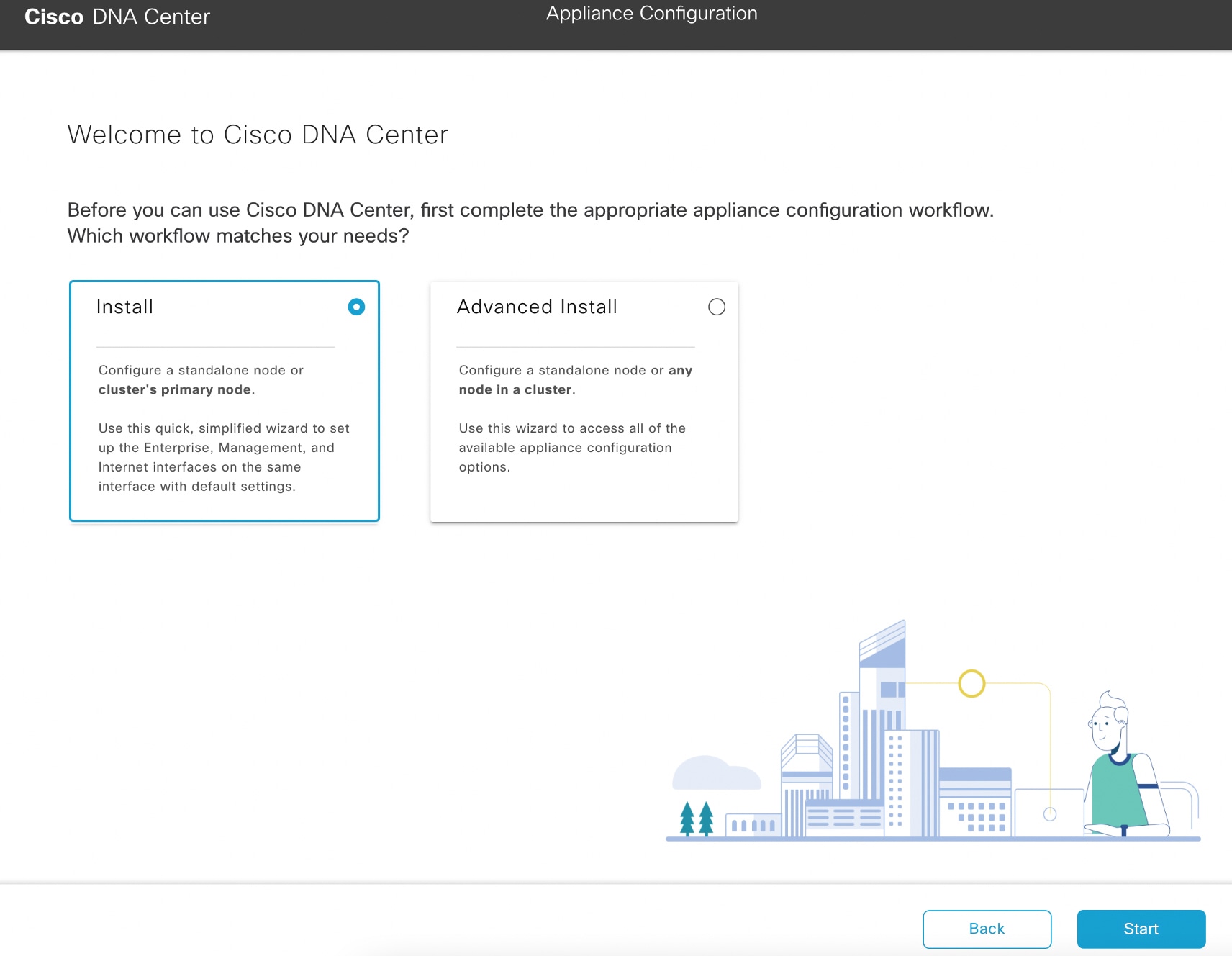
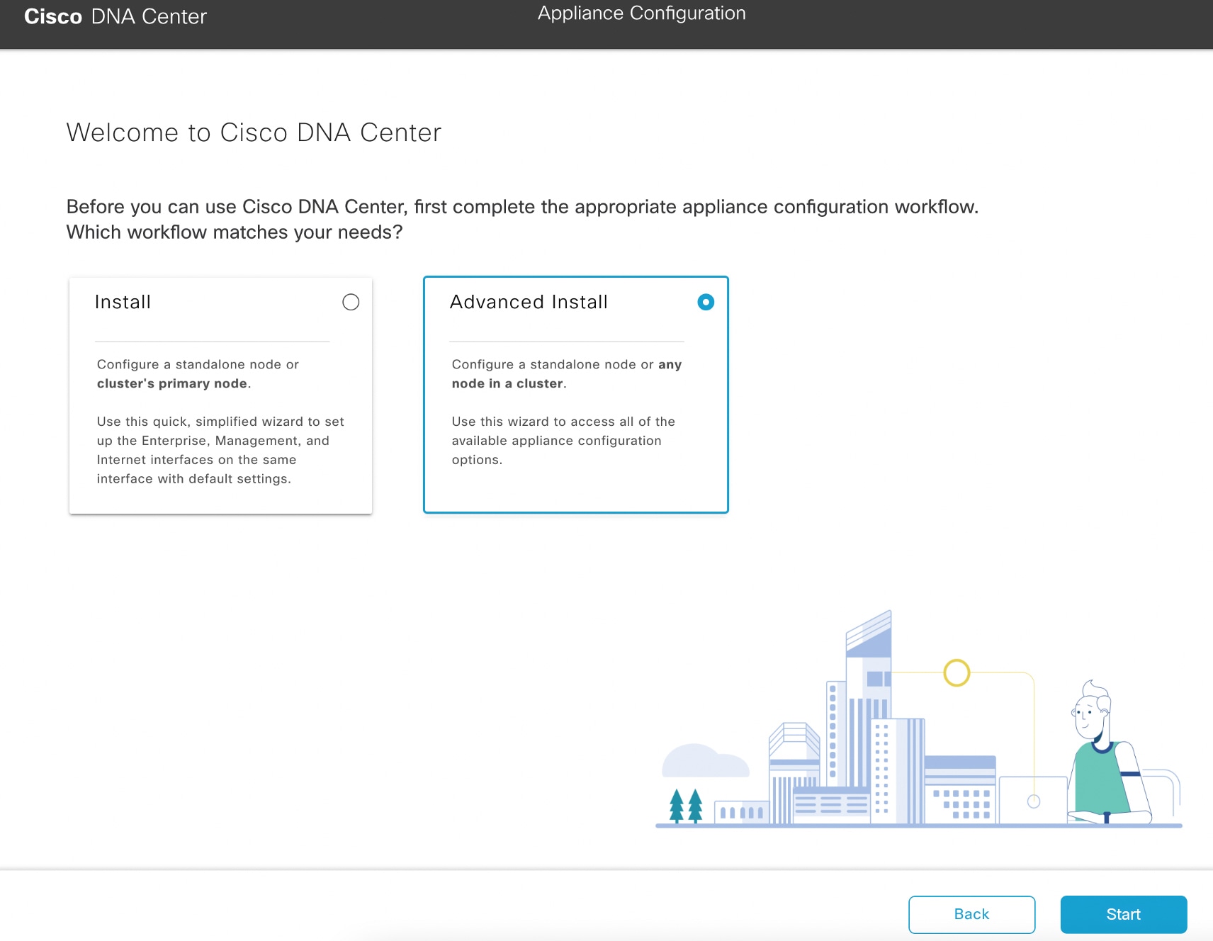
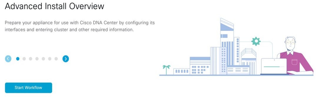
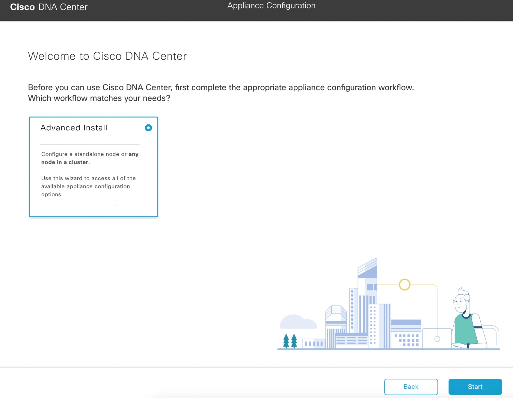
Complete the Advanced Install wizard:
-
Click Next.
The Will this appliance join a cluster? screen opens.

-
Click the No radio button (as you are configuring your cluster's primary node), then click Next.
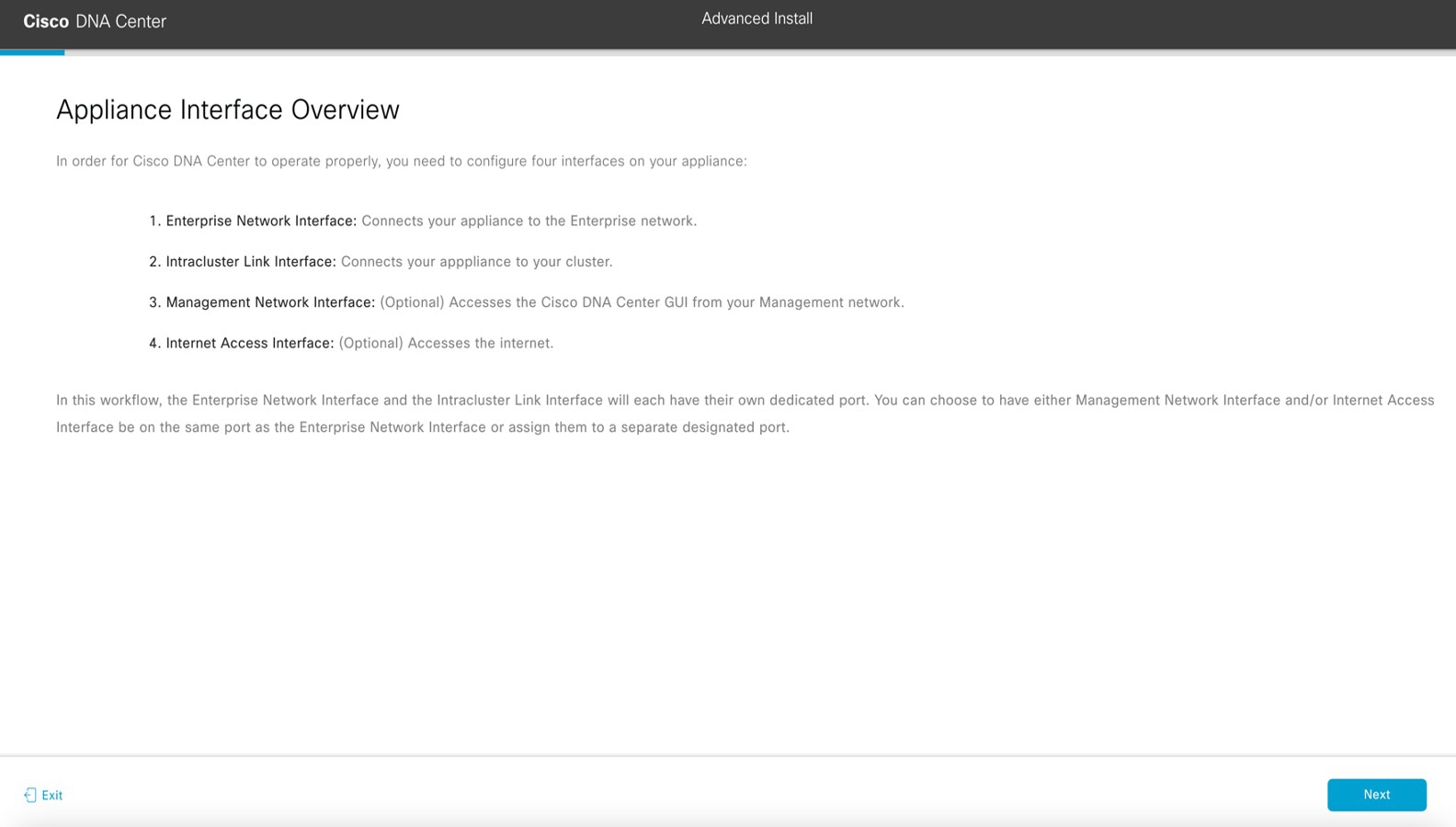
The How would you like to set up your appliance interfaces? screen opens.
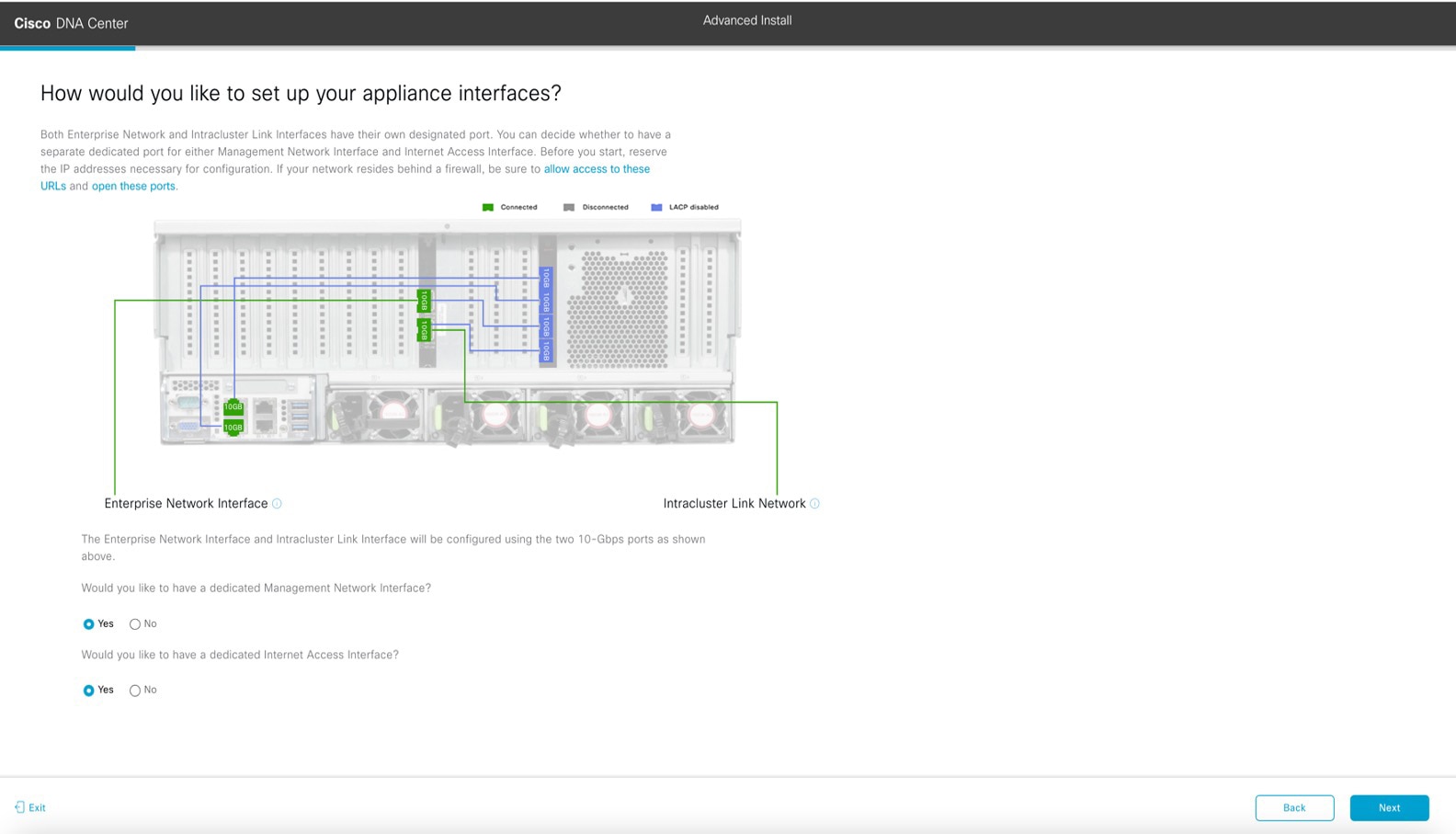 If your network resides behind a firewall, do the following:
-
Click the allow access to these URLs link to view a popup window that lists the URLs that Cisco DNA Center must be able to access.
-
Click the open these ports link to view a popup window that lists the network service ports that must be available for Cisco DNA Center to use.
-
Indicate whether you want to configure dedicated Management and Internet Access interfaces, then click Next.
The Configure Your Enterprise Network Interface screen opens.

-
Enter configuration values for the Enterprise interface.
As explained in Interface Cable Connections, this is a required interface used to link the appliance to the enterprise network. See Required IP Addresses and Subnets and Required Configuration Information for a more detailed description of the values you need to enter.
Table 3. Primary Node Entries for the Enterprise Interface
|
LACP Mode slider
|
Choose one of the following network interface controller (NIC) bonding modes for the Enterprise interface:
-
Active-Backup mode: This mode provides fault tolerance by aggregating two Ethernet interfaces into a single logical channel. When the interface
that's currently active goes down, the other interface takes its place and becomes active.
-
LACP mode: This mode aggregates two Ethernet interfaces that share the same speed and duplex settings into a single logical channel.
This provides load balancing and higher bandwidth.
For more information about Cisco DNA Center's implementation of NIC bonding, see NIC Bonding Overview.
|
|
Host IP Address field
|
Enter the IP address for the Enterprise port. This is required.
|
|
Subnet Mask field
|
Enter the netmask for the port's IP address. This is required.
|
|
Default Gateway IP Address field
|
Enter a default gateway IP address to use for the port.
|
Important
|
Ensure that you enter a default gateway IP address for at least one of your appliance's interfaces. Otherwise, you will not
be able to complete the configuration wizard.
|
|
Note
|
You designated this interface to use the default gateway assigned to it by a DHCP server. Complete the following steps to
specify a different gateway:
-
Delete the IP address that is currently listed in this field and then click Exit.
This will bring you back to the first wizard screen.
-
Return to the Enterprise port's wizard screen and enter the gateway IP address you want to use.
|
|
|
DNS field
|
Enter the IP address of the preferred DNS server. To enter additional DNS servers, click the Add (+) icon.
|
Important
|
For each appliance in your cluster, configure a maximum of three DNS servers. Problems can occur if you configure more than
three DNS servers for a node.
|
|
|
Add/Edit Static Route link
|
To configure a static route, click this link and then do the following:
-
Enter the route's network IP prefix, subnet mask, and nexthop IP address.
To configure additional static routes, click +.
-
Click Add.
|
From here, do one of the following:
-
To close the wizard, click Exit. A popup window appears, indicating that the settings you have entered up to this point will be saved. Click Exit again to confirm that you want to close the wizard. When you restart the wizard and return to this screen, the settings that
you entered previously will already be populated.
-
To return to the previous wizard screen, click Back.
-
To proceed to the next wizard screen, click Next.
The wizard validates the information you have entered, confirms that the port is up, and notifies you of any settings that
need to be changed before you can proceed with the wizard. If the settings you have entered are valid and the port is up,
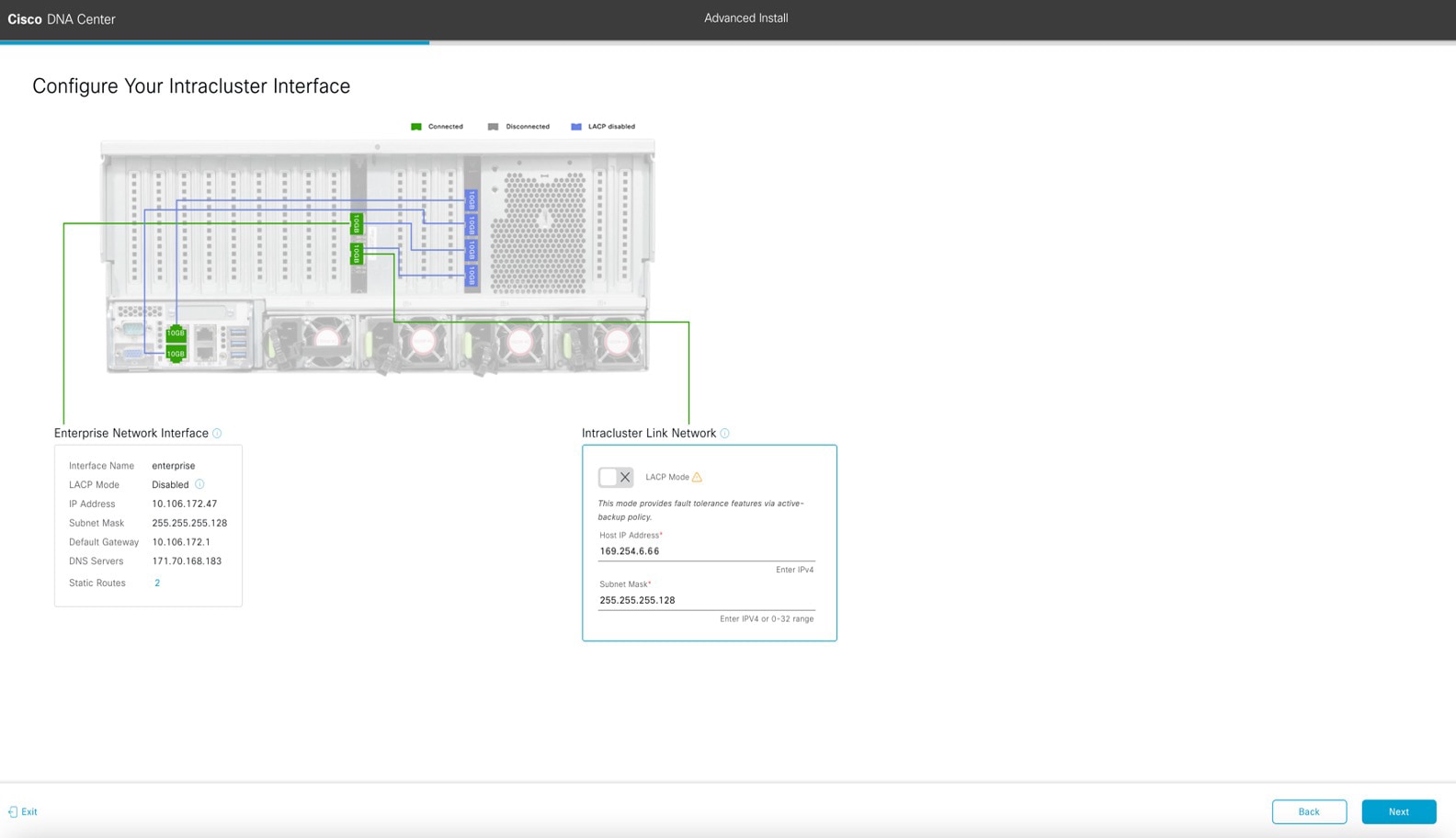
the wizard's Configure Your Intracluster Interface screen opens.
-
Enter configuration values for your Intracluster interface.
As explained in Interface Cable Connections, this required port is used to link the appliance to your cluster. See Required IP Addresses and Subnets and Required Configuration Information for a more detailed description of the values you need to enter.
|
Note
|
-
If you opted to configure the Enterprise and Internet Access interfaces on the same port, complete this step and then proceed
to Step 2f (which describes how to configure your Management interface).
-
If you opted to configure the Enterprise and Management interfaces on the same port, complete this step and then skip ahead
to Step 2g (which describes how to configure your Internet Access interface).
-
If you opted to configure the Enterprise, Management, and Internet Access interfaces on the same port, complete this step
and then skip ahead to Step 2h.
|
Table 4. Primary Node Entries for the Intracluster Interface
|
LACP Mode slider
|
Choose one of the following NIC bonding modes for the Intracluster interface:
-
Active-Backup mode: This mode provides fault tolerance by aggregating two Ethernet interfaces into a single logical channel. When the interface
that's currently active goes down, the other interface takes its place and becomes active.
-
LACP mode: This mode aggregates two Ethernet interfaces that share the same speed and duplex settings into a single logical channel.
This provides load balancing and higher bandwidth.
For more information about Cisco DNA Center's implementation of NIC bonding, see NIC Bonding Overview.
|
|
Host IP Address field
|
Enter the IP address for the Cluster port. This is required. Note that you cannot change the address of the Cluster port later.
|
|
Subnet Mask field
|
Enter the netmask for the port's IP address. This is required.
|
From here, do one of the following:
-
To close the wizard, click Exit. A popup window appears, indicating that the settings you have entered up to this point will be saved. Click Exit again to confirm that you want to close the wizard. When you restart the wizard and return to this screen, the settings that
you entered previously will already be populated.
-
To return to the previous wizard screen, click Back.
-
To proceed to the next wizard screen, click Next.
The wizard validates the information you have entered, confirms that the port is up, and notifies you of any settings that
need to be changed before you can proceed with the wizard. If the settings you have entered are valid and the port is up,
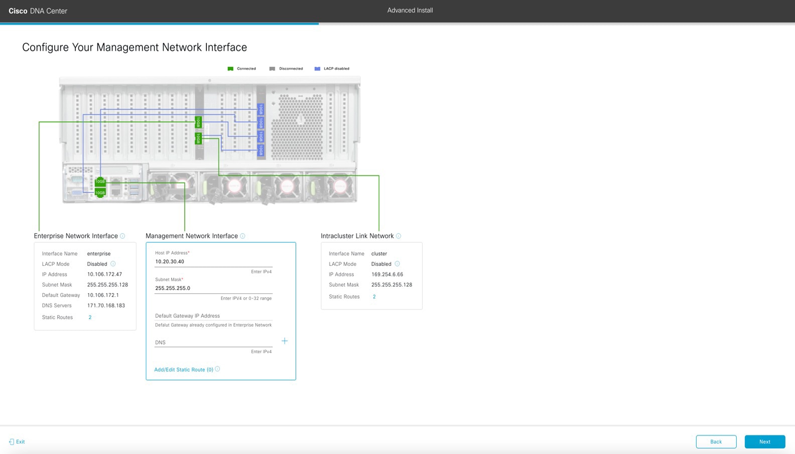
the wizard's Configure Your Management Network Interface screen opens.
-
(Optional) Enter configuration values for the Management port.
As explained in Interface Cable Connections, this port is used to access the Cisco DNA Center GUI from your management network. If you chose to configure a dedicated Management interface, enter the information described
in the following table. (See Required IP Addresses and Subnets and Required Configuration Information for a more detailed description of the values you need to enter.)
|
Note
|
If you opted to configure the Enterprise and Internet Access interfaces on the same port, complete this step and then skip
ahead to Step 2h.
|
Table 5. Primary Node Entries for the Management Port
|
Host IP Address field
|
Enter the IP address for the Management port.
|
|
Subnet Mask field
|
Enter the netmask for the port's IP address.
|
|
Default Gateway IP Address field
|
Enter a default gateway IP address to use for the port.
|
Important
|
Ensure that you enter a default gateway IP address for at least one of your appliance's interfaces. Otherwise, you will not
be able to complete the configuration wizard.
|
|
|
DNS field
|
Enter the IP address of the preferred DNS server. To enter additional DNS servers, click the Add (+) icon.
|
Important
|
-
For NTP, ensure port 123 (UDP) is open between Cisco DNA Center and your NTP server.
-
For each appliance in your cluster, configure a maximum of three DNS servers. Problems can occur if you configure more than
three DNS servers for a node.
|
|
|
Add/Edit Static Route link
|
To configure a static route, click this link and then do the following:
-
Enter the route's network IP prefix, subnet mask, and nexthop IP address.
To configure additional static routes, click +.
-
Click Add.
|
From here, do one of the following:
-
To close the wizard, click Exit. A popup window appears, indicating that the settings you have entered up to this point will be saved. Click Exit again to confirm that you want to close the wizard. When you restart the wizard and return to this screen, the settings that
you entered previously will already be populated.
-
To return to the previous wizard screen, click Back.
-
To proceed to the next wizard screen, click Next.
The wizard validates the information you have entered, confirms that the port is up, and notifies you of any settings that
need to be changed before you can proceed with the wizard. If the settings you have entered are valid and the port is up,
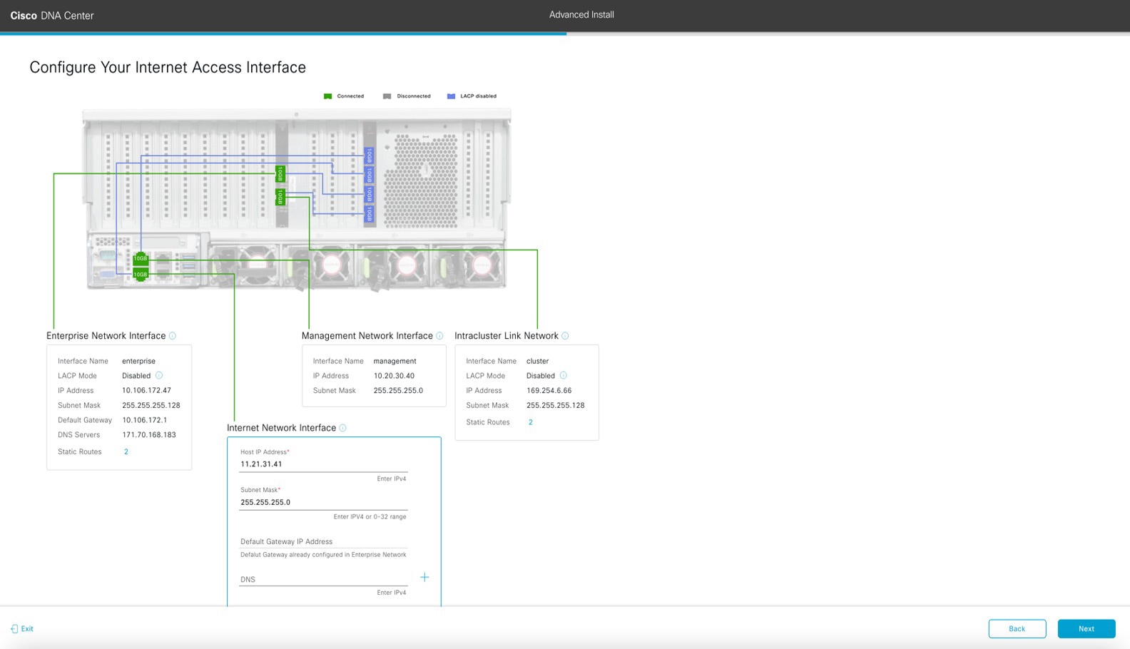
the wizard's Configure Your Internet Access Interface screen opens.
-
(Optional) Enter configuration values for the Internet Access interface.
As explained in Interface Cable Connections, this is an optional port used to link the appliance to the Internet when you cannot do so through the Enterprise port. If
you chose to configure a dedicated Internet Access interface, enter the information described in the following table. (See
Required IP Addresses and Subnets and Required Configuration Information for a more detailed description of the values you need to enter.)
Table 6. Primary Node Entries for the Internet Access Port
|
Host IP Address field
|
Enter the IP address for the Internet Access port.
|
|
Subnet Mask field
|
Enter the netmask for the port's IP address. This is required if you entered an IP address in the previous field.
|
|
Default Gateway IP Address field
|
Enter a default gateway IP address to use for the port.
|
Important
|
Ensure that you enter a default gateway IP address for at least one of your appliance's interfaces. Otherwise, you will not
be able to complete the configuration wizard.
|
|
|
DNS field
|
Enter the IP address of the preferred DNS server. To enter additional DNS servers, click the Add (+) icon.
|
Important
|
For each appliance in your cluster, configure a maximum of three DNS servers. Problems can occur if you configure more than
three DNS servers for a node.
|
|
|
Add/Edit Static Route link
|
To configure a static route, click this link and then do the following:
-
Enter the route's network IP prefix, subnet mask, and nexthop IP address.
To configure additional static routes, click +.
-
Click Add.
|
From here, do one of the following:
-
To close the wizard, click Exit. A popup window appears, indicating that the settings you have entered up to this point will be saved. Click Exit again to confirm that you want to close the wizard. When you restart the wizard and return to this screen, the settings that
you entered previously will already be populated.
-
To return to the previous wizard screen, click Back.
-
To proceed to the next wizard screen, click Next.
The wizard validates the information you have entered, confirms that the port is up, and notifies you of any settings that
need to be changed before you can proceed with the wizard. If the settings you have entered are valid and the port is up,
the wizard's Interface to Port Configuration screen opens.
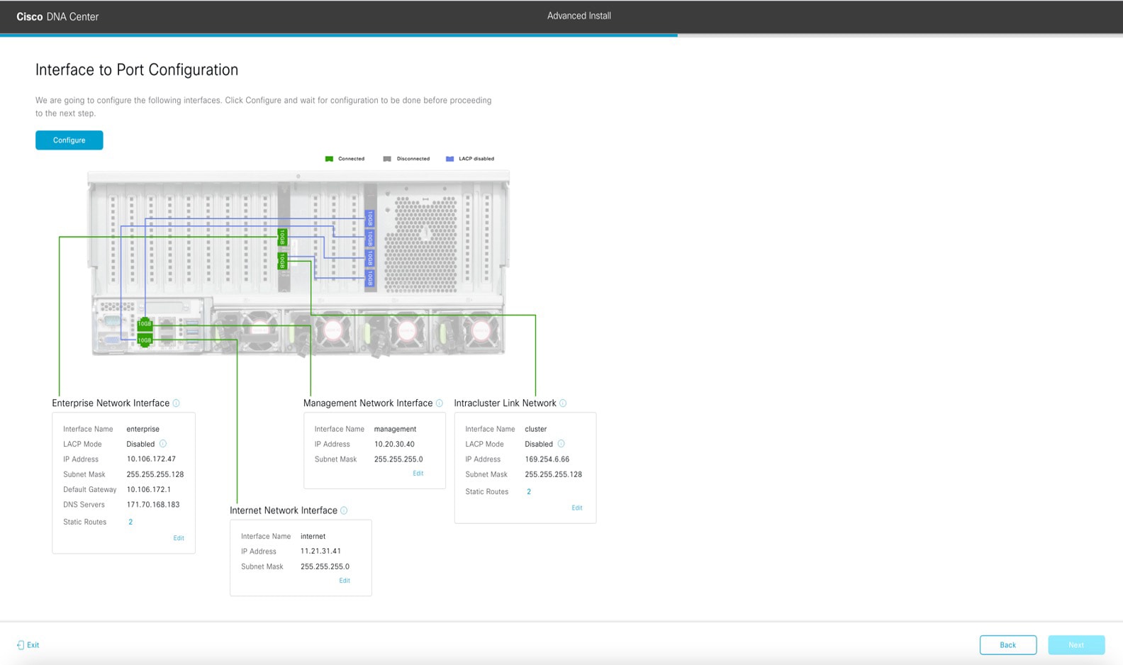
-
Review the settings that you have entered for the primary node's interfaces.
If you need to make any changes, click the Edit link for the relevant interface.
-
When you are happy with the interface settings, click Configure.
-
After initial interface configuration has completed, click Next to proceed to the next wizard screen.
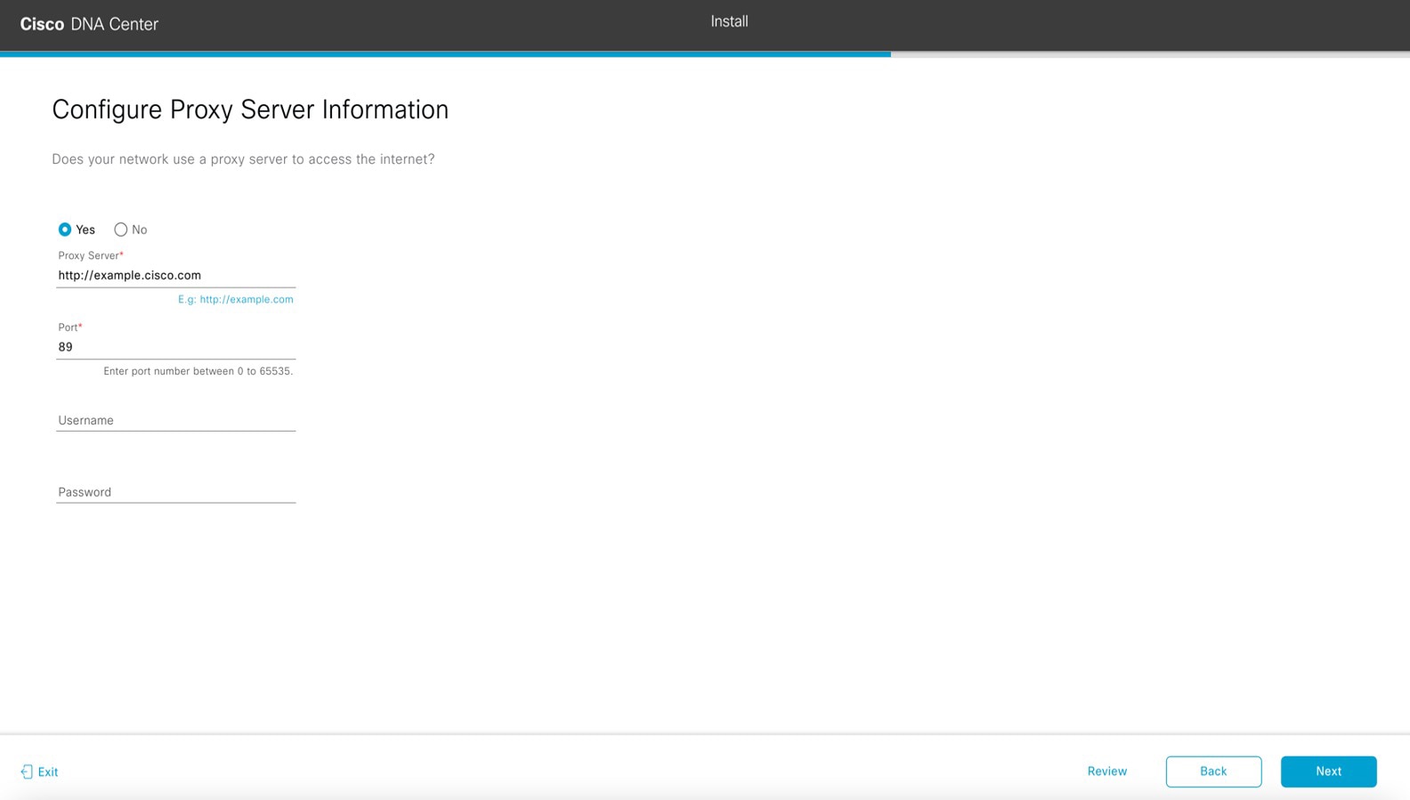
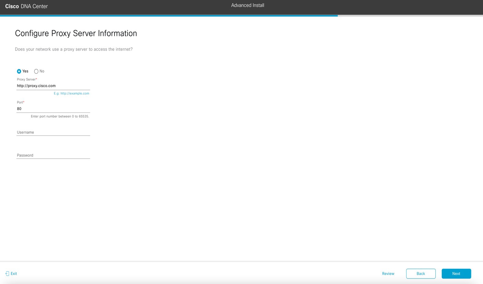
The wizard's Configure Proxy Server Information screen opens.
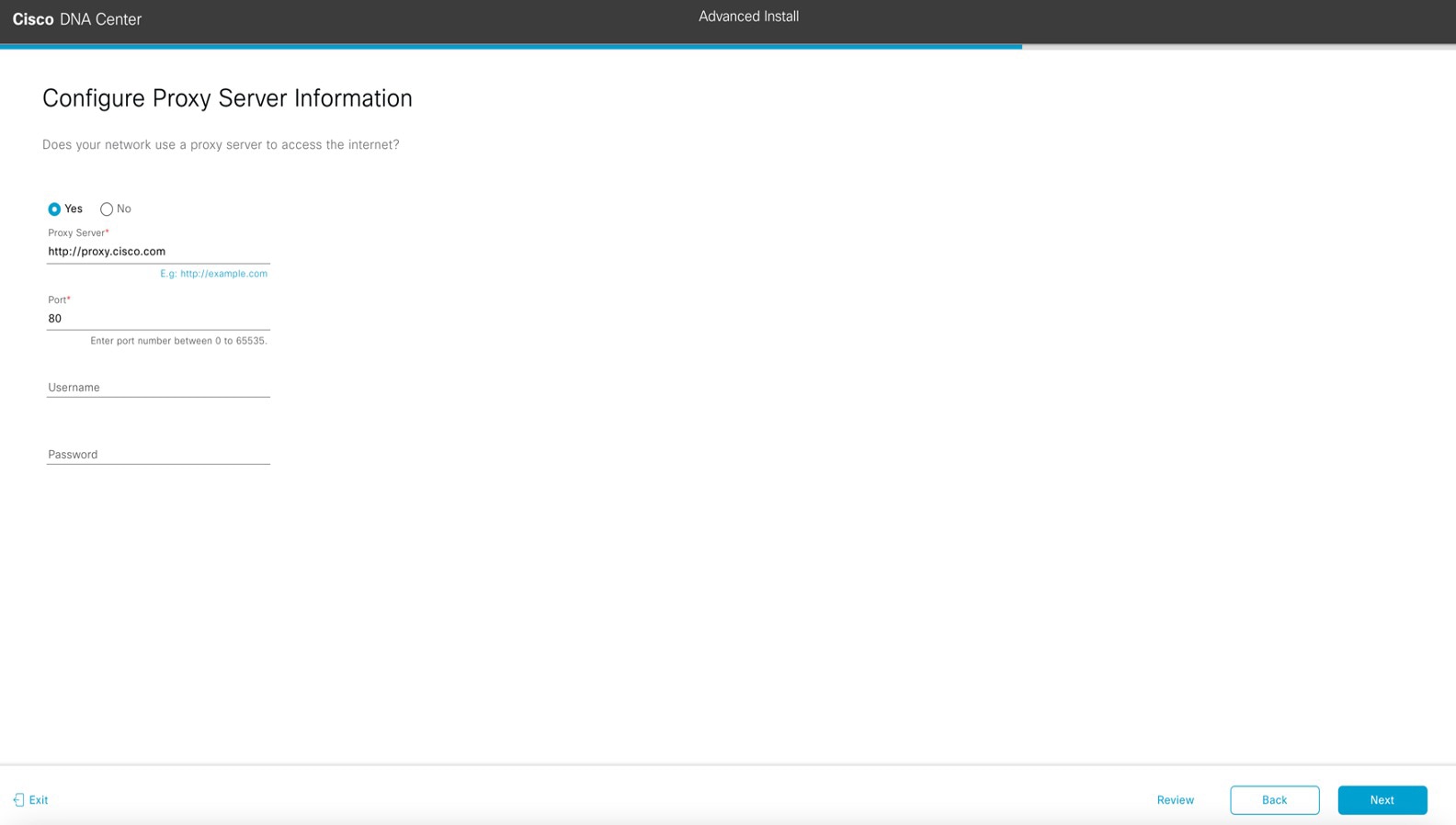
-
Do one of the following:
-
If your network does not use a proxy server to access the internet, click the No radio button and then click Next.
-
If your network does use a proxy server to access the internet, enter the values described in the following table:
Table 7. Primary Node Entries for Proxy Server Settings
|
Proxy Server field
|
Enter the URL or host name of an HTTPS network proxy used to access the Internet.
|
Note
|
Connection from Cisco DNA Center to the HTTPS proxy is supported only via HTTP in this release.
|
|
|
Port field
|
Enter the port your appliance used to access the network proxy.
|
|
Username field
|
Enter the user name used to access the network proxy. If no proxy login is required, leave this field blank.
|
|
Password field
|
Enter the password used to access the network proxy. If no proxy login is required, leave this field blank.
|
From here, do one of the following:
-
To close the wizard, click Exit. A popup window appears, indicating that the settings you have entered up to this point will be saved. Click Exit again to confirm that you want to close the wizard. When you restart the wizard and return to this screen, the settings that
you entered previously will already be populated.
-
To return to the previous wizard screen, click Back.
-
To proceed to the next wizard screen, click Next.
The wizard validates the information you have entered and notifies you of any settings that need to be changed before you
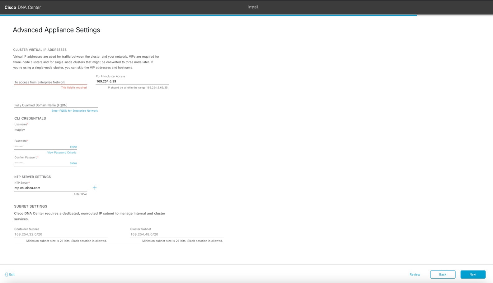
can proceed with the wizard. If the settings you have entered are valid and the port is up, the wizard's Advanced Appliance Settings screen opens.
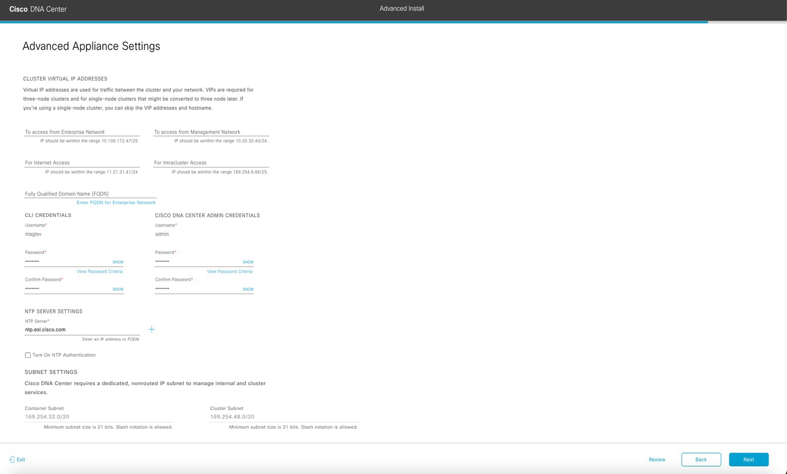
-
Enter configuration values for your cluster.
Table 8. Primary Node Entries for Advance Appliance Settings
|
Cluster Virtual IP Addresses
|
|
To access from Enterprise Network, To access from Management Network, For Internet Access, and For Intracluster Access fields
|
Note
|
If you configured the Management or Internet Access interface on the same port as the Enterprise interface, its corresponding
field is not displayed in this section.
|
|
Enter the virtual IP address that will be used for traffic between the cluster and the interfaces that you have configured
on your primary node. This is required for both three-node clusters and single-node clusters that will be converted into a
three-node cluster in the future. If you have a single-node cluster setup and don't plan to move to a three-node cluster setup,
you can leave the fields in this section blank.
|
Important
|
If you choose to configure a virtual IP address, you must enter one for each configured network interface. You will not be
able to complete the wizard unless you do so. These addresses are tied to the cluster link's status, which must be in the
UP state.
|
|
|
Fully Qualified Domain Name (FQDN) field
|
Enter the fully qualified domain name (FQDN) for your cluster. Cisco DNA Center does the following with this hostname:
-
It uses this hostname to access your cluster’s web interface and the Representational State Transfer (REST) APIs used by devices
in the enterprise network that Cisco DNA Center manages.
-
In the Subject Alternative Name (SAN) field of Cisco DNA Center certificates, it uses the FQDN to the define the Plug and Play server that should be used for device provisioning.
|
|
CLI Credentials
|
|
Password and Confirm Password fields
|
Enter and then confirm the password for the maglev user.
|
|
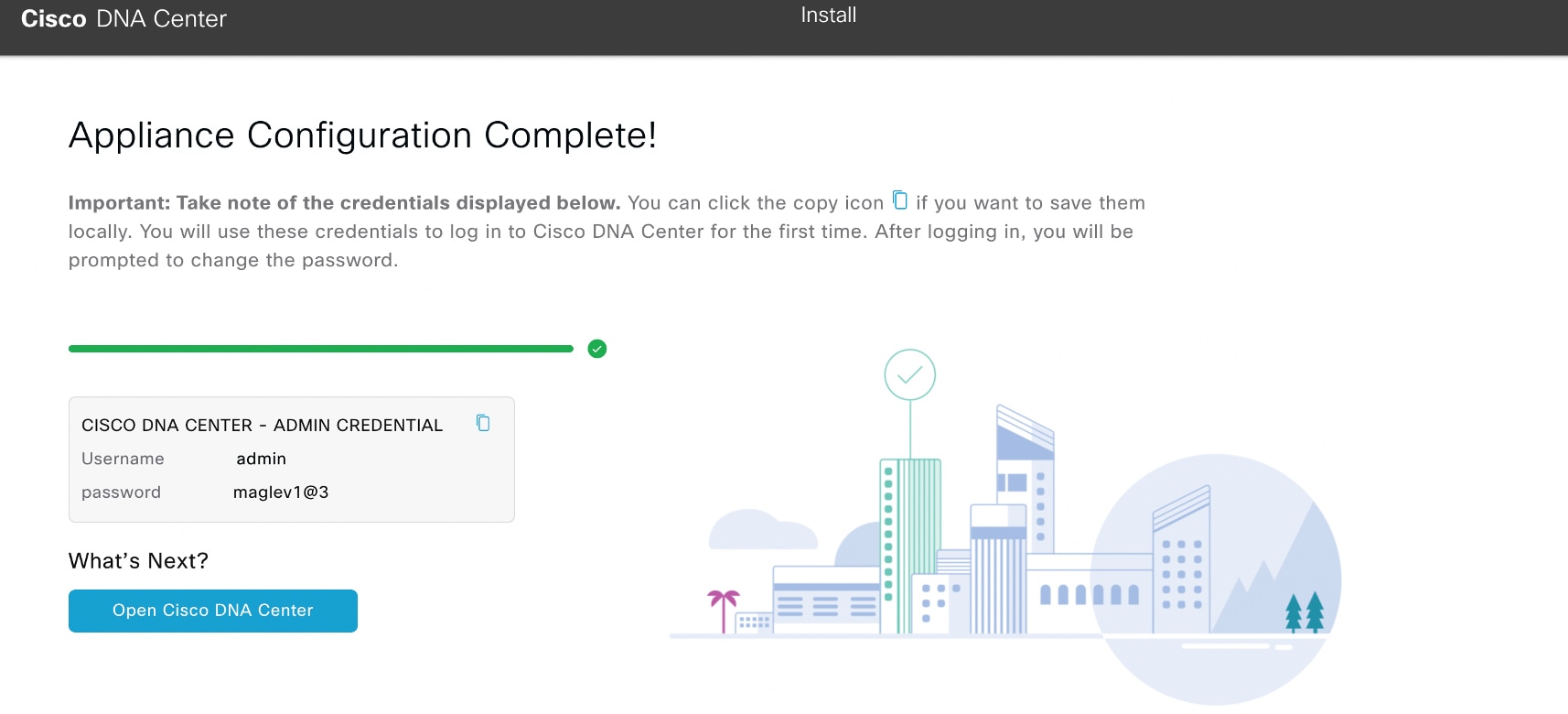
Cisco DNA Center Admin Credentials
|
|
Password and Confirm Password fields
|
Enter and then confirm the password for the default admin superuser, used to log in to Cisco DNA Center for the first time.
|
|
NTP Server Settings
|
|
NTP Server field
|
Enter at least one NTP server address or hostname. To enter additional NTP server addresses or hostnames, click the Add (+) icon.
For a production deployment, Cisco recommends that you configure a minimum of three NTP servers.
|
|
Turn On NTP Authentication check box
|
To enable the authentication of your NTP server before it's synchronized with Cisco DNA Center, check this check box and then enter the following information:
-
The NTP server's key ID. Valid values range between 1 and 4294967295 (2^32-1).
This value corresponds to the key ID that's defined in the NTP server's key file.
-
The SHA-1 key value associated with the NTP server's key ID. This 40-character hex string resides in the NTP server's key
file.
|
Note
|
Ensure that you enter a key ID and key value for each NTP server that you configured in the previous field.
|
|
|
Subnet Settings
|
|
Container Subnet field
|
A dedicated, non-routed IP subnet that Cisco DNA Center uses to manage internal services. By default, this is already set to 169.254.32.0/20, and we recommend that you use this subnet.
|
|
Cluster Subnet field
|
A dedicated, non-routed IP subnet that Cisco DNA Center uses to manage internal cluster services. By default, this is already set to 169.254.48.0/20, and we recommend that you use this subnet.
|
From here, do one of the following:
-
To close the wizard, click Exit. A popup window appears, indicating that the settings you have entered up to this point will be saved. Click Exit again to confirm that you want to close the wizard. When you restart the wizard and return to this screen, the settings that
you entered previously will already be populated.
-
To return to the previous wizard screen, click Back.
-
To proceed to the next wizard screen, click Next.
The wizard validates the information you have entered and notifies you of any settings that need to be changed before you
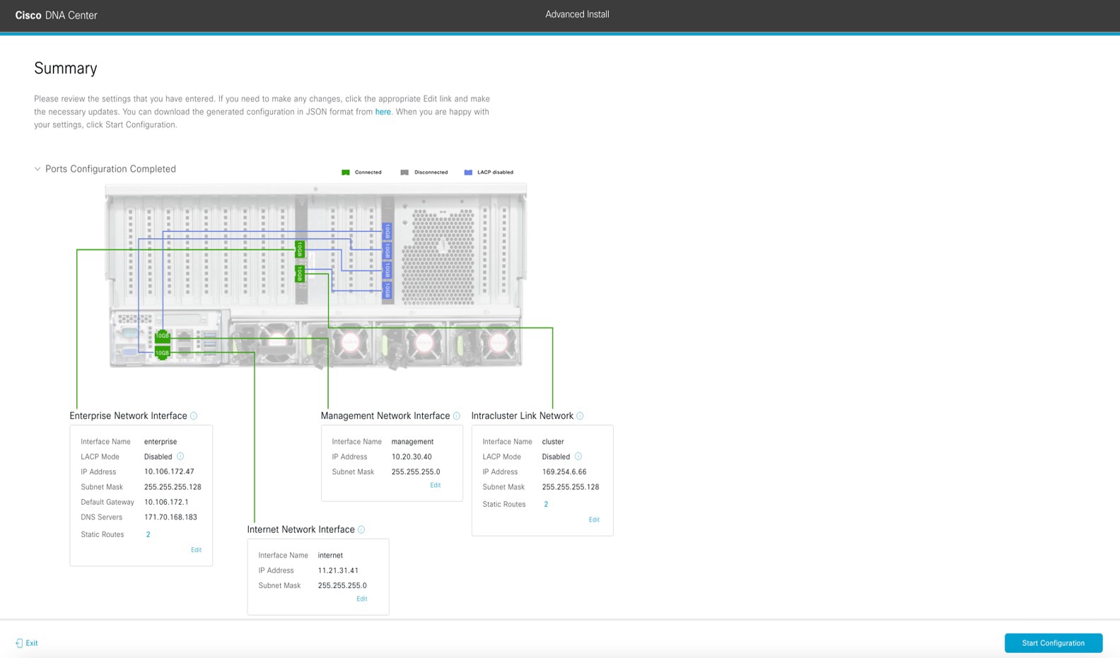
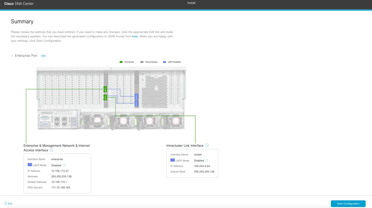
can proceed with the wizard. If the settings you have entered are valid, the wizard's Summary screen opens.
|
Note
|
To download the appliance configuration as a JSON file, click the here link.
|
-
Review all of the settings that you have entered while completing the wizard. If necessary, click the appropriate Edit link to open the wizard screen in which you want to make updates.
-
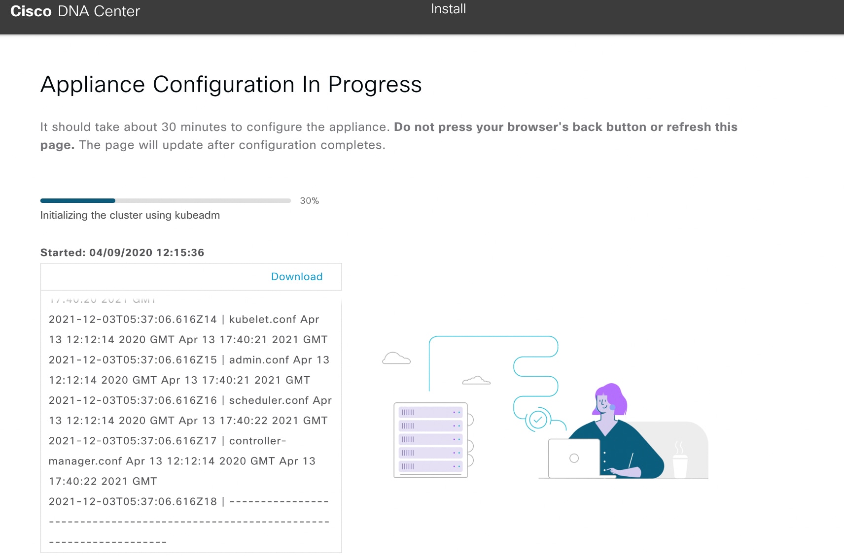
To complete the configuration of your Cisco DNA Center appliance, click Start Configuration.
The configuration process takes roughly 90 minutes. The wizard screen continuously updates during the process, indicating
the tasks that are currently being completed and their progress, as well as any errors that have occurred. To save a local
copy of this information as a text file, click the download icon.

|


 ) and choosing
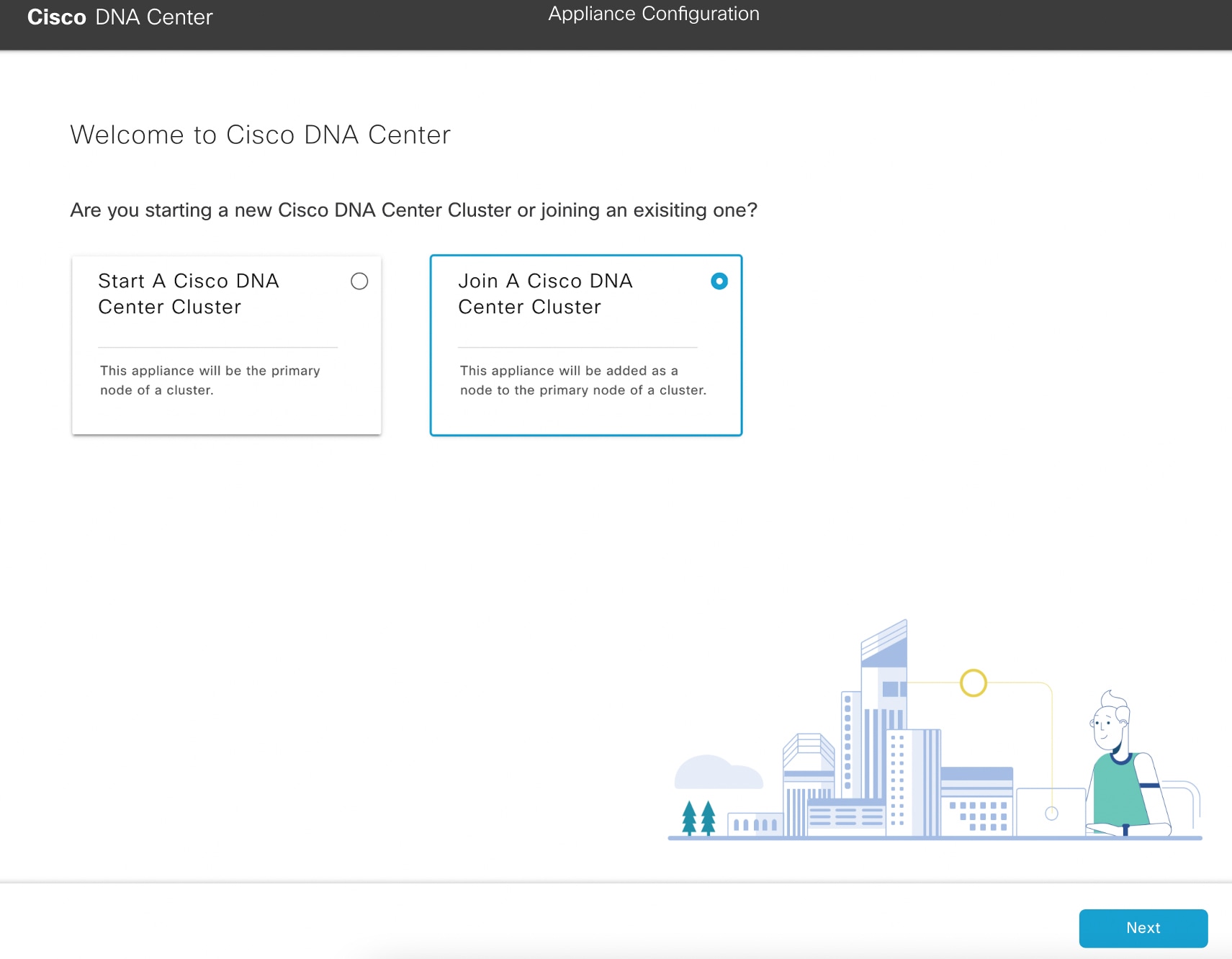


 Feedback