Features
The Cisco® Provider Connectivity Assurance Sensor F100 (formerly Accedian Skylight Flex 100 Performance Element) is a next-generation, multiport, 100 Gigabit Ethernet platform with ultra-low-latency packet forwarding and jitter.
Designed for high-bandwidth and high-availability applications requiring MEF-type service assurance, the Provider Connectivity Assurance Sensor F100 is optimized for scalable service delivery and high-precision, granular, real-time performance monitoring. It is an ideal edge, aggregation, or External Network-to-Network Interface (ENNI) unit for demanding high-bandwidth wireless backhaul, SLA-backed business services, Ethernet wholesale, and dark fiber termination applications.
The Assurance Sensor F100 provides all the tools to establish, validate, and monitor Layer 2 and Layer 3 services in a single unit. Zero-touch provisioning and IPv4/IPv6 management make these performance elements easy and secure to deploy and manage.
Fully integrated with the Cisco Provider Connectivity Assurance platform, it supports service delivery automation and scalable, real-time metrics collection and reporting—plus actionable insights delivery and machine learning for accelerated service rollout and improved operational efficiencies.
The Assurance Sensor F100 interoperates with other Provider Connectivity Assurance Sensors to deliver a scalable end-to-end and core-to-edge performance-assured networking solution tailored to your applications.

The following table lists the features of the Assurance Sensor F100.
|
Feature |
Description |
|---|---|
|
Form factor |
1RU |
|
Rack mount |
Standard 19-inch (48.3 cm) or 23-inch (58.42 cm) rack |
|
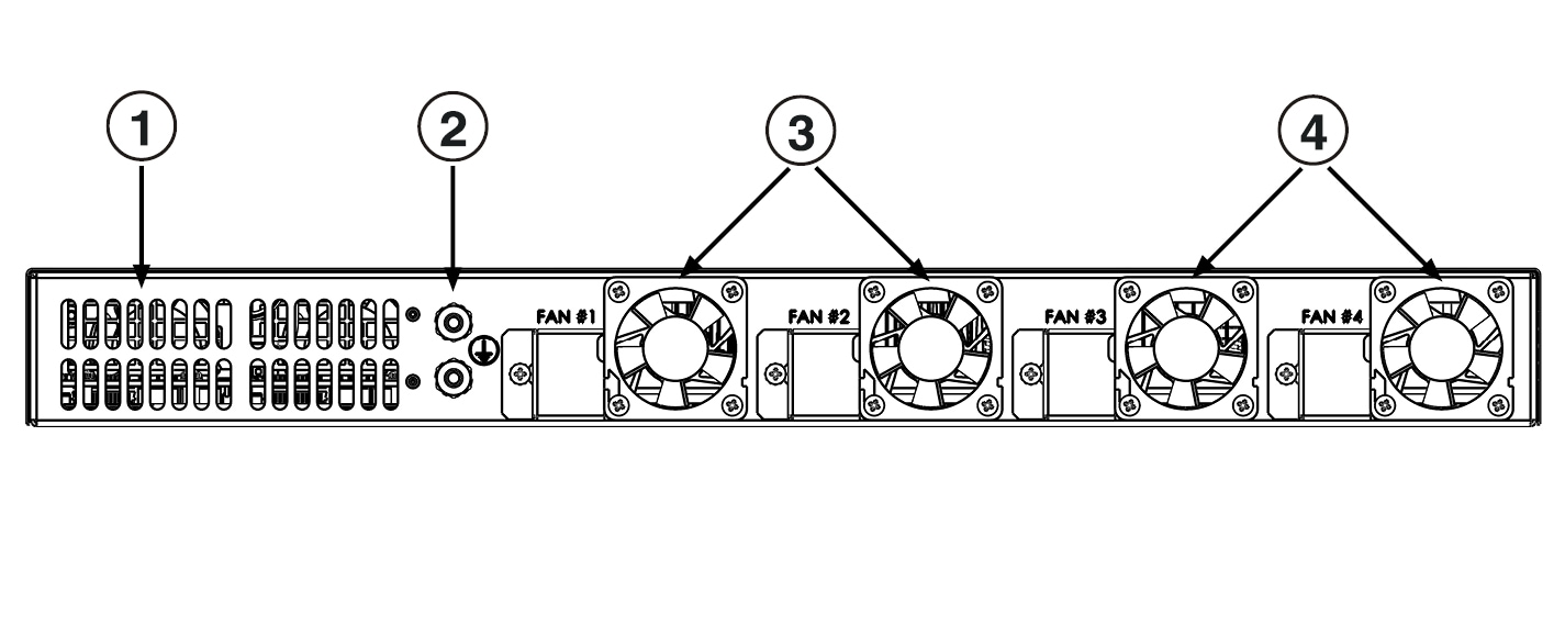
Airflow |
Front to rear |
|
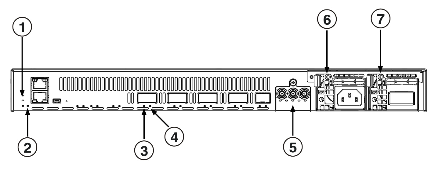
Management port |
Built-in One RJ-45 connector (10/100/1000 BASE-T) |
|
USB port |
One USB Mini-B console port (USB 2.0) |
|
Network ports |
Four QSFP28 connectors (100GBASE-R) |
|
Auxiliary port |
One SFP+ connector (10GBASE-R) |
|
Serial console port |
One RJ-45 serial connector (RS-232 or two dry contacts) |
|
Fans |
Four fans for front-to-rear cooling |
The following table lists the regulation and standard compliance features of the Assurance Sensor F100.
|
Feature |
Description |
|---|---|
|
Safety |
IEC 62368-1, EN 62368-1, UL 62368-1, CSA C22.2 No. 62368-1, AS/NZS 62368.1, J62368-1, CEI EN 62368-1, DS/EN 62368-1, SASO-IEC-62368-1 |
|
EMC - Emission (Class A) |
CISPR 32, IEC 61000-3-2, IEC 61000-3-3, EN 55032, EN 61000-3-2, EN 61000-3-3, 47 CFR Part 15 Subpart B, ICES-003, AS/NZS CISPR 32, VCCI-CISPR 32, KS C 9832 |
|
EMC - Immunity |
CISPR 35, EN 55035, KS C 9835 |
|
Telco |
NEBS Level-3: GR-63, GR-1089 |
| Radio |
ETSI EN 301 489-19, ETSI EN 303 413 |
|
Enviro |
RoHS: IEC 63000:2016,EN IEC 63000:2018 |


 Feedback