Mount the Chassis

Unpack and Inspect the Chassis


Note


The chassis is thoroughly inspected before shipment. If any damage occurred during transportation or any items are missing, contact your customer service representative immediately. Keep the shipping container in case you need to send the chassis back due to damage.

See Package Contents for a list of what shipped with the chassis.


Warning


You must install the unit in a restricted access location in the following cases:

  • If you are using a DC power connection and the ambient temperature is more than 50°C.

  • If you are using a centralized DC power connection.


Procedure


Step 1

Remove the chassis from its cardboard container and save all packaging material.

Step 2

Compare the shipment to the equipment list provided by your customer service representative. Verify that you have all items.

Step 3

Check for damage and report any discrepancies or damage to your customer service representative. Have the following information ready:

  • Invoice number of shipper (see the packing slip)

  • Model and serial number of the damaged unit

  • Description of damage

  • Effect of damage on the installation


Wall-Mount the Chassis

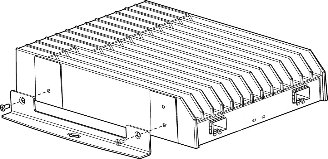
Secure the Wallmount Kit to both sides of the Module using the provided screws.

Figure 1. Secure the Wallmount Kit

When mounting a Module on a wall:

  • The support surface and the fasteners you use must support at least 6 kg (13.25 lbs).

  • Cable pull—accidental or otherwise—should not exceed the 4.5 kg (10 lbs) limit.

Rack-Mount the Chassis


Warning


Only the standard mounting brackets are NEBS compliant. The recessed brackets are not NEBS compliant.

To conform to the NEBS Seismic Zone 4 requirements, the bracket must be secured, using screws specified by the rack manufacturer, to a NEBS Seismic Zone 4 compliant rack. Such screws are not provided with the bracket kit.


To rack-mount the chassis:

Procedure


Step 1

Secure two L-shaped mounting brackets vertically to both sides of each Module using the provided screws.

Figure 2. Secure the L-shaped Mounting Brackets

Step 2

Carefully slide each Module into the rack-mount bracket with its heat sink facing upward. The rack-mount bracket may provide up to three bays.

Step 3

Align the L-shaped brackets with the pre-drilled holes and secure each Module to the rack-mount bracket.

Figure 3. Align the L-shaped Brackets

Step 4

Secure the rack-mount bracket to the rack using the fasteners as recommended by the manufacturer.


Ground the Chassis


Note


Statement 7013—Equipment Grounding Systems—Common Bonding Network (CBN)

This equipment is suitable for installations using the CBN.


Note


Statement 8016—Installation Location Where the National Electric Code (NEC) Applies

This equipment is suitable for installation in locations where the NEC applies.


Warning


For optimal performance, connect the functional ground screw to a suitable grounding point before applying power.