Cisco ACI with VMware vRealize

This chapter contains the following sections:

About Cisco ACI with VMware vRealize

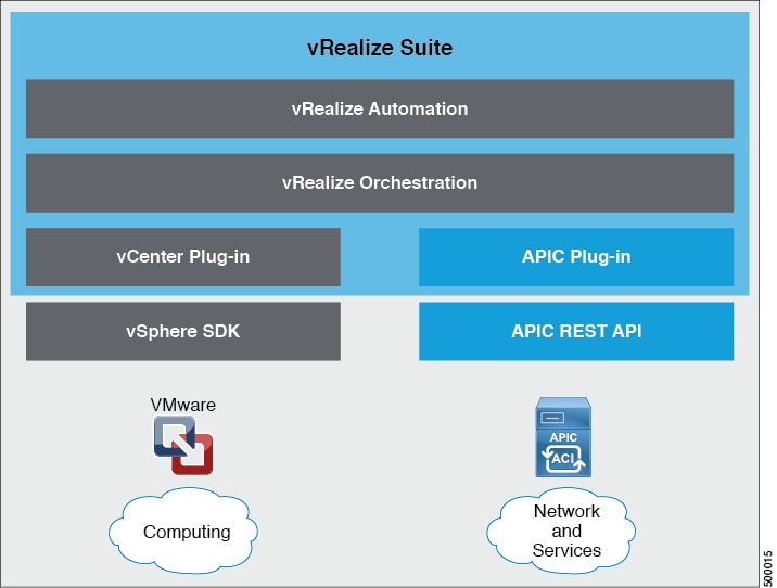
Cisco Application Centric Infrastructure (ACI), in addition to integrating with VMware vCenter, integrates with VMware's products vRealize Automation (vRA) and vRealize Orchestrator (vRO). vRA and vRO are parts of the VMware vRealize Suite for building and managing multivendor hybrid cloud environments.

Beginning with Cisco APIC Release 3.1(1), vRA and vRO support Cisco Application Centric Infrastructure (ACI) Virtual Edge (Cisco ACI Virtual Edge) in addition to VMware DVS.

This chapter discusses about vRealize Automation, Release 7.x. For details about Cisco ACI and VMware vRealize Automation, Release 8.x integration, see the Cisco ACI vRealize 8 Plug-in Guide.


Note


Beginning with Cisco Application Policy Infrastructure Controller (APIC) Release 5.0(1), Cisco Application Virtual Switch (AVS) is no longer supported. If you use Cisco AVS and upgrade to Cisco APIC Release 5.0(1), in case of issues, the fabric will not be supported. Also, a fault will be raised for the Cisco AVS domain.


Cisco ACI with VMware vRealize Solution Overview

vRA integration is delivered through a set of service blueprints imported into vRA. The service blueprints leverage the vRO Application Policy Infrastructure Controller (APIC) workflows, providing a set of catalog items in a self-service portal that allows Tenants to build, manage, and remove networking components. Multi-machine with ACI workflows achieve following functionalities:

  • Auto-create Tenant Endpoint Groups (EPGs)

  • Required policies in APIC

  • Create VMs and portgroups in vCenter

  • Auto-place the VMs is respective port groups

  • Created by APIC

  • Create security policy with access lists

  • Configure L4-L7 services, and provide external connectivity

This consumption model allows users to deploy single and multi-tier application workloads in single click with pre-defined as well as customizable compute and network policies. Catalog items are published by infrastructure administrators, whereby granular entitlements can be added or removed on a per-tenant basis.

The integration offers two modes of networking:

Mode

Description

Shared

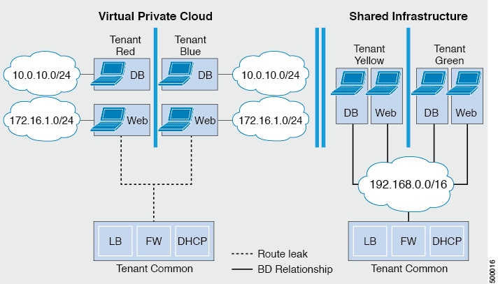
Shared mode is for Tenants who do not have a preference for what IP address space they use and a shared address space with shared context (VRF) is used across tenants. Isolation is provided using ACI Endpoint Groups (EPGs) and connectivity among EPGs are enabled using a white listing method.

Virtual Private Cloud (VPC)

VPC mode is a bring your own address space architecture, where network connectivity is isolated via a unique context (VRF) per tenant and external connectivity is provided via a common shared L3 out.

Physical and Logical Topology

This section shows the logical model of the vRealize ACI Integration and comparison between a Shared Services Plan and Virtual Private Cloud Plan.

Figure 1. This figure shows a logical model of the vRealize ACI Integration.


Figure 2. This figure shows the comparison between a Shared Services Plan and Virtual Private Cloud Plan.


For details, see the Cisco APIC Basic Configuration Guide.

About the Mapping of ACI Constructs in VMware vRealize

This table shows the mapping between the features of Cisco ACI policy and vRealize policy

Cisco ACI

VMware vRealize

Tenant

Tenant

EPGs

Networks

Layer 3 external connectivity

External routed network

Contract

Security policy

Filter

Rule entry list

L4-L7 service device

Shared load balancer or firewall

This list provides details regarding the features:

  • Tenant—Tenants can be employees within an organization, business units, application owners, or applications. Or if you are a service provider, they can be hosting customers (individuals or organizations that pay you to provide IT services).

  • Networks—In Cisco ACI, the term “network” refers to EPGs, which are used to provide a new model for mapping applications to the network. Rather than using forwarding constructs, such as addresses or VLANs, to apply connectivity and policy, EPGs use a grouping of application endpoints. EPGs are mapped to networks in the vRealize portal. The isolated networks act as containers for collections of applications, or of application components and tiers, that can be used to apply forwarding and policy logic. They allow the separation of network policy, security, and forwarding from addressing and instead apply these to logical application boundaries. When a network is created in vRealize, in the back end it is created as a port group in vCenter. A vRealize tenant can use vCenter to manage the computing resources and can attach the virtual machine to the appropriate network.

  • Layer 3 external connectivity—The Cisco ACI fabric connects to the outside through Layer 3 external networks. These constructs are also available for vRealize tenants to access other services within the data center, across the data center, or on the internet.

  • Security policy—Cisco ACI is built on a highly secure model, in which traffic between EPGs (isolated networks) is denied, unless explicitly allowed by policy contracts. A Cisco ACI contract is mapped to a security policy in the vRealize portal. The security policy describes which networks (EPGs) will provide and consume a service. The security policy contains one or more rule entry lists (filters), stateless firewall rules that describe a set of Layer 4 TCP or User Datagram Protocol (UDP) port numbers that define the communication between the various applications.

  • Shared load balancer and firewall—Cisco ACI treats services as an integral part of an application. Any services that are required are managed as a service graph that is instantiated on the Application Policy Infrastructure Controller (APIC) . Users define the service for the application, and service graphs identify the set of network and service functions that are needed by the application. Cisco ACI has an open ecosystem of L4-7 service vendors whose services integrate natively with Cisco ACI. This integration is achieved through device packages written and owned by the vendors. The APIC manages the network services and inserts the services according to the Cisco ACI policy model. For vRealize, Cisco ACI offers F5 and Citrix load balancers and Cisco ASA firewalls, both in virtual and physical form factors, which are connected to the Cisco ACI fabric and shared across the various vRealize tenants. After the device has been integrated into Cisco ACI, the vRealize administrator can choose to add the device as a premium service and upsell the plan. The vRealize administrator manages the virtual IP address range for the shared device, to simplify the vRealize tenant’s workflow.

  • VPC plan—In a VPC plan, vRealize tenants can define their own address spaces, bring a DHCP server, and map their address spaces to networks. A VPC tenant can also be offered services, such as load balancing, from the shared service plan. In this scenario, a device would have multiple virtual NICs (vNICs). One vNIC would connect to the private address space, and another would connect to the shared service infrastructure. The vNIC that connects to the shared service infrastructure would have an address assigned by the infrastructure and would also consume a shared load balancer owned by the infrastructure.

Event Broker VM Customization

vRealize Automation Event Broker is a workflow subscription service for vRealize Automation to call workflows from the vRealize Orchestrator under predefined conditions the user sets. It is supported beginning with Cisco APIC 3.0(1).

A deployment of a single or multitier application is automatically subscribed to the Event Broker. Machine operations such as creation or deletion on any machine, configured by the vRA, trigger the Event Broker. This invokes the preconfigured operations to the Cisco APIC defined by the Property Groups associated to a single or multitier application.

To add the Cisco APIC workflow subscription, follow the instructions at Setting Up the VMware vRealize Automation Appliance for ACI. The workflow subscription then will be added automatically.

Getting Started with Cisco ACI with VMware vRealize

This section describes how to get started with Cisco ACI with VMware vRealize.

You must download and unzip the Cisco ACI and VMware vRealize file for the 2.2(1) release before installing Cisco ACI with VMware vRealize.

Procedure


Step 1

Go to Cisco's Application Policy Infrastructure Controller (APIC) Website:

http://www.cisco.com/c/en/us/support/cloud-systems-management/application-policy-infrastructure-controller-apic/tsd-products-support-series-home.html

Step 2

Choose All Downloads for this Product.

Step 3

Choose the release version and the apic-vrealize-2.2.1x.tgz file.

Step 4

Click Download.

Step 5

Unzip the apic-vrealize-2.2.1x.tgz file.

Note


Cisco ACI with VMware vRealize only supports ASCII characters. Non-ASCII characters are not supported.


Prerequisites for Getting Started with Cisco ACI with VMware vRealize

Before you get started, ensure that you have verified that your vRealize computing environment meets the following prerequisites:

  • vRealize Automation(vRA) Release 7.0-7.4 must be installed.

    See VMware's vRealize documentation.

    It is highly recommended to use vRA 8.x. For details about vRA 8.x integration with Cisco ACI, see the Cisco ACI vRealize 8 Plug-in Guide.

  • The vRealize ACI plug-in version and the Cisco APIC version must match.

  • A tenant is configured in vRealize automation and associated with identity store. The tenant must have one or more users configured with "Infra Admin", "Tenant Admin", and "Tenant user" roles.

    See VMware's vRealize documentation.

  • The tenant must have one more "Business group" configured.

    See VMware's vRealize documentation.

  • Configure vRealize Orchestrator as an end-point.

    See VMware's vRealize documentation.

  • Configure vCenter as an endpoint.

    See VMware's vRealize documentation.

  • Configure "Reservations" using the vCenter compute resources.

    See VMware's vRealize documentation.

  • Set up the vRealize Appliance.

    See VMware's vRealize documentation.

  • If Layer 3 (L3) Out policies are to be consumed by a tenant, you must configure a BGP route reflector.

    See the Cisco APIC Basic Configuration Guide about Configuring an MP-BGP Route Reflector Using the Basic GUI or Configuring an MP-BGP Route Reflector.

  • Setup a vRA handle in vRO.

    This is used for Installing the ACI service catalog workflow.

  • Setup a IAAS handle in vRO.

    This is used for Installing the ACI service catalog workflow.

    See Setting Up an IaaS Handle in vRealize Orchestrator.

  • Install the vCAC/vRA Custom Property Toolkit for vCO/vRO. You can download the package from the following URL:

    https://communities.vmware.com/docs/DOC-26693

  • The embedded vRO in vRA has the vCAC vRO plug-in that is installed by default. If you are using a standalone vRO, the vCAC vRO plug-in must be installed. You can download the plug-in from the following URL:

    https://solutionexchange.vmware.com/store/products/vmware-vrealize-orchestrator-plug-in-for-vra-6-2-0

Setting Up an IaaS Handle in vRealize Orchestrator

This section describes how to set up an Infrastructure as a Service (IaaS) handle in the vRealize Orchestrator (vRO).

Procedure

Step 1

Log in to the VMware vRealize Orchestrator as administrator.

Step 2

Once the VMware vRealize Ochestrator GUI appears, from the drop-down list, choose Run from the menu bar.

Step 3

In the navigation pane, choose the Workflows icon.

Step 4

Choose Adminstrator@vra_name > Library > vRealize Automation > Configuration > Add the IaaS host of a vRA host.

Step 5

Right-click Add the IaaS host of a vRA host and choose Start Workflow.

Step 6

In the Start Workflow: Add the IaaS host of a vRA host dialog box, perform the following actions:

  1. In the vRA host field, enter your vRealize Handle.

  2. Click Next.

Step 7

In the next screen, perform the following actions:

  1. In the Host Name field, enter a name.

  2. In the Host URL field, enter the URL of your IaaS host.

  3. Use the default values for the remaining fields.

  4. Click Next.

Step 8

In the next screen, perform the following actions:

  1. In the Session mode drop-down list, choose Shared Session.

  2. In the Authentication user name field, enter the authentication user name.

  3. In the Authentication password field, enter the password.

  4. Click Next.

Step 9

In the next screen, perform the following actions:

  1. In the Workstation for NTLM authentication field, enter the name of the workstation that you will use for NTLM authentication.

  2. In the Domain for NTLM authentication field, enter the domain that is used in the IaaS host URL.

  3. Click Submit.


Cisco ACI with VMware vRealize Installation Workflow

This section describes the Cisco ACI with VMware vRealize installation workflow.

Procedure


Step 1

Install the APIC plug-in on the vRealize Orchestrator (vRO).

For more information, see Installing the APIC Plug-in on the vRealize Orchestrator.

Step 2

Set up the VMware vRealize Automation Appliance for ACI.

For more information, see Setting Up the VMware vRealize Automation Appliance for ACI.


Installing the APIC Plug-in on the vRealize Orchestrator

This section describes how to install APIC plug-in on the vRealize Orchestrator.

Procedure

Step 1

Once you have unzipped the package, save the aci-vra-plugin-3.0.1000.N.dar file in a known directory.

Step 2

Log in to the vRA appliance as root using SSH, enter:

$ ssh root@<vra_ip>

Step 3

Start the configurator to enable the configurator services web interface, enter the following commands:

# service vco-configurator start
.
.
.
Tomcat started.
Status:           Running as PID=15178

Ensure the status is running.

Step 4

Log in to the VMware appliance using the Firefox browser, enter:

https://applicance_address:8283/vco-controlcenter

Note


Cisco recommends using the Firefox browser.

Do not use the Internet Explorer or the Chrome browser for the first time. There is a known issue when you use the default username and password. It does not login properly.

For more information, see https://communities.vmware.com/thread/491785.

  1. In the VMware vRealize Orchestrator Configuration GUI, enter the default username and password which is vmware/vmware. You will then be required to change the password.

Step 5

Under the Plug-Ins section, click Manage Plug-Ins.

Step 6

Under Install plug-in, click the Browse... button and perform the following steps:

  1. Locate where you saved the aci-vra-plugin-3.0.1000.N.dar file and choose the aci-vra-plugin-3.0.1000.N.dar file.

  2. Click Install on the right, and when the Cisco APIC Plug-in displays, click Install again.

    • A message highlighted in green displays, saying that the plug-in is installed.

    • A message highlighted in yellow displays, saying "The Orchestrator server must be restarted for the changes to take effect. The restart can be performed from the Startup Options page."

Step 7

Click Startup Options.

You will be directed to the Startup Options page.

Step 8

Click Restart to restart the server. Wait until the Current Status displays RUNNING.

Step 9

Navigate back to the Manage Plug-Ins page by clicking Home on the top left and then clicking Manage Plug-Ins under the Plug-Ins section.

Step 10

Verify the Cisco APIC plug-in has been installed by looking for it under Plug-Ins.

The plug-in will be displayed first with the Cisco icon.


Setting Up the VMware vRealize Automation Appliance for ACI

This section describes how to set up the VMware vRealize Automation Appliance for Cisco ACI.

Procedure

Step 1

Log in to the VMware vRealize Automation Appliance as the administrator through your tenant portal using the browser:

https://applicance_address/vcac/org/tenant_id

Example:

https://192.168.0.10/vcac/org/tenant1

Enter the admin username and password.

Step 2

In the VMware vRealize Automation Appliance GUI, perform the following actions:

  1. Choose Administration > Users & Groups > Custom Groups

  2. In the Custom Group pane, click Add to add a custom group.

  3. Enter the name of the custom group. (Service Architect)

  4. In the Roles to this group field, select the custom group you created in the previous step. (Service Architect)

  5. Choose the Member pane, enter and select the user name(s).

  6. Click Add.

    This creates a custom group with members.
  7. In the Custom Group pane, choose the custom group you created. (Service Architect)

  8. In the Edit Group pane, you can verify the members in the Members pane.

Step 3

In the browser, enter the vRealize Automation Appliance.

https://applicance_address

For example:

https://vra3-app.ascisco.net

  1. Choose the vRealize Orchestrator Client to download the client.jnlp file.

  2. The Downloads dialog box will appear, launch the client.jnlp file.

Step 4

Log in to the VMware vRealize Orchestrator as administrator.

Step 5

Once the VMware vRealize Orchestrator GUI appears, from the drop-down list, choose Run from the menu bar.

Step 6

In the Navigation pane, choose the Workflows icon.

Step 7

Choose Adminstrator@vra3-app.ascisco.net > Cisco APIC Workflows > Utils > Install ACI Service Catalog.

Step 8

Right-click Install ACI Service Catalog and choose Start Workflow.

Step 9

In the Start Workflow - Install ACI Service Catalog dialog box, perform the following actions:

  1. In the APIC Hostname/IP Address field, enter the APIC hostname or IP address.

  2. In the APIC Admin Password field, enter the APIC admin password.

  3. In the vRealize Automation IP Address field, provide the IP address for the vRA.

  4. In the vRealize Automation handle field, click Not set, navigate and choose the vRealize automation handle for this appliance.

  5. In the Business group field, click Not set to choose business group.

    Note

     
    If running vRealize 7.0, you need to select the Business Group from Business Group (Deprecated).

    Note

     
    Usernames need to include the domain name. For example: admin1@vsphere.local
  6. In the Admin User field, enter the tenant admin user.

  7. In the vRealize Automation Admin Password field, enter the admin password for the vRA.

  8. In the End users field, click Not set and enter the user names to enable privilege for.

    Note

     
    Do not copy and paste the end user names, you should type the user names.
  9. In the JSON File containing vRealize Properties field, click Not set, navigate and choose the JSON file containing the vRealize properties. (aci-vra-properties-3.0.1000.x.json)

    Note

     
    Usernames need to include the domain name. For example: admin1@vsphere.local
  10. In the Zip file containing the service blueprints field, click Not set, navigate and choose the zip file containing the service blueprints. (aci-vra-asd-3.0.1000.x.zip)

  11. Click Submit.

Step 10

In the Navigation pane, you will see a green check mark next to the Install ACI Service Catalog, if the installation was successful.

Step 11

In the Navigation pane, choose the Workflows icon.

Step 12

Right-click Install ACI Property Definitions and choose Start Workflow.

Step 13

In the Start Workflow - Install ACI Property Definitions dialog box, click Net set, navigate and choose the IaaS host.

  1. Click Submit.

    In the Navigation pane, you will see a green checkmark next to the Install ACI Property Definitions, if the installation was successful.

Step 14

To verify as a tenant, log in to the vRealize Automation Appliance as tenant, choose Catalog and you will see the services.

Step 15

To verify as an administrator, log in to the vRealize Automation Appliance as administrator, choose Catalog and you will see the services.

  1. Choose Infrastructure > Blueprints > Property Definitions and you will see the properties.


Day-0 Operations of ACI

This section describes day-0 operations of ACI.

Before you begin
  • Fabric bring-up

    Bring up the fabric and all topologies are supported.

  • Access policies

    • Attach Entity Policy (AEP)

    • Configure access policies between the leaf switches and ESXi hosts to ensure CDP and LLDP is enabled between the leaf and host.

  • Layer 3 (L3) Out configuration

    • Create any L3 Out configurations in the common tenant that you wish to be consumed user tenants.

    • You can choose any name for the L3 policy.

    • External EPG must be named "[L3OutName|InstP]".

    • Create two policies.

      For shared plan, specify "default" and for VPC plan, specify "vpcDefault".

      For more information, see About L3 External Connectivity.

  • Service graph templates and devices

    Create any service graph devices in the common tenant.

    For more information, see Configuring the Services on APIC Using XML POST.

  • Security domains and tenant user

    • vRealize plug-in requires two user accounts.

      The first account needs administrator privileges. This account allows you to create, read, update, and destroy objects in the tenant common, access policies, and VMM domains.

      The second account needs restricted tenant privileges. This account allows you to only read common tenant and VMM domains, but you can create, read, update, and destroy objects in their own tenant.

    • Role-based access control (RBAC) rules are enforced through the APIC not the plug-in.

Procedure

See the Cisco APIC Basic Configuration Guide for more information.


Associating AEP with VMware VMM Domain

This section describes how to associate an attachable entity profile (AEP) with VMware VMM domain.


Note


You do not need to perform this procedure if the domain type is Cisco AVS.
Procedure

Step 1

Log in to the APIC GUI, and then choose Fabric > Access Policies.

Step 2

In the navigation pane, expand Policies > Global > Attachable Access Entity Profiles and then click the profile.

Step 3

In the work pane, perform the following actions:

  1. In the Domains (VMM, Physical or External) Associated to Interfaces field, click the + to expand.

  2. In the unformed field, choose a VMM domain and click Update.


Cisco ACI with VMware vRealize Upgrade Workflow

This section describes the Cisco ACI with VMware vRealize upgrade workflow.

Procedure


Step 1

Upgrade the APIC image.

Step 2

Upgrade the APIC plug-in on the vRealize Orchestrator (vRO).

For more information, see Upgrading the APIC Plug-in on the vRealize Orchestrator.

Step 3

Set Up the VMware vRealize Automation Appliance for ACI.

For more information, see Setting Up the VMware vRealize Automation Appliance for ACI.

Step 4

Verify the connection between APIC and vRealize.

For more information, see Verifying the Connection Between APIC and vRealize.


Verifying the Connection Between APIC and vRealize

After you have upgraded the Application Policy Infrastructure Controller (APIC) controller and the switch software, you must verify the connection from the vRealize Orchestrator to APIC.

Before you begin

  • Ensure the APIC controller and the switch software is upgraded.

    For more information, see the Cisco ACI Firmware Management Guide.

Procedure


Step 1

Log in to the vRealize Orchestrator as administrator.

Step 2

In the navigation pane, choose the Inventory icon.

Step 3

Expand the Cisco APIC Plugin, choose the APIC and check the following:

  1. In the General pane, check if the controllers are showing in the Name field.

  2. Check if you can maneuver through the nested hierarchy below the APIC. This ensures you are communicating with APIC.

    If the connection from vRO to APIC is not established, then next to the APIC name the string down will be present, indicating that the connection is down.


Cisco ACI with VMware vRealize Downgrade Workflow

This section describes the Cisco ACI with VMware vRealize downgrade workflow.

Procedure


Step 1

Downgrade the APIC image.

Step 2

Delete the APIC plug-in package and all the APIC workflows.

For more information, see Deleting Package and Workflows.

Step 3

Install the APIC plug-in on the vRealize Orchestrator (vRO).

For more information, see Upgrading the APIC Plug-in on the vRealize Orchestrator.

Step 4

Set up the VMware vRealize Automation Appliance for ACI.

For more information, see Setting Up the VMware vRealize Automation Appliance for ACI.

Step 5

Verify the connection between APIC and vRealize.

For more information, see Verifying the Connection Between APIC and vRealize.


Deleting Package and Workflows

This section describes how to delete the package and workflows.

Procedure


Step 1

Log in to the vRO client as administrator.

Step 2

Choose the Design role.

Step 3

Choose the Packages tab.

Step 4

Right-click on the com.cisco.apic.package and choose Delete element with content.

Step 5

Choose Keep Shared in the pop-up window.

Step 6

Choose the Workflows tab.

Step 7

Ensure that all workflows in the "Cisco APIC workflows" folder and subfolders are deleted.

To delete the workflow: Select the workflow, right-click and choose Delete.


Use Case Scenarios for the Administrator and Tenant Experience

This section describes use case scenarios for the administrator and tenant experience.

Overview of Tier Application Deployment

This section describes the overview of 3-tier application deployment.

Deployment of a single-tier application using property groups

See Deploying a Single-Tier Application Using Property Groups.

Deployment of a 3-tier application using a multi-machine blueprint

See Deploying a 3-Tier Application Using a Multi-Machine Blueprint.

Deploying a Single-Tier Application Using Property Groups

This section describes how to deploy a single-tier application using property groups.

Procedure

Step 1

Connect to the vRealize Automation appliance by pointing your browser to the following URL:

https://appliance_address/vcac/org/tenant_id

Step 2

Enter the tenant administrator username and password.

Step 3

Choose Catalog.

Step 4

Click Configure Property Groups.

You will configure the database tier.

Step 5

Click Request.

Step 6

In the Request Information tab, enter a description of the request.

Step 7

Click Next.

Step 8

In the Common tab, perform the following actions:

  1. In the IaaS Host for vRealize field, click Add.

  2. Put a check in the box next to the desired IaaS host.

  3. Click Submit.

  4. In the APIC Tenant field, click Add.

  5. Expand apic_name > Tenants.

  6. Put a check in the box next to the desired tenant's name.

    Example:

    green
  7. Click Submit.

  8. In the Property Group Name field, enter a name for the property group.

    Example:

    green-app-bp
  9. In the Plan Type (Shared or VPC) field, click Shared.

  10. In the VMM Domain/DVS field, click Add.

  11. Expand apic_name > Vcenters > vcenter_name

  12. Put a check in the box next to the desired vCenter's name.

    Example:

    green
  13. Click Submit.

Step 9

Click Next.

Step 10

In the VM Networking tab, leave all of the fields at their default values.

Step 11

Click Next.

Step 12

In the Security tab, perform the following actions:

  1. In the Configure Security Policy drop-down list, choose No.

Step 13

In the Load Balancer tab, from the drop-down list, choose No.

Step 14

In the Firewall tab, from the drop-down list, choose No.

Step 15

Click Submit.

Step 16

Click OK.

Step 17

To verify your request, choose the Requests tab.

  1. Choose the request you submitted and click view details. Ensure the status is Succesful.

Step 18

(Optional) To edit a blueprint in the property group, choose Infrastructure > Blueprints > Property Groups.

  1. In the Property Group pane, choose the property group you created (green-app-bp) and click edit.

  2. In the Edit Property Group pane, choose the property group you want to edit and click on the pencil icon to edit a certain blueprint.

  3. Once you have completed your edits, click OK.

Step 19

Attach the property group to the VMs, choose Infrastructure > Blueprints.

Step 20

In the Blueprints pane, click New Blueprint, from the drop-down list, choose Virtual > vSphere (vCenter).

Step 21

In the New Blueprint vSphere (vCenter)pane, perform the following actions:

  1. In the Blueprint Information tab, enter the information to create your blueprint and click OK. See VMware's documentation for details on how to create your machine blueprint.

  2. In the Build Information tab, enter the information to create your property group and click OK. See VMware's documentation for details on how to create your machine blueprint.

Step 22

In the Properties tab, perform the following actions:

  1. In the Property Groups field, choose your property group that you created (green-app-bp) and click OK.

  2. Click on the magnifying glass icon for the newly created property group (green-app-bp).

  3. In the Property Group Custom Properties dialog box, ensure that the properties match your property group and this makes a connection with the VM and the ACI networking.

  4. In the New Blueprint vSphere (vCenter)pane, click OK.

Step 23

In the Blueprints pane, perform the following actions:

  1. Choose your property group that you created (green-app-bp), hover and choose Publish.

  2. Click OK.

  3. Choose Aministration > Catalog Management > Catalog Items.

Step 24

In the Catalog Items pane, perform the following actions.

  1. Find and choose the blueprint that you created (Green App Tier).

Step 25

In the Configure Catalog Item pane, perform the following actions.

  1. In the Details tab, in the Service field, choose VM Services.

  2. Check the check box for New and noteworthy.

  3. Click Update.

You now have deployed a single-tier application using property groups.

Step 26

To verify the deployment of the single-tier application, log out of the administrator session and log back in as the tenant.

  1. Click the Catalog tab.

  2. In the navigation pane, choose VM Services.

  3. In the Work pane, choose the blueprint you created.

  4. In the Catalog Item Details pane, verify the properties of the blueprint and click Request.

  5. In the New Request pane, click Submit and then OK.

This provisions a new virtual machine, ACI networking, and connects the two together.

Deploying a 3-Tier Application Using a Multi-Machine Blueprint

VMware vRealize multi-machine blueprints are groupings of one or more machine blueprints to be deployed simultaneously. A common use case is a three-tier web application, where the web, app, and database tiers are deployed together. From a networking perspective, you must push the application policy into Cisco Application Centric Infrastructure (ACI) to enable secure communication between tiers that need to communicate. This is achieved by creating a security policy and associating the relevant machines dynamically at deployment time.

When configuring a blueprint that will be used in a multi-machine blueprint, a security policy must be created. During the creation process, the consumer and provider must be provided. The provider is always the machine that you are building, and the consumer can be any other machine or network.

As an example, say that you have a MySQL database machine blueprint that provides a service on port 3306. The application tier machines need to access this database, but the web tier machines do not. Under the Security Policy section of the Configure Property Group workflow, you create a policy with the "app" tier as the consumer, listing port 3306 as permissible (everything else is denied by default) and the blueprint will automatically place the "db" tier as the provider.

The "app" tier also must provide a service; in this example a server is listening on port 8000. The web tier will then consume this service. The security policy must be specified in the "app" tier property group.


Note


Machine prefixes generate a unique name for each virtual machine that is deployed. An example prefix for a tenant named "Green" could be "green-web-", plus three unique digits for each machine. The sequence would be: "green-web-001", "green-web-002", "green-web-003", and so on. It is important that you follow a similar scheme with your machine prefixes so that the Application Policy Infrastructure Controller (APIC) plug-in can accurately predict the name of the consumer endpoint group. Additionally, every machine must be on the same prefix number. For example, the names for a 3-tier app must be: green-db-001, green-app-001, and green-web-001. If any tier were not aligned, the security policy would fail to form a correct relationship. This is a requirement because vRealize does not provide the name of the sibling tiers, so the plug-in must infer the siblings' names based on its own name.

When configuring a security policy under a property group, the consumer name should be the second word of the machine prefix. For the example prefix "green-web-", the consumer name would be "web".


This section describes how to deploy a 3-tier application using a multi-machine blueprint.

Procedure

Step 1

Connect to the vRealize Automation appliance by pointing your browser to the following URL:

https://appliance_address/vcac/org/tenant_id

Step 2

Enter the tenant administrator username and password.

Step 3

Choose Catalog.

Step 4

Click Configure Property Group.

You will configure the database tier.

Step 5

Click Request.

Step 6

In the Request Information tab, enter a description of the request.

Step 7

Click Next.

Step 8

In the Common tab, perform the following actions:

  1. In the IaaS Host for vRealize field, click Add.

  2. Put a check in the box next to the desired IaaS host.

  3. Click Submit.

  4. In the APIC Tenant field, click Add.

  5. Expand apic_name > Tenants.

  6. Put a check in the box next to the desired tenant's name.

    Example:

    green
  7. Click Submit.

  8. In the Property Group Name field, enter a name for the property group.

    Example:

    green-db-mm
  9. In the VMM Domain/DVS field, click Add.

  10. Expand apic_name > Vcenters > vcenter_name

  11. Put a check in the box next to the desired vCenter's name.

    Example:

    green
  12. Click Submit.

Step 9

Click Next.

Step 10

In the VM Networking tab, leave all of the fields at their default values.

Step 11

Click Next.

Step 12

In the Security tab, perform the following actions:

  1. In the Configure Security Policy drop-down list, choose Yes.

  2. In the Consumer Network/EPG Name of Security Policy field, enter the name of the consumer network, without the full machine prefix.

    Example:

    app

    The database tier must have the application tier as the consumer.

  3. In the Starting Port Number in Security Policy field, enter the starting port number.

    Example:

    3306
  4. In the Ending Port Number in Security Policy field, enter the ending port number.

    Example:

    3306
  5. For the other fields, leave their values at the defaults.

Step 13

Click Next.

Step 14

In the Load Balancer tab, leave the field at its default value.

Step 15

Click Next.

Step 16

In the Firewall tab, leave the field at its default value.

Step 17

Click Submit.

Step 18

Click OK.

Step 19

Click Configure Property Group.

This time, you will configure the application tier.

Step 20

Click Request.

Step 21

In the Request Information tab, enter a description of the request.

Step 22

Click Next.

Step 23

In the Common tab, perform the following actions:

  1. In the IaaS Host for vRealize field, click Add.

  2. Put a check in the box next to the desired IaaS host.

  3. Click Submit.

  4. In the APIC Tenant field, click Add.

  5. Expand apic_name > Tenants.

  6. Put a check in the box next to the desired tenant's name.

    Example:

    green
  7. Click Submit.

  8. In the Property Group Name field, enter a name for the property group.

    Example:

    green-app-mm
  9. In the VMM Domain/DVS field, click Add.

  10. Expand apic_name > Vcenters > vcenter_name

  11. Put a check in the box next to the desired vCenter's name.

    Example:

    green
  12. Click Submit.

Step 24

Click Next.

Step 25

In the VM Networking tab, leave all of the fields at their default values.

Step 26

Click Next.

Step 27

In the Security tab, perform the following actions:

  1. In the Configure Security Policy drop-down list, choose Yes.

  2. In the Consumer Network/EPG Name of Security Policy field, enter the name of the consumer network, without the full machine prefix.

    Example:

    web

    The application tier must have the web tier as the consumer.

  3. In the Starting Port Number in Security Policy field, enter the starting port number.

    Example:

    8000
  4. In the Ending Port Number in Security Policy field, enter the ending port number.

    Example:

    8000
  5. For the other fields, leave their values at the defaults.

Step 28

Click Next.

Step 29

In the Load Balancer tab, leave the field at its default value.

Step 30

Click Next.

Step 31

In the Firewall tab, leave the field at its default value.

Step 32

Click Submit.

Step 33

Click OK.

Step 34

Click Configure Property Group.

You will configure the web tier.

Step 35

Click Request.

Step 36

In the Request Information tab, enter a description of the request.

Step 37

Click Next.

Step 38

In the Common tab, perform the following actions:

  1. In the IaaS Host for vRealize field, click Add.

  2. Put a check in the box next to the desired IaaS host.

  3. Click Submit.

  4. In the APIC Tenant field, click Add.

  5. Expand apic_name > Tenants.

  6. Put a check in the box next to the desired tenant's name.

    Example:

    green
  7. Click Submit.

  8. In the Property Group Name field, enter a name for the property group.

    Example:

    green-web-mm
  9. In the VMM Domain/DVS field, click Add.

  10. Expand apic_name > Vcenters > vcenter_name

  11. Put a check in the box next to the desired vCenter's name.

    Example:

    green
  12. Click Submit.

Step 39

Click Next.

Step 40

In the VM Networking tab, leave all of the fields at their default values.

Step 41

Click Next.

Step 42

In the Security tab, leave the field at its default value.

Because this is a consumer policy, you do not need to configure the security policy.

Step 43

Click Next.

Step 44

In the Load Balancer tab, leave the field at its default value.

Step 45

Click Next.

Step 46

In the Firewall tab, leave the field at its default value.

Step 47

Click Submit.

Step 48

Click OK.


About Plan Types

The administrator creates the plan with their own values. The plan types are as follows:

Shared Infrastructure

Virtual Private Cloud (VPC)

Isolated Networks

Yes

Yes

Firewall

Yes

Yes

Provider DHCP

Yes

Yes

Shared Load Balancer

Yes

Yes

Public Internet Access

Yes

Yes

Shared Services between Tenants

Yes

Yes

Bring your own address space (Private Address Space) and DHCP Server

No

Yes

About vRealize Service Categories and Catalog Items

This section describes the vRealize services categories and catalog items. The list of all catalog items they are grouped into services and each of these services are assigned an entitlement. ACI entitlement is assigned to certain users.

For more information, see ACI Administrator Services in vRealize.

For more information, see ACI Tenant Services in vRealize.

For more information, see Entitlements for ACI catalog-items in vRealize.

Mapping of the ACI Plan Types to vRealize Service Categories

This section shows the mapping of the Cisco ACI plan types to vRealize service categories.

Figure 3. vRA - User, Entitlements, Services and Blueprints


vRA Catalog Category

List of Blueprints

Admin service blueprints

Add APIC with Admin credentials
Add APIC with Tenant credentials
Add Provider for Shared Service (Contract)
Add or Update Tenant
Add VIP Pool
Add VMM Domain, AVS Local Switching with Vlan Encap
Add VMM Domain, AVS Local Switching with Vxlan Encap
Add VMM Domain, AVS No Local Switching
Add VMM Domain, AVE Local Switching with Vlan Encap
Add VMM Domain, AVE Local Switching with Vxlan Encap
Add VMM Domain, AVE No Local Switching
Add VMM Domain, DVS and Vlan Pool
Add or Delete Bridge Domain in Tenant-common
Add or Delete Consumer for Shared Service (Contract)
Add or Delete L3 context (VRF) in Tenant-common
Add or Delete Router Id
Add or Delete Subnets in Bridge Domain for Tenant-Common
Update FW Policy (DFW) association to AVS or AVE VMM Domain
Configure Property Group
Create FW Policy (DFW) and Associate to AVS or AVE VMM Domain
Delete APIC
Delete FW Policy (DFW)
Delete Provider Shared Service (Contract)
Delete Tenant
Delete VIP Pool
Delete VMM Domain, AVS or AVE, and VLAN, Multicast Pool
Delete VMM Domain, DVS and Vlan Pool
Generate and Add Certificate to APIC
Rest API
Update FW Policy (DFW) AVS or AVE
Update Vlan Pool, AVS or AVE
Update Multicast Pool, AVS
Update VMM Domain DVS security domain mapping
Update AVS or AVE VMM Domain Security Domain Mapping

Tenant Shared Plan service blueprints

Add a Useg Network - Shared Plan
Add FW and LB to Tenant Network - Shared Plan
Add FW to Tenant Network - Shared Plan
Add Loadbalancer to Tenant Network - Shared plan
Add Tenant Network - Shared plan
Delete a Useg Network - Shared Plan
Delete FW and LB from Tenant Network - Shared Plan
Delete FW from Tenant Network - Shared Plan
Delete Loadbalancer from Tenant Network - Shared Plan
Delete Tenant Network - Shared plan

Tenant VPC Plan service blueprints

Add a Useg Network - VPC Plan
Add FW and LB to Tenant Network - VPC Plan
Add FW to Tenant Network - VPC Plan
Add Loadbalancer to Tenant Network - VPC plan
Add Tenant Network - VPC plan
Delete a Useg Network - VPC Plan
Delete FW and LB from Tenant Network - VPC Plan
Delete Loadbalancer from Tenant Network - VPC Plan
Delete Tenant Network - VPC  plan

Network Security service blueprints

Add Security Policy (Contracts)
Delete Security Policy (Contracts)
Update Access List Security Rules

Tenant Network Service blueprints

Add or Delete Bridge domain in Tenant
Add or Delete L3 Context (VRF) in Tenant
Add or Delete Subnets in Bridge domain
Add or Delete Useg Attribute
Attach or Detach L3 external connectivity to Network
Update Tenant Network

ACI Administrator Services in vRealize

This section describes the ACI Administrator Services in vRealize.

List of Admin Services Catalog Items for ACI Administrator Services

This section provides a list of the admin services catalog items for ACI administrator services.

Catalog Item

Description

Add APIC with Tenant Credentials

This creates the Application Policy Infrastructure Controller (APIC) handle with tenant credentials.

Add APIC with Admin Credentials

This creates the APIC handle with Admin credentials.

Add or Delete Bridge Domain in Tenant-common

This adds or deletes the bridge domain in tenant-common.

Add or Delete Consumer for Shared Service (Contract)

This adds or deletes consumer for shared service (Contract).

Add or Delete L3 context (VRF) in Tenant-common

This adds or deletes Layer 3 context (VRF) in tenant-common.

Add or Delete Subnets in Bridge Domain for Tenant-Common

This adds or deletes subnets in the bridge domain for tenant-common.

Add Provider for Shared Service (Contract)

This adds provider for shared service (Contract).

Add or Delete Router Id

This adds or deletes the router Id.

Add or Update Tenant

This adds or updates a tenant.

If the tenant wants to use the Firewall between EPGs, set "Enable inter-EPG Firewall" to Yes. Also the number application tiers should be set. To use typical 3-tier web, app, db application the number of tiers should be set to 3.

Add VIP Pool

This adds the Virtual IP Pool.

Configure Property Group

This configures the property group.

Delete APIC

This deletes the APIC.

Delete Provider Shared Service (Contract)

This deletes the provider shared service (Contract).

Delete Tenant

This deletes a tenant.

Delete VIP Pool

This deletes the Virtual IP Pool.

Generate and Add Certificate to APIC

This blueprints can be used to generate a certificate for a given user. This certificate then be used in the certificate based access to APIC.

REST API

This is the REST API.

This section provides a list of the admin services catalog items for ACI administrator services for the VMM domain type DVS.

Catalog Item

Description

Add VMM Domain, DVS and VLAN Pool

This adds VMM Domain, DVS, and VLAN Pool.

Ensure all hosts of the data-center that has the APIC created DVS in vCenter, must have at least one physical NIC attached. This ensures that the port-groups of the DVS are available for virtual NIC placements.

Delete VMM Domain, DVS, and VLAN Pool

This deletes the VMM Domain, DVS and VLAN Pool.

Update Vlan Pool (encap blocks)

This updates the Vlan Pool (encap blocks).

Update VMM Domain DVS security domain mapping

This updates the VMM Domain DVS security domain mapping.

This section provides a list of the admin services catalog items for ACI administrator services for the VMM domain type Cisco AVS or Cisco ACI Virtual Edge (AVE).


Note


Beginning with Cisco APIC Release 5.0(1), Cisco Application Virtual Switch (AVS) is no longer supported. If you use Cisco AVS and upgrade to Cisco APIC Release 5.0(1), in case of issues, the fabric will not be supported. Also, a fault will be raised for the Cisco AVS domain.

If you use Cisco AVS, we recommend that you migrate to Cisco ACI Virtual Edge. See the Cisco ACI Virtual Edge Installation Guide on Cisco.com.


Catalog Item

Description

Add VMM Domain, AVS or AVE Local Switching with Vlan Encap

This creates a VMM domain in Cisco APIC with VLAN as the default encapsulation mode. It also creates a VLAN pool and multicast address pool (in the case of mixed mode). This item also creates an associated Cisco AVS or Cisco ACI Virtual Edge with local switching in vCenter.

Add VMM Domain, AVS or AVE Local Switching with Vxlan Encap

This creates a VMM domain in Cisco APIC with VXLAN as the default encapsulation mode. It also creates a multicast address pool and VLAN pool (in the case of mixed mode). This item also creates an associated Cisco AVS or Cisco ACI Virtual Edge with local switching in vCenter.

Add VMM Domain, AVS or AVE No Local Switching

This adds VMM domain, multicast address pool in Cisco APIC and creates an associated Cisco AVS or Cisco ACI Virtual Edge with no local switching in vCenter.

Update Multicast Pool, AVS or AVE

This updates the multicast pool for Cisco AVS or Cisco ACI Virtual Edge VMM domain.

Update VLAN Pool, AVS or AVE

This updates the VLAN pool for the Cisco AVS or Cisco ACI Virtual Edge VMM domain.

Update AVS or AVE VMM Domain Security Domain Mapping

This updates the security domain mapping of the Cisco AVS or Cisco ACI Virtual Edge VMM domain.

Delete VMM Domain AVS or AVE, Vlan, Multicast Pool

This deletes the Cisco AVS or Cisco ACI Virtual Edge VMM Domain and VLAN Pools and Multicast Pool in Cisco APIC and deletes the associated Cisco AVS or Cisco ACI Virtual Edge in vCenter.

Create FW Policy (DFW) and Associate to AVS or AVE VMM Domain

This creates a Distributed Firewall policy and associates it to the Cisco AVS or Cisco ACI Virtual Edge VMM domain.

Update FW Policy (DFW) association to AVS or AVE VMM Domain

This associates/dissociates an existing Distributed Firewall policy to the Cisco AVS or Cisco ACI Virtual Edge VMM domain.

Update FW Policy (DFW)

This updates the existing Distributed Firewall Policy.

Delete FW Policy (DFW)

This deletes the existing Distributed Firewall Policy.

To submit a request:

  1. Log in to the vRealize Automation as admin, choose Catalog > Admin Services.

  2. Choose a request, enter the information in the fields and click Submit.

To view your request:

  1. In the vRealize Automation GUI, choose Requests.

  2. Choose the request you submitted and click view details.

ACI Tenant Services in vRealize

This section describes the ACI tenant services in the vRealize.

List of Network Security Catalog Items for ACI Tenant Services

This section provides a list of the Network Security catalog items for ACI tenant services.

Catalog Item

Description

Add Security Policy (Contracts)

This creates the security policy between tenant networks. For example: APIC contracts between consumer EPG and provider EPG.

Delete Security Policy (Contracts)

This deletes the security policy between tenant networks. For example: APIC contracts between consumer EPG and provider EPG.

Update Access List Security Rules

This adds or removes access list rules associated with a Security Policy Filter created in APIC (using Add Security Policy (Contracts)). The access list rules are of the format <source-port, destination-port, protocol, ethertype>.

Note


The Source and Dest Ports are not allowed for arp, icmp, icmpv6 rules. Ports are valid only for tcp and udp protocols. The access list rules are deployed and enforced in ACI fabric and they are stateless in nature.

In addition this blueprint also has an option to update the stateful firewall rules on a Firewall appliance such as Cisco-ASA for a specific service graph that is provided as an input.

To submit a request:

  1. Log in to the vRealize Automation as admin, choose Catalog > Network Security.

  2. Choose a request, enter the information in the fields and click Submit.

To view your request:

  1. In the vRealize Automation GUI, choose Requests.

  2. Choose the request you submitted and click view details.

List of Tenant Network Services Catalog Items for ACI Tenant Services

The following table lists the Tenant Network Services catalog items for ACI tenant services. You must log in to the tenant portal with tenant administrator privileges to execute the Tenant Network Services catalog items.

Catalog Item

Description

Add or Delete Bridge Domain in Tenant

This adds or deletes the bridge domain in tenant.

Add or Delete L3 Context (VRF) in Tenant

This adds or deletes Layer 3 context (VRF) in tenant.

Add or Delete Subnets in Bridge domain

This adds or deletes subnets in the bridge domain.

Attach or Detach L3 external connectivity to Network

This attaches or detaches Layer 3 external connectivity to the network.

Update Tenant Network

This updates the tenant network.

The following table lists the Tenant Network Services catalog items for VMM domain of type Cisco AVS and Cisco ACI Virtual Edge only. You must log in to the tenant portal with tenant administrator privileges to execute the Tenant Network Services catalog items.


Note


Beginning with Cisco APIC Release 5.0(1), Cisco Application Virtual Switch (AVS) is no longer supported. If you use Cisco AVS and upgrade to Cisco APIC Release 5.0(1), in case of issues, the fabric will not be supported. Also, a fault will be raised for the Cisco AVS domain.

If you use Cisco AVS, we recommend that you migrate to Cisco ACI Virtual Edge. See the Cisco ACI Virtual Edge Installation Guide on Cisco.com.


Catalog Item

Description

Add or Delete Useg Attribute

This adds or deletes an attribute for a microsegment EPG.

To submit a request:

  1. Log in to the vRealize Automation as tenant admin, choose Catalog > Tenant Network Services.

  2. Choose a request, enter the information in the fields and click Submit.

To view your request:

  1. In the vRealize Automation GUI, choose Requests.

  2. Choose the request you submitted and click view details.

List of Tenant Shared Plan Catalog Items for ACI Tenant Services

The following table lists the Tenant Shared Plan catalog items for ACI tenant services. You must log in to the tenant portal with tenant administrator privileges to execute the Tenant Shared Plan catalog items.

Catalog Items

Description

Add Tenant Network

This adds the tenant network in a shared plan.

Add FW and LB to Tenant Network - Shared Plan

This adds a firewall and load balancer to the tenant network in a shared plan.

Add FW to Tenant Network - Shared Plan

This adds a firewall to the tenant network in a shared plan.

Add Load Balancer to Tenant Network - Shared Plan

This adds load balancer to the tenant network in a shared plan.

Delete FW and LB from Tenant Network - Shared Plan

This deletes the firewall and load balancer from the tenant network in a shared plan.

Delete FW from Tenant Network - Shared Plan

This deletes the firewall from the tenant network in a shared plan.

Delete Load Balancer from Tenant Network - Shared Plan

This deletes load balancer from the tenant network in a shared plan.

Delete Tenant Network - Shared Plan

This deletes the tenant network in a shared plan.

The following table lists the Tenant Shared Plan catalog items for VMM domain of type Cisco AVS only. You must log in to the tenant portal with tenant administrator privileges to execute the Tenant Shared Plan catalog items.


Note


Beginning with Cisco APIC Release 5.0(1), Cisco Application Virtual Switch (AVS) is no longer supported. If you use Cisco AVS and upgrade to Cisco APIC Release 5.0(1), in case of issues, the fabric will not be supported. Also, a fault will be raised for the Cisco AVS domain.

If you use Cisco AVS, we recommend that you migrate to Cisco ACI Virtual Edge. See the Cisco ACI Virtual Edge Installation Guide on Cisco.com.


Catalog Item

Description

Add a Useg Network - Shared Plan

This adds a microsegment EPG in a shared plan.

Delete a Useg network - Shared Plan

This deletes a microsegment EPG in a shared plan.

To submit a request:

  1. Log in to the vRealize Automation as admin, choose Catalog > Tenant Shared Plan.

  2. Choose a request, enter the information in the fields and click Submit.

To view your request:

  1. In the vRealize Automation GUI, choose Requests.

  2. Choose the request you submitted and click view details.


Note


Symptom: You might see errors in the VMware vCenter during the deletion of the service graph through the vRealize Automation (vRA) workflow.

Condition: During the deletion of the service graph, if a port group is deleted before service devices such as VPX or F5 are configured, then these errors are seen. This sequence cannot be controlled through vRA.

Workaround: There is no workaround. These errors are transitory and will stop once the reconfiguration of the service devices is done.


List of Tenant VPC Plan Catalog Items for ACI Tenant Services

The following table lists the Tenant Virtual Private Cloud (VPC) Plan catalog items for ACI tenant services. You must log in to the tenant portal with tenant administrator privileges to execute the Tenant VPC Plan catalog items

Catalog Item

Description

Add Tenant Network - VPC Plan

This adds the tenant network in a VPC plan.

Add FW and LB to Tenant Network - VPC Plan

This adds the firewall and load balancer to the tenant network in a VPC plan.

Add FW to Tenant Network - VPC Plan

This adds the firewall to the tenant network in a VPC plan.

Add Load-balancer to Tenant Network - VPC Plan

This adds the load balancer to tenant network in a VPC plan.

Delete FW and LB from Tenant Network - VPC Plan

This deletes the firewall and load balancer from tenant network in a VPC plan.

Delete Load-balancer from Tenant Network - VPC Plan

This deletes load balancer from tenant network in a VPC plan.

Delete Tenant Network - VPC Plan

This deletes the tenant network in a VPC plan.

The following table lists the Tenant VPC Plan catalog items for VMM domain of type Cisco AVS or Cisco ACI Virtual Edge only. You must log in to the tenant portal with tenant administrator privileges to execute the Tenant VPC Plan catalog items.


Note


Beginning with Cisco APIC Release 5.0(1), Cisco Application Virtual Switch (AVS) is no longer supported. If you use Cisco AVS and upgrade to Cisco APIC Release 5.0(1), in case of issues, the fabric will not be supported. Also, a fault will be raised for the Cisco AVS domain.

If you use Cisco AVS, we recommend that you migrate to Cisco ACI Virtual Edge. See the Cisco ACI Virtual Edge Installation Guide on Cisco.com.


Catalog Item

Description

Add a Useg Network - VPC plan

This adds a microsegment EPG in a VPC plan.

Delete a Useg Network - VPC plan

This deletes a microsegment EPG in a VPC plan.

To submit a request:

  1. Log in to the vRealize Automation as admin, choose Catalog > Tenant VPC Plan.

  2. Choose a request, enter the information in the fields and click Submit.

To view your request:

  1. In the vRealize Automation GUI, choose Requests.

  2. Choose the request you submitted and click view details.

List of VM Services Catalog Items for ACI Tenant Services

This section provides a list of the VM services catalog items for ACI tenant services.

This service category has the tenant catalog items based on single machine and multi-machine blueprints. For example, for typical three tier application, it contains 3 catalog items "Web", "App", "Db" using single-machine blueprints and 1 catalog item "Web-App-Db" using multi-machine blueprint.

Catalog Item

Description

App

This is the application VM.

Db

This is the database VM.

Test

This is the single-machine VM blueprint for testing property groups.

Web

This is the web VM.

Web-Db-App

This multi-machine blueprint creates a 3-tier application, load balancer attached to the Web tier and the security policy configuration.

To submit a request:

  1. Log in to the vRealize Automation as admin, choose Catalog > VM Services.

  2. Choose a request, enter the information in the fields and click Submit.

To view your request:

  1. In the vRealize Automation GUI, choose Requests.

  2. Choose the request you submitted and click view details.

Entitlements for ACI catalog-items in vRealize

This section describes the entitlements for ACI catalog-items in vRealize. Each service category must have an entitlement. Entitlement enables the catalog items to be available for the users.

You can create and manage entitlements to control the access to the catalog items, actions, and specify the approval policies to apply the catalog requests. You can update the priority of the entitlement to determine which approval policy applies to a particular request.

List of Entitlements for ACI Catalog Items

This section provides a list of the entitlements for ACI catalog items.

Name

VMs Entitlements

Admin Entitlements

Tenant Shared Plan Entitlements

Tenant VPC Plan Entitlements

Common Network Services Entitlements

Tenant Network Services Entitlements

Tenant-common Network Services

Network Security Entitlements

To edit an entitlement:

  1. Log in to the vRealize Automation as admin, choose Administration > Catalog Management > Entitlements.

  2. Choose an entitlement to edit, enter the information in the fields and click Update.

ACI Plug-in in vRealize Orchestrator

The service category and the catalog item maps to a workflow.

APIC Workflows

These are the service categories and the catalog items and each catalog items is implemented as a workflow in the vRealize Orchestrator and the catalog items parameter are exactly same as the workflow parameters.

Service Categories

Description

Admin Services

Admin catalog-items to be executed by the global administrator

Network Security

Catalog-items for configuring security policies

Tenant Network Services

For configuring network services (bridge-domain, subnets)

Tenant Shared Plan

For configuring EPG/networks, microsegment EPGs, consuming load balancer, and firewall services in shared mode

Tenant VPC Plan

For configuring EPG/networks, microsegment EPGs, consuming load balancer, and firewall services in VPC mode

VM Services

Single-machine and multi-machine blueprints configured with ACI property groups

APIC Inventory View

In the Inventory view of the vRealize Orchestrator GUI, the Cisco APIC Plugin is a read only view. The Cisco APIC Plugin for vRealize Orchestrator maps to the APIC. For example, if you look at an object in the vRealize Orchestrator GUI it provides the MultiApicDn in the Cisco APIC GUI.

About Load Balancing and Firewall Services

VLAN, virtual routing and forwarding (VRF) stitching is supported by traditional service insertion models, the Application Policy Infrastructure Controller (APIC) can automate service insertion while acting as a central point of policy control. The APIC policies manage both the network fabric and services appliances. The APIC can configure the network automatically so that traffic flows through the services. The APIC can also automatically configure the service according to the application's requirements, which allows organizations to automate service insertion and eliminate the challenge of managing the complex techniques of traditional service insertion.

Perimeter Firewall is typically used to provide state-full firewall services for all incoming external traffic to the application. Once the traffic passes the firewall, another typical service that is inserted is the load balancing. The external traffic is sent towards, a virtual IP. The load balancer terminates this traffic and load balances the incoming traffic among the available servers (such as web servers) behind the load balancers.

See the Cisco APIC Layer 4 to Layer 7 Services Deployment Guide for more information.

APIC vRealize plug-in can be used to create new multi-tier applications while inserting the load balancer and/or firewall services for the traffic between them or it can be used to insert the firewall and load-balancer services for traffic between existing application end-point groups. For creating a multi-tier application with L4-7 services, a property group has to be created using "Configure Property Group" catalog-item in the "Admin Services". In addition of L4-7 services between existing application end-point groups can be done by choosing the appropriate catalog-item from the "Tenant Shared Services" items.


Note


In this release, only support for Shared-Plan is supported for Load balancer and Firewall services.


Prerequisites for Enabling Services

This section describes the prerequisites for enabling services.

You must perform the following tasks to deploy Layer 4 to Layer 7 services using the APIC vRealize plug-in:

  • Device package for load balancer needs to be uploaded by APIC admin.

    Use the link to download the required Citrix, F5, and Cisco ASA device packages:

    http://www.cisco.com/c/en/us/solutions/collateral/data-center-virtualization/application-centric-infrastructure/solution-overview-c22-734587.html

    Ensure the device package version is certified for the APIC release that you are using.

  • Device cluster for load balancer, firewall needs to be created in tenant "common" by APIC-admin. Citrix and F5 are the supported vendors for load balancers. Cisco ASA is the supported vendor for firewall.

  • For stand-alone firewall or load balancer service, a service graph template with single node must be configured. For the firewall and load balancer service, a service graph template with two nodes must be configured.

  • For the abstract service graph, the firewall node (vnsAbsNode) must be named FW, and the load balancer node must be named SLB.

  • For the load balancer only abstract service graph name (vnsAbsGraph) should be same as the load balancer device cluster (vnsLdevVip).

  • For the load balancer only service, the consumer L3 connectivity policy must be configured in the "default" VRF of the tenant common.

  • For the firewall, the consumer L3 connectivity policy must be configured in the separate VRF ("outside") of the tenant common.

  • The firewall device needs to be deployed in the routed mode. For firewall device connectivity, two additional L3 connectivity policy must be configured. One must be configured in the "outside" VRF, and is used as the external connection to the firewall device. The other must be configured in the "default" VRF and is used as the internal connection to the firewall device. These two L3 connectivity policies, attached to the firewall enables the firewall to do the VRF stitching and re-direct the traffic appropriately between the VRFs. The administrator has to ensure that appropriate prefixes with the correct import and export flags are configured under the L3 external connectivity policies.

  • The following convention should be used when configuring the L3 connectivity policies. For the L3 connectivity policy should be named as L3ExtName, the child L3 instance should be named as L3ExtNameInst.

  • The interface IP addresses that are used on the firewall and load balancer devices need to be configured in the abstract graph.

  • For the 2-node abstract graph, an access list to permit all traffic needs to be configured for the firewall node.

Configuring the Services on APIC Using XML POST

Only the administrator can configure and post the XML POST. The template POSTs are located in the apic-vrealize package under the services directory.

Before you begin
  • The device package file should be uploaded on the Application Policy Infrastructure Controller (APIC).

    See the Cisco APIC Layer 4 to Layer 7 Device Package Development Guide for more information.

  • The tenant common should have the two bridge domains named "default" and "vpcDefault". Ensure that the subnets being used by the tenant who is consuming the load balancer are added to these bridge domains. Typically you would have created these bridge domains and subnets while setting up the DHCP infrastructure for vRealize tenants.

  • For a non-Virtual Private Cloud (VPC) plan, the backend interface of the load balancer should be placed in the default EPG under the tenant common that was created above. For a VPC plan, the EPG should be "vpcDefault".

  • Ensure that the VIP subnet is linked with L3. One VIP per EPG will be allocated from the VIP pool associated with the tenant.

  • Prerequisites for the service scripts:

    • Python 2.7

    • Python libraries:

      • jinja2

      • yaml

      • glob

      • json

      • requests

      • xml

      • re

Procedure

Step 1

Use the following link to download the required device packages Citrix, F5, and ASA. Ensure that the device package version is certified for the APIC release that you are using. Store the device package zip files in this directory:

http://www.cisco.com/c/en/us/solutions/collateral/data-center-virtualization/application-centric-infrastructure/solution-overview-c22-734587.html

Step 2

Replace the VENDOR-DEVICE-PACKAGE.zip entries in the shared.cfg or vpc.cfg file with the correct device package files.

Step 3

Edit the setup.yaml file and change the variables to according to your setup.

The template variables in the setup.yaml file are:
TEMPLATE_VARS:     
    VCENTER: "vcenter1"
    ASA_IP: "1.1.1.1"
    ASA_CLUSTER: "AsaCluster1"
    ASA_VM: "asav-service5"
    OUTSIDE_CTX: "outside"
    INSIDE_CTX: "default"
    FW_GRAPH: "FWOnlyGraph"
    FW_SLB_GRAPH: "FWAndSLBGraph"
    BD_WEB: "default"
    CITRIX_MGMT_IP: "1.1.1.1"
    FW_NODE: "FW"
    SLB_NODE: "SLB"
    CITRIX_GRAPH: "CitrixCluster1_L3"
    CITRIX_CLUSTER: "CitrixCluster1_L3"
    CITRIX_GRAPH: "CitrixCluster1_L3"
    CITRIX_VM: "NS-service4"
    F5_BD: "F5Cluster1_L3"
    F5_EPG: "F5Cluster1_L3"
    F5_CLUSTER: "F5Cluster1_L3"
    F5_MGMT_IP: "1.1.1.1"
    F5_GRAPH: "F5Cluster1_L3"
    F5_ABS_NODE: "SLB"
    # Use deleted to generate the "deleted" version of the posts 
    # STATUS: "deleted"
    STATUS: ""

Step 4

Enter the following commands:

For Shared Plan:

Example:
../jinja.py setup.yaml tn-common-template.xml > tn-common.xml
../jinja.py setup.yaml Shared-Plan-Citrix-graph-template.xml > Shared-Plan-Citrix-graph.xml
../jinja.py setup.yaml Shared-Plan-F5-graph-template.xml > Shared-Plan-F5-graph.xml

For VPC Plan:

Example:
../jinja.py setup.yaml VPC-tn-common-template.xml > VPC-tn-common.xml
../jinja.py setup.yaml VPC-Plan-Citrix-LB-graph-template.xml > VPC-Plan-Citrix-LB-graph.xml
../jinja.py setup.yaml VPC-Plan-F5-LB-graph-template.xml > VPC-Plan-F5-LB-graph.xml

If you see python errors, ensure that the prerequisite python libraries are installed in the system.

Step 5

Edit the shared.cfg or vpc.cfg file and set the values for hosts: <YOUR_APIC_IP> and passwd: <YOUR_APIC_ADMIN_PASSWD>.

Sample of the shared.cfg file:

Example:
host:   <YOUR_APIC_IP>:443
name:   admin
passwd: <YOUR_APIC_ADMIN_PASSWD>
tests:
    - type: file
      path: /ppi/node/mo/.xml
#      file: asa-device-pkg-1.2.2.1.zip
#      Replace actual ASA Device package file in the line below
      file: ASA-DEVICE-PACKAGE.zip
      wait: 2
    - type: file
      path: /ppi/node/mo/.xml
#      file: CitrixNetscalerPackage.zip
#      Replace actual Citrix Device package file in the line below
      file: CITRIX-DEVICE-PACKAGE.zip
      wait: 2
    - type: file
      path: /ppi/node/mo/.xml
#      file: CitrixNetscalerPackage.zip
#      Replace actual F5 Device package file in the line below
      file: F5-DEVICE-PACKAGE.zip
      wait: 2
    - type: xml
      path:  /api/node/mo/.xml
      file: tn-common.xml
      wait: 0
    - type: xml
      path:  /api/node/mo/.xml
      file: Shared-Plan-Citrix-graph.xml
      wait: 0
    - type: xml
      path:  /api/node/mo/.xml
      file: Shared-Plan-F5-graph.xml
      wait: 0

Step 6

Post the templates.

For Shared Plan, enter the following command:

Example:
../request.py shared.cfg

For VPC Plan, enter the following command:

Example:
../request.py vpc.cfg


Deleting the Services Configuration

This section describes how to delete the services configuration. Only the administrator can configure and post the XML POST. The template POSTs are located in the apic-vrealize package under the services directory.

Procedure

Step 1

Edit the shared.cfg file and set the values for hosts: <YOUR_APIC_IP> and passwd: <YOUR_APIC_ADMIN_PASSWD>.

Step 2

Edit the setup.yaml file and set the STATUS variable to deleted to generate the deleted version of the posts.

Step 3

Run the following commands:

./jinja.py setup.yaml tn-common-template.xml > tn-common-del.xml
./jinja.py setup.yaml Shared-Plan-Citrix-graph-template.xml > Shared-Plan-Citrix-graph-del.xml
./jinja.py setup.yaml Shared-Plan-F5-graph-template.xml > Shared-Plan-F5-graph-del.xml

Step 4

Post the templates:

./request.py shared_del.cfg

About L3 External Connectivity

Layer 3 (L3) external connectivity is an Cisco Application Centric Infrastructure (ACI) feature to connect ACI fabric to an external network by L3 routing protocols, including static routing, OSPF, EIGRP, and BGP. By setting up L3 external connectivity for vRealize, it allows a tenant network to initiate outgoing traffic destined outside the fabric and to attract traffic from outside. The assumption of this feature is the tenant virtual machine IP addresses are visible outside the fabric without NAT, ACI L3 external connectivity does not include NAT.

Prerequisites for Configuring L3 External Connectivity for vRealize

To configure Layer 3 (L3) external connectivity for vRealize, you must meet the following prerequisites:

  • Ensure you have logged in to the Application Policy Infrastructure Controller (APIC) GUI, on the menu bar, choose Tenant > common.

    • Create a l3ExtOut called “default”, refer to BD “default”.

    • Create l3extInstP name="defaultInstP" under the l3ExtOut. This is to be used by shared service tenants.

    See for L3 external connectivity configuration.

  • Ensure you have logged in to the APIC GUI, on the menu bar, choose Tenant > common.

    • Create a l3ExtOut called "vpcDefault", refer to BD "vpcDefault".

    • Create l3extInstP name="vpcDefaultInstP" under this l3ExtOut.

      This is to be used by VPC tenants.

    See Cisco APIC Basic Configuration Guide for configuring external connectivity for tenants.

    vRealize leverages the common l3ExtOut configuration with no special requirement other than the naming convention highlighted above

Administrator Experiences


Note


Beginning with Cisco Application Policy Infrastructure Controller (APIC) Release 5.0(1), Cisco Application Virtual Switch (AVS) is no longer supported. If you use Cisco AVS and upgrade to Cisco APIC Release 5.0(1), in case of issues, the fabric will not be supported. Also, a fault will be raised for the Cisco AVS domain.

If you use Cisco AVS, we recommend that you migrate to Cisco Application Centric Infrastructure (ACI) Virtual Edge Virtual Edge. See the Cisco ACI Virtual Edge Installation Guide, Release 3.0(x) on Cisco.com.


Cisco ACI with Cisco AVS or Cisco ACI Virtual Edge

See the following documentation for general information about Cisco Application Virtual Switch (AVS) or Cisco ACI Virtual Edge:

  • Cisco AVS: See the Cisco AVS guides on Cisco.com


    Note


    Beginning with Cisco APIC Release 5.0(1), Cisco Application Virtual Switch (AVS) is no longer supported. If you use Cisco AVS and upgrade to Cisco APIC Release 5.0(1), in case of issues, the fabric will not be supported. Also, a fault will be raised for the Cisco AVS domain.

    If you use Cisco AVS, we recommend that you migrate to Cisco ACI Virtual Edge. See the Cisco ACI Virtual Edge Installation Guide on Cisco.com.


  • Cisco ACI Virtual Edge: See the Cisco ACI Virtual Edge documentation on Cisco.com.

Cisco AVS or Cisco ACI Virtual Edge VMM Domain Creation

You can create VMM domains for Cisco AVS or Cisco ACI Virtual Edge using VLAN or VXLAN encapsulation or with no local switching.


Note


Beginning with Cisco APIC Release 5.0(1), Cisco Application Virtual Switch (AVS) is no longer supported. If you use Cisco AVS and upgrade to Cisco APIC Release 5.0(1), in case of issues, the fabric will not be supported. Also, a fault will be raised for the Cisco AVS domain.

If you use Cisco AVS, we recommend that you migrate to Cisco ACI Virtual Edge. See the Cisco ACI Virtual Edge Installation Guide on Cisco.com.


Beginning with Cisco APIC Release 2.1(1), you can mix encapsulation modes. That is, you can configure a VMM domain to use VLAN or VXLAN and later add EPGs that override the domain's default encapsulation. For details, see the section "Mixed-Mode Encapsulation Configuration" in the Cisco Application Virtual Switch Configuration Guide or the chapter "Mixed-Mode Encapsulation" in the Cisco ACI Virtual Edge Configuration Guide.

You also can create a Cisco AVS or Cisco ACI Virtual Edge VMM domain with no local switching. In local switching mode, the leaf forwards all traffic, and VXLAN is the only allowed encapsulation type. See the Cisco Application Virtual Switch Installation Guide or the Cisco ACI Virtual Edge Installation Guide.

After you create a Cisco AVS or Cisco ACI Virtual Edge VMM domain, you can update the domain's encapsulation pools and delete the Cisco AVS or Cisco ACI Virtual Edge and the VMM domain.

Creating a Cisco AVS or Cisco ACI Virtual Edge VMM Domain

This section shows how to create a Cisco AVS or a Cisco ACI Virtual Edge VMM Domain supporting no encapsulation, VLAN, or VXLAN encapsulation. When you choose the virtual switch (Cisco AVS or Cisco AVE) and the switching preference (Local Switching or No Local Switching), the vRealize GUI shows or hides mandatory or optional field inputs.


Note


Beginning with Cisco APIC Release 5.0(1), Cisco Application Virtual Switch (AVS) is no longer supported. If you use Cisco AVS and upgrade to Cisco APIC Release 5.0(1), in case of issues, the fabric will not be supported. Also, a fault will be raised for the Cisco AVS domain.

If you use Cisco AVS, we recommend that you migrate to Cisco ACI Virtual Edge. See the Cisco ACI Virtual Edge Installation Guide on Cisco.com.


Before you begin
We recommend that you created an attachable access entity profile (AAEP) as part of day-0 operation of Cisco ACI.
Procedure

Step 1

Log in to vRealize Automation as the administrator and then choose Catalog.

Step 2

Choose Add VMM Domain and AVS or AVE.

Step 3

In the New Request dialog box, complete the following steps:

  1. View the Service Blueprint Information for the input fields and then click Request.

  2. In the Request Information pane, add a description and then click Next.

  3. In the Domain name field, enter the VMM domain name.

  4. For the Virtual Switch selector, choose Cisco AVS or Cisco AVE.

  5. For the Switching Preference selector, choose Lo Local Switching or Local Switching.

  6. If you chose Local Switching, for the Encap mode selector choose VLAN or VXLAN.

    Encap mode is applicable only for Local Switching.
  7. In the AAEP Name field, enter an attachable access entity profile (AAEP) name to associate it to the VMM domain.

    If the AAEP that you enter doesn’t exist, it is created.

  8. For the VLAN Ranges to be allocated, click Not set and then add values to create VLANs.

    For Encap_Block_Role, specify external or internal.

  9. (Optional) In the AVS Fabric-wide Multicast Address or AVE Fabric-wide Multicast Addressfield, enter a valid multicast address between 224.0.0.0 and 239.255.255.255, inclusive, for the multicast address block range.

  10. (Optional) In the Multicast Address Start field, enter the starting multicast address between 224.0.0.0 and 239.255.255.255, inclusive, for the multicast address block range.

  11. Optional) In the Multicast Address End field, between 224.0.0.0 and 239.255.255.255, inclusive, for the multicast address block range.

  12. In the AAA Domain area, click the green cross, choose a security domain, and then click Next.

  13. In the Vcenter IP (or Hostname) field, enter the host name or IP address.

    If you use the host name, you already must have configured a DNS policy on Cisco APIC. If you do not have a DNS policy configured, enter the IP address of the vCenter server.

  14. From the DVS Version drop-down list, choose the DVS version.

  15. In the Username field, enter the user name for logging in to the vCenter.

  16. In the Password field, enter the password for logging into the vCenter.

  17. In the vCenter Datacenter field, enter the data center name.

    Note

     
    The name that you enter for the data center must match exactly the name in vCenter. The name is case-sensitive.

Verifying Cisco AVS or Cisco ACI Virtual Edge Creation in vCenter

Note


Beginning with Cisco APIC Release 5.0(1), Cisco Application Virtual Switch (AVS) is no longer supported. If you use Cisco AVS and upgrade to Cisco APIC Release 5.0(1), in case of issues, the fabric will not be supported. Also, a fault will be raised for the Cisco AVS domain.

If you use Cisco AVS, we recommend that you migrate to Cisco ACI Virtual Edge. See the Cisco ACI Virtual Edge Installation Guide on Cisco.com.


Procedure

Step 1

Open a vSphere Client connection to a vCenter server.

Step 2

In vCenter, choose Home > Inventory > Networkingview.

Step 3

Choose the data center.

Step 4

Under the data center, ensure that the Cisco AVS or the Cisco ACI Virtual Edge and its folder are created.


Verifying Creation of the Cisco AVS or Cisco ACI Virtual Edge VMM Domain on Cisco APIC

Note


Beginning with Cisco APIC Release 5.0(1), Cisco Application Virtual Switch (AVS) is no longer supported. If you use Cisco AVS and upgrade to Cisco APIC Release 5.0(1), in case of issues, the fabric will not be supported. Also, a fault will be raised for the Cisco AVS domain.

If you use Cisco AVS, we recommend that you migrate to Cisco ACI Virtual Edge. See the Cisco ACI Virtual Edge Installation Guide on Cisco.com.


Procedure

Step 1

Log in to Cisco APIC as the administrator.

Step 2

Choose Virtual Networking > Inventory.

Step 3

In the Inventory navigation pane, choose VMM Domains > VMware.

Step 4

In the work pane, under Properties, in the vCenter Domains field, ensure that the newly created VMM domain is listed.


Update of Cisco AVS or Cisco ACI Virtual Edge VMM Domain Encapsulation Pools

After you create a Cisco AVS VMM or Cisco ACI Virtual Edge domain, you can update VLAN or multicast address pools. You should then verify the update.


Note


Beginning with Cisco APIC Release 5.0(1), Cisco Application Virtual Switch (AVS) is no longer supported. If you use Cisco AVS and upgrade to Cisco APIC Release 5.0(1), in case of issues, the fabric will not be supported. Also, a fault will be raised for the Cisco AVS domain.

If you use Cisco AVS, we recommend that you migrate to Cisco ACI Virtual Edge. See the Cisco ACI Virtual Edge Installation Guide on Cisco.com.


Updating the VLAN Pool of a Cisco AVS or Cisco ACI Virtual Edge VMM Domain

Note


Beginning with Cisco APIC Release 5.0(1), Cisco Application Virtual Switch (AVS) is no longer supported. If you use Cisco AVS and upgrade to Cisco APIC Release 5.0(1), in case of issues, the fabric will not be supported. Also, a fault will be raised for the Cisco AVS domain.

If you use Cisco AVS, we recommend that you migrate to Cisco ACI Virtual Edge. See the Cisco ACI Virtual Edge Installation Guide on Cisco.com.


Procedure

Step 1

Log in to the vRealize Automation as the administrator and then choose Catalog.

Step 2

Choose Update Vlan Pool, AVS or Update Vlan Pool, AVE.

Note

 
This update operation is only supported for dynamic VLAN pools. Static VLAN pools are not supported.

Step 3

View the Service Blueprint Information for the input fields and then click Request.

Step 4

In the New Request dialog box, complete the following steps:

  1. Add the description and then click Next.

  2. In the Vlan Pool Name field, enter the name of the existing VLAN pool.

  3. In the List of encap blocks area, click the green cross next to New.

  4. For each Encap block, in the VlanStart column, enter the starting VLAN.

  5. In the VlanEnd column, enter the ending VLAN.

  6. For encapRole, specify external or internal.

  7. Tick the check box in IsAddoperation to add encap blocks to the VLAN pool.

    Leave the check box unchecked to remove an entered encap block from a VLAN pool.

  8. Click Submit.


What to do next

Complete the procedure Verifying the Update of the VLAN Pool of a Cisco AVS or Cisco ACI Virtual Edge VMM Domain in Cisco APIC.

Verifying the Update of the VLAN Pool of a Cisco AVS or Cisco ACI Virtual Edge VMM Domain in Cisco APIC

Note


Beginning with Cisco APIC Release 5.0(1), Cisco Application Virtual Switch (AVS) is no longer supported. If you use Cisco AVS and upgrade to Cisco APIC Release 5.0(1), in case of issues, the fabric will not be supported. Also, a fault will be raised for the Cisco AVS domain.

If you use Cisco AVS, we recommend that you migrate to Cisco ACI Virtual Edge. See the Cisco ACI Virtual Edge Installation Guide on Cisco.com.


Procedure

Step 1

Log in to Cisco APIC as the administrator.

Step 2

Choose Fabric > Access Policies.

Step 3

In the Policies navigation pane, expand the Pools folder.

Step 4

Expand the VLAN folder.

Step 5

Choose the VLAN pool.

Step 6

In the work pane, ensure that the VLAN pool is updated.


Updating the Multicast Address Pool of a Cisco AVS or Cisco ACI Virtual Edge VMM Domain
Procedure

Step 1

Log in to vRealize Automation as the administrator and then choose Catalog.

Step 2

Choose Update Multicast Pool, AVS or AVE.

Step 3

View the Service Blueprint Information for the input fields and then click Request.

Step 4

In the New Request dialog box, complete the following steps:

  1. In the Multicast Pool Name field, enter the name of the existing multicast address pool.

  2. In the List of Multicast Address Range area, click the green cross next to New.

  3. For each multicast address block, enter the starting multicast address between 224.0.0.0 and 239.255.255.255, inclusive, in the MulticastAddressStart column.

  4. In the MulticastAddressEnd column, enter the ending multicast address between 224.0.0.0 and 239.255.255.255, inclusive.

  5. Check the check box in the column IsAddOperation to add multicast address blocks to the multicast address pool.

    Leave the check box unchecked to remove an entered multicast address block from the multicast address pool.

  6. Click Submit.


What to do next

Complete the procedure Verifying the Update of a Multicast Address Pool on Cisco APIC.

Verifying the Update of a Multicast Address Pool on Cisco APIC
Procedure

Step 1

Log in to Cisco APIC as the administrator.

Step 2

Choose Fabric > Access Policies.

Step 3

in the Policies navigation pane, expand the Pools folder.

Step 4

Expand the Multicast Address folder.

Step 5

Choose the multicast address pool.

Step 6

In the work pane, ensure that the multicast address pool is updated.


Deletion of Cisco AVS or Cisco ACI Virtual Edge and the VMM Domain

You can delete the Cisco AVS or Cisco ACI Virtual Edge and the VMM domain. After you do so, you should verify the deletion.


Note


Beginning with Cisco APIC Release 5.0(1), Cisco Application Virtual Switch (AVS) is no longer supported. If you use Cisco AVS and upgrade to Cisco APIC Release 5.0(1), in case of issues, the fabric will not be supported. Also, a fault will be raised for the Cisco AVS domain.

If you use Cisco AVS, we recommend that you migrate to Cisco ACI Virtual Edge. See the Cisco ACI Virtual Edge Installation Guide on Cisco.com.


Deleting the Cisco AVS or Cisco ACI Virtual Edge and the VMM Domain

Note


Beginning with Cisco APIC Release 5.0(1), Cisco Application Virtual Switch (AVS) is no longer supported. If you use Cisco AVS and upgrade to Cisco APIC Release 5.0(1), in case of issues, the fabric will not be supported. Also, a fault will be raised for the Cisco AVS domain.

If you use Cisco AVS, we recommend that you migrate to Cisco ACI Virtual Edge. See the Cisco ACI Virtual Edge Installation Guide on Cisco.com.


Procedure

Step 1

Log in to vRealize Automation as the administrator and then choose Catalog.

Step 2

Choose Delete VMM Domain, AVS or AVE.

Step 3

View the Service Blueprint Information for the input fields and then click Request.

Step 4

In the New Request dialog box, complete the following steps:

  1. Add a description and then click Next.

  2. In the Domain name field, enter the name of the VMM domain that you want to delete.

    Note

     
    If the VMM domain has an associated multicast address pool (Domain/AVS or AVE name_mcastpool) or a VLAN pool (Domain/AVS or AVE name_vlanpool), it also will be deleted.
  3. Click Submit.


What to do next

Complete the following procedures:

Verifying Cisco AVS or Cisco ACI Virtual Edge Deletion in vCenter

Note


Beginning with Cisco APIC Release 5.0(1), Cisco Application Virtual Switch (AVS) is no longer supported. If you use Cisco AVS and upgrade to Cisco APIC Release 5.0(1), in case of issues, the fabric will not be supported. Also, a fault will be raised for the Cisco AVS domain.

If you use Cisco AVS, we recommend that you migrate to Cisco ACI Virtual Edge. See the Cisco ACI Virtual Edge Installation Guide on Cisco.com.


Procedure

Step 1

Open a vSphere Client connection to a vCenter server.

Step 2

In vCenter, choose Home > Inventory > Networking view.

Step 3

Choose the data center.

Step 4

Under the data center, ensure that the Cisco AVS or Cisco ACI Virtual Edge and its folder are deleted.


Verifying VMM Domain Deletion on Cisco APIC
Procedure

Step 1

Log in to Cisco APIC as the administrator.

Step 2

Choose Virtual Networking > Inventory.

Step 3

In the Inventory navigation pane, expand the VMM Domains folder and the VMware folder.

Step 4

Under VMware, ensure that the deleted VMM domain is not present.


Verifying VLAN Pool Deletion on Cisco APIC
Procedure

Step 1

Log in to Cisco APIC as the administrator.

Step 2

Choose Fabric > Access Policies

Step 3

In the Policies navigation pane, expand the Pools folder.

Step 4

Choose the VLAN folder.

Step 5

In the work pane, under Pools - VLAN, ensure that the VLAN pool (Domain/AVS name_vlanpool) is deleted.


Verifying Multicast Address Pool Deletion on Cisco APIC
Procedure

Step 1

Log in to Cisco APIC as the administrator.

Step 2

Choose Fabric > Access Policies.

Step 3

In the Policies navigation pane, expand the Pools folder.

Step 4

Choose the Multicast Address folder.

Step 5

In the work pane, under Pools - Multicast Address, ensure that the multicast address pool (Domain/AVS or AVE name_mcastpool) is deleted.


Cisco AVS or Cisco ACI Virtual Edge VMM Domain Security Domain Mapping

You can update the security domain mapping for the Cisco AVS or Cisco ACI Virtual Edge VMM domain.


Note


Beginning with Cisco APIC Release 5.0(1), Cisco Application Virtual Switch (AVS) is no longer supported. If you use Cisco AVS and upgrade to Cisco APIC Release 5.0(1), in case of issues, the fabric will not be supported. Also, a fault will be raised for the Cisco AVS domain.

If you use Cisco AVS, we recommend that you migrate to Cisco ACI Virtual Edge. See the Cisco ACI Virtual Edge Installation Guide on Cisco.com.


Updating the Security Domain Mapping of the Cisco AVS or Cisco ACI Virtual Edge VMM Domain

Note


Beginning with Cisco APIC Release 5.0(1), Cisco Application Virtual Switch (AVS) is no longer supported. If you use Cisco AVS and upgrade to Cisco APIC Release 5.0(1), in case of issues, the fabric will not be supported. Also, a fault will be raised for the Cisco AVS domain.

If you use Cisco AVS, we recommend that you migrate to Cisco ACI Virtual Edge. See the Cisco ACI Virtual Edge Installation Guide on Cisco.com.


Procedure

Step 1

Log in to vRealize Automation as the administrator and then choose Catalog.

Step 2

Choose Update AVS or AVE VMM Domain Security Domain Mapping and complete the following steps:

  1. View the Service Blueprint Information for the input fields and then click Request.

  2. In the Request Information pane, add a description and then click Next.

  3. In the AVS/VMM-domain name field, enter the VMM domain name.

  4. In the AAA Domain list table, click New and enter the AAA domain name.

    For each entry, specify the existing security domain in the aaaDomainName column. Check the check box in the IsAddOperation column to add the AVS or AVE VMM domain to the AAA domain. If unchecked, the AVS or AVE VMM domain is removed from the AAA domain.
  5. Click Submit.


What to do next

Complete the procedure Verifying the Security Domain Mapping of the Cisco AVS or Cisco ACI Virtual Edge VMM Domain.

Verifying the Security Domain Mapping of the Cisco AVS or Cisco ACI Virtual Edge VMM Domain

Note


Beginning with Cisco APIC Release 5.0(1), Cisco Application Virtual Switch (AVS) is no longer supported. If you use Cisco AVS and upgrade to Cisco APIC Release 5.0(1), in case of issues, the fabric will not be supported. Also, a fault will be raised for the Cisco AVS domain.

If you use Cisco AVS, we recommend that you migrate to Cisco ACI Virtual Edge. See the Cisco ACI Virtual Edge Installation Guide on Cisco.com.


Procedure

Step 1

Log in to Cisco APIC as the administrator.

Step 2

Choose Virtual Networking > Inventory > VMM Domains > VMware.

Step 3

Choose the VMM domain.

Step 4

In the work pane, under Properties, ensure that the Security Domains field has been updated.


Distributed Firewall Policy

You can create, update, and delete a Distributed Firewall (DFW) policy and update the DFW policy association with the Cisco AVS or Cisco ACI Virtual Edge VMM domain.

For detailed information about Distributed Firewall, see the one of the following:


Note


Beginning with Cisco APIC Release 5.0(1), Cisco Application Virtual Switch (AVS) is no longer supported. If you use Cisco AVS and upgrade to Cisco APIC Release 5.0(1), in case of issues, the fabric will not be supported. Also, a fault will be raised for the Cisco AVS domain.

If you use Cisco AVS, we recommend that you migrate to Cisco ACI Virtual Edge. See the Cisco ACI Virtual Edge Installation Guide on Cisco.com.


Creating a Distributed Firewall Policy

This section describes how to create a DFW policy and associate it with a Cisco AVS or Cisco ACI Virtual Edge VMM domain.

Procedure

Step 1

Log in to vRealize Automation as the administrator and then choose Catalog.

Step 2

Choose Create FW Policy (DFW) and Associate to AVS or AVE VMM Domain and complete the following steps:

  1. View the Service Blueprint Information for the input fields and then click Request.

  2. In the Request Information pane, add the description and click Next.

  3. In the FW Policy Name field, enter a name for the policy.

  4. From the Mode drop-down list, choose Learning, Enabled, or Disabled.

    • Learning—Cisco AVS or Cisco ACI Virtual Edge monitors all TCP communication and creates flows in a flow table but does not enforce the firewall. Learning mode lets you enable the firewall without losing traffic.

    • Enabled—Enforces the Distributed Firewall. If you upgrade from an earlier version of Cisco AVS—one that does not support Distributed Firewall—and are upgrading Cisco AVS only, you must first upgrade all the Cisco AVS hosts in that VMM domain and then enable Distributed Firewall.

    • Disabled—Does not enforce the Distributed Firewall and removes all flow information from the Cisco AVS or Cisco ACI Virtual Edge. Choose this mode only if you do not want to use the Distributed Firewall.

  5. In the VMM Name field, enter the name of the existing Cisco AVS or Cisco ACI Virtual Edge VMM domain to which you want to associate the DFW policy and then click Next.

  6. In the Syslog Form page, choose Disabled or Enabled from the Administrative State drop-down list.

  7. Cisco AVS or Cisco ACI Virtual Edge reports the flows that are permitted or denied by the Distributed Firewall to the system log (syslog) server. Do the following:

    • From the Permitted flows drop-down list, choose yes if you want Cisco AVS or Cisco ACI Virtual Edge to report permitted flows to the syslog server. Choose no if you do not want Cisco AVS or Cisco ACI Virtual Edge to report permitted flows to the syslog server.

    • From the Denied flows drop-down list, choose yes if you want Cisco AVS or Cisco ACI Virtual Edge to report denied flows to the syslog server. Choose no if you do not want Cisco AVS or Cisco ACI Virtual Edge to report denied flows to the syslog server.

  8. In the Polling Interval (seconds) area, enter an interval from 60 to 86,400 seconds.

  9. From the Log Level drop-down list, choose a logging severity level that is greater than or equal to the severity level defined for the syslog server.

  10. In the Dest Group area, enter an existing syslog monitoring destination group.

  11. Click Submit.


What to do next

Complete the procedure Verifying Distributed Firewall Policy Creation on Cisco APIC.

Verifying Distributed Firewall Policy Creation on Cisco APIC
This section describes how to verify the creation of a distributed firewall policy on Cisco APIC.
Procedure

Step 1

Log in to Cisco APIC as the administrator.

Step 2

Choose Fabric > Access Policies.

Step 3

In the Policies navigation pane, choose Policies > Interface > Firewall.

Step 4

In the work pane, under Interface - Firewall, confirm that the corresponding firewall policy is created.

Step 5

To view the distributed firewall policy association with a VMM domain, do the following:

  1. Choose Virtual Networking > Inventory > VMM Domains > VMware.

  2. Click the corresponding VMM domain.

  3. In the work pane, click VSwitch Policy, and then confirm that the created distributed firewall policy is present in the Firewall Policy field.


Updating a Distributed Firewall Policy

This section describes how to update an existing DFW policy.

Procedure

Step 1

Log in to vRealize Automation as the administrator and then choose Catalog.

Step 2

Choose Update FW Policy (DFW) and complete the following steps:

In the service blueprint, some drop-down lists have a <NO CHANGE> option that you can choose if you do not want to change the configured value.
  1. View the Service Blueprint Information for the input fields and then click Request.

  2. In the Request Information pane, add the description and click Next.

  3. In the FW Policy Name field, enter an updated name for the policy.

  4. From the Mode drop-down list, choose Learning, Enabled, Disabled, or <NO CHANGE>. Click Next.

  5. In the Syslog Form page, choose Disabled, Enabled, or <NO CHANGE> from the Administrative State drop-down list.

  6. From the Permitted flows drop-down list, choose yes, no, or <NO CHANGE>.

  7. From the Denied flows drop-down list, choose yes, no, or <NO CHANGE>.

  8. In the Polling Interval (seconds) area, update the interval to a value from 60 to 86,400 seconds.

    Note


    If you do not specify an interval, no update occurs.

  9. From the Log Level drop-down list, choose a logging severity level that is greater than or equal to the severity level defined for the syslog server. Choose <NO CHANGE> if you do not want to change the log level.

  10. In the Dest Group area, enter a new or existing syslog monitoring destination group.

    Note


    If you do not enter a new or existing syslog monitoring destination group, no update occurs.

  11. Click Submit.


Verifying a Distributed Firewall Policy Update on Cisco APIC
This section describes how to verify an update to a distributed firewall policy on Cisco APIC.
Procedure

Step 1

Log in to Cisco APIC as the administrator.

Step 2

Choose Fabric > Access Policies.

Step 3

In the Policies navigation pane, choose Policies > Interface > Firewall.

Step 4

In the work pane, under Interface - Firewall, double-click the required firewall policy and confirm that it is updated.


Deleting a Distributed Firewall Policy

This section describes how to delete a DFW policy.

Procedure

Step 1

Log in to vRealize Automation as the administrator and then choose Catalog.

Step 2

Choose Delete FW Policy (DFW) and complete the following steps:

  1. View the Service Blueprint Information for the input fields and then click Request.

  2. In the Request Information pane, add the description and click Next.

  3. In the FW Policy Name field, enter the name of the DFW policy that you want to delete.

  4. Click Submit.


Verifying a Distributed Firewall Policy Deletion on Cisco APIC
This section describes how to verify the deletion of a distributed firewall policy on Application Policy Infrastructure Controller.
Procedure

Step 1

Log in to Cisco APIC.

Step 2

Choose Fabric > Access Policies.

Step 3

In the Policies navigation pane, choose Policies > Interface > Firewall.

Step 4

In the work pane, under Interface - Firewall, confirm that the deleted firewall policy is not present.


Updating a Distributed Firewall Policy Association with the Cisco AVS or Cisco ACI Virtual Edge VMM Domain

This section describes how to update a DFW policy that is associated with a Cisco AVS or Cisco ACI Virtual Edge VMM domain.


Note


Beginning with Cisco APIC Release 5.0(1), Cisco Application Virtual Switch (AVS) is no longer supported. If you use Cisco AVS and upgrade to Cisco APIC Release 5.0(1), in case of issues, the fabric will not be supported. Also, a fault will be raised for the Cisco AVS domain.

If you use Cisco AVS, we recommend that you migrate to Cisco ACI Virtual Edge. See the Cisco ACI Virtual Edge Installation Guide on Cisco.com.


Procedure

Step 1

Log in to vRealize Automation as the administrator and then choose Catalog.

Step 2

Choose Update FW Policy (DFW) association to AVS or AVE VMM Domain and complete the following steps:

  1. View the Service Blueprint Information for the input fields and then click Request.

  2. In the Request Information pane, add the description and click Next.

  3. In the FW Policy Name field, enter a name for the policy.

  4. In the VMM Domain name field, enter an existing Cisco AVS or Cisco ACI Virtual Edge VMM domain name.

  5. From the Operation drop-down list, choose one of the following options:

    • add—Associates the DFW policy with the Cisco AVS or Cisco ACI Virtual Edge VMM domain.

    • del—Disassociates the DFW policy from the Cisco AVS or Cisco ACI Virtual Edge VMM domain.

  6. Click Submit.


What to do next

Complete the procedure Verifying Microsegment Association Updates with Cisco AVS or Cisco ACI Virtual Edge VMM Domains on APIC

Verifying a Distributed Firewall Policy Association with the Cisco AVS or Cisco ACI Virtual Edge VMM Domain on APIC
This section describes how to verify the association of a distributed firewall policy with Cisco AVS or Cisco ACI Virtual Edge on Cisco APIC.

Note


Beginning with Cisco APIC Release 5.0(1), Cisco Application Virtual Switch (AVS) is no longer supported. If you use Cisco AVS and upgrade to Cisco APIC Release 5.0(1), in case of issues, the fabric will not be supported. Also, a fault will be raised for the Cisco AVS domain.

If you use Cisco AVS, we recommend that you migrate to Cisco ACI Virtual Edge. See the Cisco ACI Virtual Edge Installation Guide on Cisco.com.


Procedure

Step 1

Log in to Cisco APIC as the administrator.

Step 2

Choose Virtual Networking > Inventory > VMM Domains > VMware.

Step 3

Click the required VMM domain.

Step 4

In the Work pane, under Properties, confirm that the distributed firewall policy is associated with the VMM domain in the Firewall Policy field for vSwitch Policies.


Tenant Experiences in a Shared or Virtual Private Cloud Plan

Creating Networks in a Shared Plan

This section describes how to create a network in a shared plan.

Procedure


Step 1

Log in to the vRealize Automation as the tenant administrator, choose Catalog.

Step 2

In the navigation pane, choose Tenant Shared Plan.

Step 3

In the Tenant Shared Plan pane, choose Add Tenant Network - Shared Plan and perform the following actions:

  1. View the Service Blueprint Information for the input fields and click Request.

  2. In the Request Information pane, add the description and click Next.

  3. In the Step pane, perform the following actions:

  4. In the NetworkEPG name field, enter the name of the new shared network (new-shared-network).

  5. In the Domain/DVS field, click Add, expand your_apic > vCenters > your_vcenter, and then select the DVS.

  6. From the encapMode drop-down list, choose either Auto, VLAN, or VXLAN for the encapsulation mode.

    Note

     
    The encapMode field is applicable only if the VMM domain type is Cisco AVS or Cisco ACI Virtual Edge (Local Switching). Selecting VLAN or VXLAN for VDS VMM Domain, may lead into unpredictable results.
  7. In the Application Tier Number field, enter a numeric value from 1 to 10.

  8. In the Intra EPG Deny field, select a value either Yes or No.

  9. In the Allow Microsegmentation field, select a value, either Yes or No.

    Note

     
    The Allow Microsegmentation field is applicable only if the VMM domain type is VDS VMM Domain.
  10. In the Use Default BD? field, select a value either Yes or No.

    If you selected No, choose a custom bridge domain by clicking on Add.

    • Expand your_apic_user > Tenants > your_tenant > Networking > BridgeDomains > your_bridgedomain and select this bridge domain.

  11. In the Switching Mode selector, choose native or AVE.

    The native option is default switching; AVE is for Cisco ACI Virtual Edge switching.

  12. Click Submit.


Verifying the Newly Created Network on VMware vRealize and APIC

This section describes how to verify the newly created network on VMware vRealize and Application Policy Infrastructure Controller (APIC) .

Procedure


Step 1

Log in to the vRealize Automation as the tenant administrator, choose Request and ensure your request status is successful.

Step 2

Log into the APIC GUI as the Tenant, choose Tenants.

Step 3

In the navigation pane, expand the Tenant name > Application Profiles > default > Application EPGs > EPG new-shared-network.

Step 4

In the Properties pane, ensure the Received Bridge Domain field is common/default.

Step 5

In the navigation pane, choose Domains (VMs and Bare-Metals), ensure it is bound to VMware/your_vmm_domain.


Creating a Bridge Domain in a VPC Plan

This section describes how to create a bridge domain in a VPC plan.

Procedure


Step 1

Log in to the vRealize Automation as the tenant administrator, choose Catalog.

Step 2

In the navigation pane, choose Tenant Network Services.

Step 3

In the Tenant Network Services pane, choose Add or Delete Bridge domain in Tenant and perform the following actions:

  1. View the Service Blueprint Information for the input fields and click Request.

  2. In the Request Information pane, add the description and click Next.

  3. In the Step pane, perform the following actions:

  4. In the Add a bridge domain field, choose Yes.

  5. In the Bridge Domain name field, enter the bridge domain name (new-bd).

  6. In the Enable ARP Flooding field, choose No.

  7. In the Enable flooding for L2 Unknown Unicast field, choose hardware-proxy.

  8. In the Enable flooding for L3 Unknown Multicast field, choose flood.

  9. In the L3 context (VRF) field, click Add, expand your_apic > Tenants > your_tenant > Networking > VRFs and select the VRF (ctx1).

  10. Click Submit.

  11. In the Operation field, choose Add.

  12. Click Submit.


Verifying the Newly Created Bridge Domain on APIC

This section describes how to verify the newly created bridge domain on Application Policy Infrastructure Controller (APIC).

Procedure

Step 1

Log into the APIC GUI as the tenant, choose Tenants.

Step 2

In the navigation pane, expand the Tenant name > Networking > Bridge Domain > your_newly_created_bd.

Step 3

In the Properties pane, ensure the fields are the same as in the VMware vRealize GUI.


Creating a Network and Associating to a Bridge Domain in a VPC Plan

This section describes how to create a network and associating to a bridge domain in a VPC Plan.

Procedure


Step 1

Log in to the vRealize Automation as the tenant administrator, choose Catalog.

Step 2

In the navigation pane, choose Tenant VPC Plan.

Step 3

In the Tenant VPC Plan pane, choose Add Tenant Network - VPC Plan and perform the following actions:

  1. View the Service Blueprint Information for the input fields and click Request.

  2. In the Request Information pane, add the description and click Next.

  3. In the Step pane, perform the following actions:

  4. In the NetworkEPG name field, enter the name of the new shared network (new-vpc-network).

  5. In the Domain/DVS field, click Add, expand your_apic > vCenters > your_vcenter and select the DVS.

  6. From the encapMode drop-down list, choose either Auto, VLAN, or VXLAN for the encapsulation mode.

    Note

     
    The encapMode field is applicable only if the VMMdomain type is Cisco AVS or Cisco ACI Virtual Edge (Local Switching). Selecting VLAN or VXLAN for VDS VMM Domain, may lead into unpredictable results.
  7. In the Application Tier Number field, enter a numeric value from 1-10.

  8. In the Intra EPG Deny field, select a value either Yes or No.

  9. In the Allow Microsegmentation field, select a value either Yes or No.

    Note

     
    The Allow Microsegmentation field is applicable only if the VMMdomain type is VDS VMM Domain.
  10. In the Use Default BD? field, select a value either Yes or No.

    If you selected No, choose a custom bridge domain by clicking on Add.

    • Expand your_apic_user > Tenants > your_tenant > Networking > BridgeDomains > your_bridgedomain and select this bridge domain.

  11. In the Subnet Prefix field, enter the gateway IP address and the subnet mask (10.1.1.1/24).

  12. Click Submit.


Verifying the Network and Association to the Bridge Domain in a VPC Plan on APIC

This section describes how to verify the newly created bridge domain on APIC.

Procedure

Step 1

Log into the APIC GUI as the Tenant, choose Tenants.

Step 2

In the navigation pane, expand the Tenant name > Application Profiles > default > Application EPGs > EPG new-vpc-network.

Step 3

In the Properties pane, ensure the Bridge Domain is your_tenant/bd1.

Step 4

In the navigation pane, choose Domains (VMs and Bare-Metals), ensure it is bound to VMware/your_vmm_domain.

Step 5

In the navigation pane, expand the Tenant name > Networking > Bridge Domain > bd1 > Subnets.

Step 6

In the Subnets pane, ensure the gateway IP address and subnet mask that you enter when creating a network and associating to a bridge domain in a VPC plan (10.1.1.1/24) and the scope is Private to VRF.

Step 7

On the menu bar, choose Virtual Networking.

Step 8

In the navigation pane, expand the VMM Domains > VMware > your_vmm_domain > Controllers > vcenter1 > DVS - your_vmm_domain > Portgroups and ensure you see the port group with the tenant application profile EPG name.


Creating a Security Policy Within the Tenant

This section describes how to create a security policy within the tenant.

This figure shows that Web and App are in the same bridge domain, but there is no communication. Web and App are isolated, but they can communicate to their gateway. You need to create a security policy for Web and App to communicate.

Before you begin

Ensure you have set up two shared networks with two virtual machines (VMs).

Procedure


Step 1

Log in to the vRealize Automation as admin, choose Catalog > Network Security.

Step 2

Choose Add Security Policy (Contracts)

Step 3

Choose Request.

Step 4

In the Request Information tab, enter a description of the request.

Step 5

Choose Next.

Step 6

In the Step tab, perform the following actions:

  1. In the Rule Entry List field, enter the values and click Save.

    This table shows the values for each Rule Entry:

    Rule Entry List

    Values

    dstFormPort

    • Blank

    • Unspecified

    • 1-65535

    dstToPort

    • Blank

    • Unspecified

    • 1-65535

    protocol

    • icmp

    • icmpv6

    • tcp

    • udp

    • Blank

    etherType

    • IP

    • ARP

  2. In the Consumer Network/EPG name field, click Add to locate and choose the consumer network/EPG. (web-host)

  3. Click Submit.

  4. In the Provider Network/EPG name field, click Add to locate and choose the provider network/EPG. (app-host)

  5. Click Submit.

Step 7

Click Submit.

Step 8

Click OK.


Verifying the Security Policy Within the Tenant on APIC

This section describes how to verify the security policy within the tenant on APIC.

Procedure

Step 1

Log in to Cisco APIC and then choose TENANTS.

Step 2

In the navigation pane, expand Tenant your_tenant > Networking > Security Policies > Contracts.

  1. Ensure the name nested under Contracts is the provider and consumer name. (app-host_ctrct_web-hosts)

Step 3

In the navigation pane, expand Tenant your_tenant > Networking > Security Policies > Filters.

  1. Ensure the name nested under Filters is the provider and consumer name. (app-host_flt_web-hosts)

Step 4

In the navigation pane, expand Tenant your_tenant > Networking > Application Profiles > default > Application EPGs > EPG web-hosts > Contracts.

  1. In the work pane, ensure the consumer is Comsumed.

Step 5

In the navigation pane, expand Tenant your_tenant > Networking > Application Profiles > default > Application EPGs > EPG app-hosts > Contracts.

  1. In the work pane, ensure the provider is Provided.


Verifying the Connectivity of the Security Policy within the Tenant

This section describes how to verify the connectivity of the security policy within the tenant.

Procedure

Step 1

Log in to the virtual machine (web-host), from the command line, ping the other VM (app-host).

Step 2

Log in to the virtual machine (app-host), from the command line, ping the other VM (web-host).

This ensure the VMs are communicating with each other.


Consuming a Shared Service in the Common Tenant

This section describes consuming a shared service in the common tenant.

Before you begin

You must have an EPG in the common tenant that has a bridge domain relationship to "common/default".

Procedure


Step 1

Log in to the vRealize Automation as tenant, choose Catalog > Network Security.

Step 2

Choose Add Security Policy (Contracts)

Step 3

Choose Request.

Step 4

In the Request Information tab, enter a description of the request.

Step 5

Choose Next.

Step 6

In the Step tab, perform the following actions:

  1. In the Rule Entry List field, enter the values and click Save.

    This table shows the values for each Rule Entry:

    Rule Entry List

    Values

    dstFormPort

    • Blank

    • Unspecified

    • 1-65535

    dstToPort

    • Blank

    • Unspecified

    • 1-65535

    protocol

    • icmp

    • icmpv6

    • tcp

    • udp

    • Blank

    etherType

    • IP

    • ARP

  2. In the Consumer Network/EPG name field, click Add to locate and choose the consumer network/EPG. (web-host)

  3. Click Submit.

  4. In the Provider Network/EPG name field, click Add to locate and choose the provider network/EPG. (SYSLOG-EPG)

  5. Click Submit.

Step 7

Click Submit.

Step 8

Click OK.


Verifying the Security Policy in the Tenant Common on APIC

This section describes how to verify the security policy in the tenant common on APIC.

Procedure

Step 1

Log in to Cisco APIC as the tenant, and then choose TENANTS.

Step 2

In the navigation pane, expand Tenant your_tenant > Networking > Security Policies > Contracts.

  1. Ensure the name nested under Contracts is the provider and consumer name. (SYSLOG-EPG_ctrct_web-hosts)

Step 3

In the navigation pane, expand Tenant your_tenant > Networking > Security Policies > Filters.

  1. Ensure the name nested under Filters is the provider and consumer name. (SYSLOG-EPG_flt_web-hosts)

Step 4

In the navigation pane, expand Tenant your_tenant > Networking > Application Profiles > default > Application EPGs > EPG web-hosts > Contracts.

  1. In the work pane, ensure the consumer is Comsumed.

Step 5

In the navigation pane, expand Tenant your_tenant > Networking > Application Profiles > default > Application EPGs > EPG SYSLOG-EPG-hosts > Contracts.

  1. In the work pane, ensure the provider is Provided.


Verifying the Connectivity of the Security Policy in the Tenant Common

This section describes how to verify the connectivity of the security policy in the tenant common.

Procedure

Step 1

Log in to the virtual machine (web-host), from the command line, ping the other VM (SYSLOG-EPG).

Step 2

Log in to the virtual machine (SYSLOG-EPG), from the command line, ping the other VM (web-host).

This ensure the VMs are communicating with each other.


Updating Security Policies (Access Control Lists)

This section describes how to update security policies (access control lists).

Procedure


Step 1

Log in to the vRealize Automation as tenant, choose Catalog > Network Security.

Step 2

Choose Update Security policies (Access Control Lists)

Step 3

Choose Request.

Step 4

In the Request Information tab, enter a description of the request.

Step 5

Choose Next.

Step 6

In the Step tab, perform the following actions:

  1. In the apic security filter name field, click Add to locate and choose a filter that been pushed by vRealize.

  2. In the Rule Entry List field, enter the values and click Save. You must recreate the rule entry list.

    Note

     
    This updating security policies access control lists will push new rules in including over writing existing rule of the same name.

    This table shows the values for each Rule Entry:

    Rule Entry List

    Values

    dstFormPort

    • Blank

    • Unspecified

    • 1-65535

    dstToPort

    • Blank

    • Unspecified

    • 1-65535

    protocol

    • icmp

    • icmpv6

    • tcp

    • udp

    • Blank

    etherType

    • IP

    • ARP

  3. In the Update firewall access-list field, if the access-list being use by a firewall, click Yes otherwise click No.

  4. Click Submit.

Step 7

Click OK.

Step 8

To verify your request, choose the Requests tab.

  1. Choose the request you submitted and click view details. Ensure the status is Succesful.


Deleting Security Policies (Access Control Lists)

This section describes how to delete security policies (access control lists).

Procedure


Step 1

Log in to the vRealize Automation as tenant, choose Catalog > Network Security.

Step 2

Choose Delete Security policies (Access Control Lists)

Step 3

Choose Request.

Step 4

In the Request Information tab, enter a description of the request.

Step 5

Choose Next.

Step 6

In the Step tab, perform the following actions:

  1. In the Comsume Network/EPG name field, click Add to locate and choose the provider network/EPG. (web-host)

  2. In the Provider Network/EPG name field, click Add to locate and choose the provider network/EPG. (app-host)

  3. Click Submit.

Step 7

Click OK.

Step 8

To verify your request, choose the Requests tab.

  1. Choose the request you submitted and click view details. Ensure the status is Succesful.


Creating the Network in the VPC Plan

This section describes how to create the network in the VPC plan.

Procedure


Step 1

Log in to the vRealize Automation Appliance as the tenant, choose Catalog > Tenant VPC Plan > Add Tenant Network - VPC plan and click Request.

Step 2

In the Request Information pane, perform the following actions:

  1. In the Description field, enter the description.

  2. Click Next.

Step 3

In the Step pane, perform the following actions:

  1. In the Network/EPG name field, enter the Network/EPG name. (web-hosts-vpc)

  2. In the Domain Type field, from the drop-down list, choose either VmmDomain (Dynamic Binding) for connecting to virtual machines or PhysDomain (Static Binding) for connecting to physical infrastructure. Cisco recommends choosing VmmDomain (Dynamic Binding) to use the full features of the vRealize plug-in.

  3. In the Domain/DVS field, click Add, expand your_apic > vCenters > your_vcenter, and then select the DVS.

  4. From the encapMode drop-down list, choose either Auto, VLAN, or VXLAN for the encapsulation mode.

    Note

     
    The encapMode field is applicable only if the VMM domain type is Cisco AVS or Cisco ACI Virtual Edge (Local Switching). Selecting VLAN or VXLAN for VDS VMM Domain, may lead into unpredictable results.
  5. In the Application Tier Number field, enter a numeric value from 1 to 10.

  6. In the Intra EPG Deny field, select a value either Yes or No.

  7. In the Allow Microsegmentation field, select a value either Yes or No.

    Note

     
    The Allow Microsegmentation field is applicable only if the VMM domain type is VDS VMM Domain.
  8. In the Use Default BD? field, select a value either Yes or No.

    If you selected No, choose a custom bridge domain by clicking on Add.

    • Expand your_apic_user > Tenants > your_tenant > Networking > BridgeDomains > your_bridgedomain and select this bridge domain.

  9. In the Subnet prefix field, enter the gateway IP address and the subnet mask. (192.168.1.1/24)

    The subnet prefix is the subnet that this VPC will have available to any hosts.

  10. Click Submit.

  11. Click OK.

Step 4

Choose Requests.

Step 5

Choose the request you submitted and click view details.

Step 6

Ensure that your request status is Successful.


Verifying the Network in the VPC Plan on APIC

This section describes how to verify the network in the VPC plan on APIC.

Procedure

Step 1

Log in to Cisco APIC as the tenant, and then choose Tenants > your_tenant.

Step 2

In the navigation pane, choose Tenant your_tenant > Application Profiles > default > Application EPGs > EPG web-hosts-vpc

Step 3

In the properties pane, in the Bridge Domain field, verify your tenant name and bd1 is present. (green/bd1)

Step 4

In the navigation pane, choose Tenant your_tenant > Application Profiles > default > Application EPGs > EPG web-hosts-vpc > Domains (VMs and Bare-Metals).

Step 5

Ensure the state is formed and the domain profile is VMware/vmmdomain_you_specified.

Step 6

In the navigation pane, choose Tenant your_tenant > Networking > Bridge Domains > bd1 > Subnets.

Step 7

Under Subnets, ensure the subnet prefix that you specified is present.


Verifying the Network in the VPC Plan on vCenter

This section describes how to verify the network in the VPC plan on vCenter.

Procedure

Step 1

Log in to vSphere Web Client GUI, choose the Networking icon.

Step 2

In the navigation pane, choose vCenter_IP/Host > Datacenter > green > distributed_virtual_switch > port_group and ensure it is present.

The port_group name is in the following format: Tenant Name|Application Profile Name|Application EPG Name.


Updating a Tenant Network Association with the VMM Domain

This section describes how to update a tenant network association with the VMM domain.

Procedure


Step 1

Log in to vRealize Automation as the tenant administrator and choose Catalog.

Step 2

In the navigation pane, choose Tenant Network services.

Step 3

Choose Update Tenant Network and perform the following actions:

  1. View the Service Blueprint Information for the input fields and click Request.

  2. In the Request Information pane, add the description and click Next.

  3. In the Tenant name field, input the name of corresponding tenant.

  4. In the Network/EPG field, click Add, expand your_apic > Tenants > your_tenant > End-Point-Groups, and then select the EPG.

  5. From the Domain Type drop-down list, choose the domain type. The domain type is VmmDomain (Dynamic Binding) for VMware VDS or Cisco AVS or Cisco ACI Virtual Edge.

  6. In the Domain/DVS field, click Add, expand your_apic > vCenters > your_vcenter, and then select the DVS to associate the tenant network (EPG) to the VMM domain.

  7. From the encapMode drop-down list, choose Auto, VLAN, or VXLAN for the encapsulation mode.

    Note

     
    The encapMode field is applicable only when associating an EPG to a VMM domain of the Cisco AVS or Cisco ACI Virtual Edge (Local Switching) type. That association is performed in the following step.
  8. From the Operation drop-down list, choose add to associate the tenant network with the VMM domain or choose delete to disassociate the tenant network from the VMM domain.

  9. In the Switching Mode selector, choose native or AVE.

    The native option is default switching, and AVE is for Cisco ACI Virtual Edge.

  10. Click Submit.


Verifying Tenant Network Association with VMM Domains on APIC

This section describes how to verify a tenant Network association with VMM domains on APIC.

Procedure

Step 1

Log in to Cisco APIC as the tenant, and then choose Tenants > your_tenant.

Step 2

In the navigation pane, choose Tenant your_tenant > Application Profiles > default > Application EPGs > your_tenant_network > Domains (VMs and Bare-Metals).

Step 3

Confirm that any associations with VMM domains are correct.


Microsegmentation

This section describes microsegmentation in shared and VPC plans and explains the usage-related service blueprints.


Note


Starting with the Cisco APIC vRealize Plug-In 2.0(1) release, the service blueprints related to microsegmentation are supported only for Cisco AVS VMM domains.

Microsegmentation with Cisco ACI

Microsegmentation with the Cisco ACI provides the ability to automatically assign endpoints to logical security zones called endpoint groups (EPGs) based on various attributes.

For detailed information about Microsegmentation, see the chapter "Microsegmentation with Cisco ACI" in the Cisco ACI Virtualization Guide.

Microsegmentation in a Shared Plan

You can create, update, and delete a microsegment in a shared plan.

Creating a Microsegment in a Shared Plan

This section describes how to create a microsegment in a shared plan.


Note


Beginning with Cisco APIC Release 5.0(1), Cisco Application Virtual Switch (AVS) is no longer supported. If you use Cisco AVS and upgrade to Cisco APIC Release 5.0(1), in case of issues, the fabric will not be supported. Also, a fault will be raised for the Cisco AVS domain.

If you use Cisco AVS, we recommend that you migrate to Cisco ACI Virtual Edge. See the Cisco ACI Virtual Edge Installation Guide on Cisco.com.


Procedure

Step 1

Log in to vRealize Automation as the tenant administrator and then choose Catalog.

Step 2

In the navigation pane, choose Tenant Shared Plan.

Step 3

Choose Add a Useg Network - Shared Plan and complete the following steps:

  1. View the Service Blueprint Information for the input fields and then click Request.

  2. In the Request Information pane, add a description and then click Next.

  3. In the Tenant name field, enter the name of the corresponding tenant.

  4. In the Network/EPG name field, enter the name of the microsegment (uSeg) that you want to create.

  5. From the Domain Type drop-down list, choose the domain type. For the Cisco AVS or Cisco ACI Virtual Edge VMM domain, the domain type is VmmDomain (Dynamic Binding).

  6. In the Domain/DVS field, click Add, expand your_apic > vCenters > your_vcenter, and then and select the DVS (Cisco AVS or Cisco ACI Virtual Edge VMM domain) to associate the uSeg to the VMM domain.

  7. From the encapMode drop-down list, choose Auto, VLAN, or VXLAN for the encapsulation mode.

    Note

     
    The encapMode field is applicable only if the VMMdomain type is Cisco AVS or Cisco ACI Virtual Edge (Local Switching).
  8. In the Application Tier Number field, enter the number of the tier to which the uSeg belongs. The default tier number is 1. The tier number that you enter must be less than or equal to the number of application tiers that were created as part of the tenant creation via the service blueprint Add or Update Tenant option.

    For example, if you enter tier number 2, the uSeg will be placed in BD (common/cmnbd2), which is part of VRF (common/default). See the following table for reference.

    Tier Number

    BD

    VRF

    1

    common/default

    common/default

    2

    common/cmnbd2

    common/default

    3

    common/cmnbd3

    common/default

  9. From the Intra EPG Deny drop-down list, choose Yes to enforce intra-EPG isolation. Choose No if you do not want to enforce intra-EPG isolation.

    Intra-EPG isolation is not supported in AVS or Cisco ACI Virtual Edge VLAN mode, DVS-VXLAN mode, or for Microsoft VMM domains. If you enforce intra-EPG isolation for those modes or domains, ports might go into blocked state.

  10. In the Ip Criteria table, click New and enter the IP criteria (or IP attribute). The following columns apply to each entry:

    • Name—Name of the IP criteria (or IP attribute).

    • Description—Description of the IP criteria.

    • IP—For IP addresses, specify the address or the subnet (for example, 1.1.1.1 or 1.1.1.0/30).

  11. In the Mac Criteria table, click New and enter the MAC criteria (or MAC attribute). The following columns apply to each entry:

    • Name—Name of the MAC criteria (or MAC attribute).

    • Description—Description of the MAC criteria.

    • MAC—For MAC addresses, specify the address (for example, 00:50:56:44:44:5D).

  12. In the VM Criteria table, click New and enter the VM criteria (or VM attribute). The following columns apply to each entry:

    • Name—Name of the VM criteria (or VM attribute).

    • Type—The following table lists the supported attribute types, their mapping in APIC, and examples. (The MAC attribute and IP attribute have precedence 1 and 2, respectively.)

    Type in vRealize

    Type in APIC (Mapping)

    Precedence

    Examples

    vnic

    VNic Dn

    3

    00:50:56:44:44:5D

    vm

    VM Identifier

    4

    vm-821

    vmName

    VM Name

    5

    HR_VDI_VM1

    hv

    Hypervisor Identifier

    6

    host-43

    domain

    VMM Domain

    7

    AVS-SJC-DC1

    datacenter

    Datacenter

    8

    DCI

    customLabel

    Custom Attribute

    9

    SG_DMZ

    guestOS

    Operating System

    10

    Windows 2008

    • Operator—The following table lists the supported operators and their mapping in APIC.

    Operator in vRealize

    Operator in APIC (Mapping)

    equals

    Equals

    contains

    Contains

    startsWith

    Starts With

    endsWith

    Ends With

    • AttributeName—Enter an attribute name. In the VM Criteria table, the AttributeName applies only to the customLabel attribute type.

    • VmmDomain_vC_VmName—In the VM Criteria table, it is applicable only for the type vnic, operator equals. The format to input is <VmmDomain>/<vC>/<VmName>, where <VmmDomain> (AVS VMM domain) and <vC> (vCenter) belong to a controller instance. For example: vmmdomain1/vcenter1/VM1.

    • Value—Enter the attribute type value. Examples of each attribute type are listed in the preceding Type table.

  13. Click Submit.


What to do next

Complete the procedure Verifying Microsegmentation Creation in a Shared Plan on APIC.

Verifying Microsegmentation Creation in a Shared Plan on APIC

This section describes how to verify that microsegmentation creation in a shared plan has been successful on Application Policy Infrastructure Controller.

Procedure

Step 1

Log in to Cisco APIC as the tenant, and then choose Tenants > your_tenant.

Step 2

In the navigation pane, choose Tenant your_tenant > Application Profiles > default > uSeg EPGs.

Step 3

In the uSeg EPGs pane, double-click the required uSeg to view its properties.

Step 4

In the Properties pane, confirm that the configuration is correct.

Step 5

In the navigation pane, choose Tenant your_tenant > Application Profiles > default > uSeg EPGs > your_useg > Domains (VMs and Bare-Metals).

Step 6

Confirm that the state is formed and that the domain profile is VMware/vmmdomain_you_specified.


Deleting a Microsegment in a Shared Plan

This section describes how to delete a microsegment.

Procedure

Step 1

Log in to vRealize Automation as the tenant administrator and then choose Catalog.

Step 2

In the navigation pane, choose Tenant Shared Plan.

Step 3

Choose Delete a Useg Network - Shared Plan and then complete the following steps:

  1. View the Service Blueprint Information for the input fields and then click Request.

  2. In the Request Information pane, add a description and then click Next.

  3. In the Tenant name field, confirm that the tenant name is hard coded to the corresponding tenant.

  4. In the Network/EPG field, click Add, expand priapic > Tenants > appurtenant > Useg-End-Point-Groups, and then select the microsegment EPG.

  5. Click Submit.


What to do next

Complete the procedure Verifying Microsegmentation Deletion on APIC.

Verifying Microsegmentation Deletion on APIC

This section describes how to verify microsegmentation deletion on Application Policy Infrastructure Controller.

Procedure

Step 1

Log in to Cisco APIC as the tenant, and then choose Tenants > your_tenant.

Step 2

In the navigation pane, choose Tenant your_tenant > Application Profiles > default > uSeg EPGs.

Step 3

In the uSeg EPGs pane, confirm that the deleted uSeg is not present.


Microsegmentation in a VPC Plan

You can create, update, and delete a microsegment in a VPC plan.

Creating a Microsegment in a VPC Plan

This section describes how to create a microsegment in a VPC plan.

Procedure

Step 1

Log in to vRealize Automation as the tenant administrator and then choose Catalog.

Step 2

In the navigation pane, choose Tenant VPC Plan.

Step 3

Choose Add a Useg Network - VPC Plan and complete the following steps:

  1. View the Service Blueprint Information for the input fields and then click Request.

  2. In the Request Information pane, add a description and then click Next.

  3. In the Tenant name field, enter the name of the corresponding tenant.

  4. In the Network/EPG name field, enter the name of the microsegment (uSeg) that you want to create.

  5. From the Domain Type drop-down list, choose the domain type.

  6. In the Domain/DVS field, click Add, expand your_apic > vCenters > your_vcenter, and then select the DVS (Cisco AVS or Cisco ACI Virtual Edge VMM domain) to associate the uSeg to the VMM domain.

  7. From the encapMode drop-down list, choose Auto, VLAN, or VXLAN for the encapsulation mode.

    Note

     
    The encapMode field is applicable only if the VMM domain type is Cisco AVS or Cisco ACI Virtual Edge (Local Switching).
  8. In the Subnet field, enter the gateway IP address and the subnet mask (1.1.1.1/24).

  9. In the Application Tier Number field, enter the number of the tier to which the uSeg belongs. The default tier number is 1. The tier number that you enter must be less than or equal to the number of application tiers that were created as part of the tenant creation through the service blueprint Add or Update Tenant option.

    For example, for a tenant named coke, if you enter tier number 2, the uSeg is placed in BD (coke/bd2), which is part of VRF (coke/ctx1). See the following table for reference.

    Tier Number

    BD

    VRF

    1

    coke/bd1

    coke/ctx1

    2

    coke/bd2

    coke/ctx1

    3

    coke/bd3

    coke/ctx1

  10. From the Intra EPG Deny drop-down list, choose Yes to enforce intra-EPG isolation. Choose No if you do not want to enforce intra-EPG isolation.

    Intra-EPG isolation is not supported in Cisco AVS or Cisco ACI Virtual Edge VLAN mode, DVS-VXLAN mode, or for Microsoft VMM domains. If you enforce intra-EPG isolation for those modes or domains, ports may go into blocked state.

  11. In the Ip Criteria table, click New and enter the IP criteria (or IP attribute). The following columns apply to each entry:

    • Name—Name of the IP criteria (or IP attribute).

    • Description—Description of the IP criteria.

    • IP—For IP addresses, specify the address or the subnet (for example, 1.1.1.1 or 1.1.1.0/30).

  12. In the Mac Criteria table, click New and enter the MAC criteria (or MAC attribute). The following columns apply to each entry:

    • Name—Name of the MAC criteria (or MAC attribute).

    • Description—Description of the MAC criteria.

    • MAC—For MAC addresses, specify the address (for example, 00:50:56:44:44:5D).

  13. In the VM Criteria table, click New and enter the VM criteria (or VM attribute). The following columns apply to each entry:

    • Name—Name of the VM criteria (or VM attribute).

    • Description—Description of the VM criteria.

    • Type—The following table lists the supported attribute types, their mapping in APIC, and examples. (The MAC attribute and IP attribute have precedence 1 and 2, respectively.)

    Type in vRealize

    Type in APIC (Mapping)

    Precedence

    Examples

    vnic

    VNic Dn

    3

    00:50:56:44:44:5D

    vm

    VM Identifier

    4

    vm-821

    vmName

    VM Name

    5

    HR_VDI_VM1

    hv

    Hypervisor Identifier

    6

    host-43

    domain

    VMM Domain

    7

    AVS-SJC-DC1

    datacenter

    Datacenter

    8

    DCI

    customLabel

    Custom Attribute

    9

    SG_DMZ

    guestOS

    Operating System

    10

    Windows 2008

    • Operator—The following table lists the supported operators and their mapping in APIC.

    Operator in vRealize

    Operator in APIC (Mapping)

    equals

    Equals

    contains

    Contains

    startsWith

    Starts With

    endsWith

    Ends With

    • AttributeName—Enter an attribute name. In the VM Criteria table, the AttributeName applies only to the customLabel attribute type.

    • VmmDomain_vC_VmName—In the VM Criteria table, it is applicable only for the type vnic, operator equals. The format to input is <VmmDomain>/<vC>/<VmName> where <VmmDomain> (AVS VMM domain) and <vC> (vCenter) belong to a controller instance. For example: vmmdomain1/vcenter1/VM1.

    • Value—Enter the attribute type value. Examples of each attribute type are listed in the preceding Type table.

  14. Click Submit.


What to do next

Complete the procedure Verifying Microsegmentation Creation in a VPC Plan on APIC.

Verifying Microsegmentation Creation in a VPC Plan on APIC

This section describes how to verify microsegmentation creation in a VPC plan on Application Policy Infrastructure Controller.

Procedure

Step 1

Log in to Cisco APIC as the tenant, and then choose Tenants > your_tenant.

Step 2

In the navigation pane, choose Tenant your_tenant > Application Profiles > default > uSeg EPGs.

Step 3

In the uSeg EPGs pane, double-click the required uSeg to view its properties.

Step 4

In the Properties pane, confirm that the configuration is correct.

Step 5

In the navigation pane, choose Tenant your_tenant > Application Profiles > default > uSeg EPGs > your_useg > Domains (VMs and Bare-Metals).

Step 6

Confirm that the state is formed and that the domain profile is VMware/vmmdomain_you_specified.

Step 7

In the navigation pane, choose Tenant your_tenant > Networking > Bridge Domains > corresponding_bd > Subnets.

Step 8

Under Subnets, confirm that the subnet prefix that you specified is present.


Deleting a Microsegment in a VPC Plan

This section describes how to delete a microsegment.

Procedure

Step 1

Log in to vRealize Automation as the tenant administrator and then choose Catalog.

Step 2

In the navigation pane, choose Tenant VPC Plan.

Step 3

Choose Delete a Useg Network - VPC Plan and then complete the following steps:

  1. View the Service Blueprint Information for the input fields and then click Request.

  2. In the Request Information pane, add a description and then click Next.

  3. In the Tenant name field, confirm that the tenant name is hard coded to the corresponding tenant.

  4. In the Network/EPG field, click Add, expand your_apic > Tenants > your_tenant > Useg-End-Point-Groups and select the uSeg EPG.

  5. Click Submit.


What to do next

Complete the procedure Verifying Microsegmentation Deletion on APIC.

Updating Microsegment Attributes

This section describes how to update an existing microsegment.

Procedure

Step 1

Log in to vRealize Automation as the tenant administrator and then choose Catalog.

Step 2

In the navigation pane, choose Tenant Network services.

Step 3

Choose Add or Delete Useg Attribute and complete the following steps:

  1. View the Service Blueprint Information for the input fields and then click Request.

  2. In the Request Information pane, add a description and then click Next.

  3. In the Network/EPG field, click Add, expand your_apic > Tenants > your_tenant > Useg-End-Point-Groups and select the uSeg EPG.

  4. In the Tenant name field, enter the name of the corresponding tenant.

  5. If you want to add IP criteria, in the Add Ip Criteria table, click New and enter the IP criteria (or IP attribute). The following columns apply to each entry:

    • Name—Name of the IP criteria (or IP attribute).

    • Description—Description of the IP criteria.

    • IP—For IP addresses, specify the address or the subnet (for example, 1.1.1.1 or 1.1.1.0/30).

  6. If you want to add Mac criteria, in the Add Mac Criteria table, click New and enter the MAC criteria (or MAC attribute). The following columns apply to each entry:

    • Name—Name of the MAC criteria (or MAC attribute).

    • Description—Description of the MAC criteria.

    • MAC—For MAC addresses, specify the address (for example, 00:50:56:44:44:5D).

  7. If you want to add VM criteria, in the Add Vm Criteria table, click New and enter the VM criteria (or VM attribute). The following columns apply to each entry:

    • Name—Name of the VM criteria (or VM attribute).

    • Type—The following table lists the supported attribute types, their mapping in APIC, and examples. (The MAC attribute and IP attribute have precedence 1 and 2, respectively.)

    Type in vRealize

    Type in APIC (Mapping)

    Precedence

    Examples

    vnic

    VNic Dn

    3

    00:50:56:44:44:5D

    vm

    VM Identifier

    4

    vm-821

    vmName

    VM Name

    5

    HR_VDI_VM1

    hv

    Hypervisor Identifier

    6

    host-43

    domain

    VMM Domain

    7

    AVS-SJC-DC1

    datacenter

    Datacenter

    8

    DCI

    customLabel

    Custom Attribute

    9

    SG_DMZ

    guestOS

    Operating System

    10

    Windows 2008

    • Operator—The following table lists the supported operators and their mapping in APIC.

    Operator in vRealize

    Operator in APIC (Mapping)

    equals

    Equals

    contains

    Contains

    startsWith

    Starts With

    endsWith

    Ends With

    • AttributeName—Enter an attribute name. In the VM Criteria table, the AttributeName applies only to the customLabel attribute type.

    • Value—Enter the attribute type value. Examples of each attribute type are listed in the preceding Type table.

    • VmmDomain_vC_VmName—In the VM Criteria table, it is applicable only for the type vnic, operator equals. The format to input is <VmmDomain>/<vC>/<VmName>, where <VmmDomain> (AVS VMM domain) and <vC> (vCenter) belong to a controller instance. For example: vmmdomain1/vcenter1/VM1.

  8. If you want to delete existing IP criteria, in the Delete IP Criteria table, click New and enter the name of the IP criteria (or IP attribute) to delete.

  9. If you want to delete existing Mac criteria, in the Delete Mac Criteria table, click New and enter the name of the MAC criteria (or MAC attribute) to delete.

  10. If you want to delete existing VM criteria, in the Delete Vm Criteria table, click New and enter the name of the VM criteria (or VM attribute) to delete.

  11. Click Submit.


What to do next

Complete the procedure Verifying a Microsegmentation Attributes Update on APIC.

Verifying a Microsegmentation Attributes Update on APIC

This section describes how to verify that microsegmentation attributes have been updated on Application Policy Infrastructure Controller.

Procedure

Step 1

Log in to Cisco APIC as the tenant, and then choose Tenants > your_tenant.

Step 2

In the navigation pane, choose Tenant your_tenant > Application Profiles > default > uSeg EPGs.

Step 3

In the uSeg EPGs pane, double-click the required uSeg to view its properties.

Step 4

In the Properties pane, confirm that the attributes in the uSeg Attributes field have been updated.


Updating a Microsegment Association with the Cisco AVS or Cisco ACI Virtual Edge VMM Domain

This section describes how to update a microsegment that is associated with a Cisco AVS or Cisco ACI Virtual Edge VMM domain.

Procedure

Step 1

Log in to vRealize Automation as the tenant administrator and then choose Catalog.

Step 2

In the navigation pane, choose Tenant Network services.

Step 3

Choose Update Tenant Network and complete the following steps:

  1. View the Service Blueprint Information for the input fields and then click Request.

  2. In the Request Information pane, add the description and click Next.

  3. In the Tenant name field, enter the name of the corresponding tenant.

  4. In the Network/EPG field, click Add, expand your_apic > Tenants > your_tenant > Useg-End-Point-Groups and select the uSeg EPG.

  5. From the Domain Type drop-down list, choose the domain type. For the Cisco AVS or Cisco ACI Virtual Edge VMM domain, the domain type is VmmDomain (Dynamic Binding).

  6. In the Domain/DVS field, click Add, expand your_apic > vCenters > your_vcenter and then select the DVS (Cisco AVS or Cisco ACI Virtual Edge VMM domain) to associate the uSeg to the VMM domain.

  7. From the encapMode drop-down list, choose Auto, VLAN, or VXLAN for the encapsulation mode.

    Note

     
    The encapMode field is applicable only when associating an EPG to a VMM domain of the Cisco AVS or Cisco ACI Virtual Edge (Local Switching) type. That association is performed in the following step.
  8. From the Operation drop-down list, choose add to associate the microsegment with the Cisco AVS or Cisco ACI Virtual Edge domain. Choose delete to disassociate the microsegment from the Cisco AVS or Cisco ACI Virtual Edge VMM domain.

  9. Click Submit.


What to do next

Complete the procedure Verifying Microsegment Association Updates with Cisco AVS or Cisco ACI Virtual Edge VMM Domains on APIC.

Verifying Microsegment Association Updates with Cisco AVS or Cisco ACI Virtual Edge VMM Domains on APIC

This section describes how to verify updates to microsegment associations with Cisco AVS or Cisco ACI Virtual Edge VMM domains on Cisco APIC.


Note


Beginning with Cisco APIC Release 5.0(1), Cisco Application Virtual Switch (AVS) is no longer supported. If you use Cisco AVS and upgrade to Cisco APIC Release 5.0(1), in case of issues, the fabric will not be supported. Also, a fault will be raised for the Cisco AVS domain.

If you use Cisco AVS, we recommend that you migrate to Cisco ACI Virtual Edge. See the Cisco ACI Virtual Edge Installation Guide on Cisco.com.


Procedure

Step 1

Log in to Cisco APIC as the tenant, and then choose Tenants > your_tenant.

Step 2

In the navigation pane, choose Tenant your_tenant > Application Profiles > default > uSeg EPGs > your_useg > Domains (VMs and Bare-Metals).

Step 3

Confirm that any associations with VMM domains are correct.


Creating the VMs and Attaching to Networks Without Using the Machine Blueprints

This section describes how to verify the creating machines (VMs) and attaching to networks without using the machine blueprints.

Procedure


Step 1

Log in to vSphere Web Client GUI, choose the Networking icon.

Step 2

In the pane, choose vCenter_IP/Host > Datacenter > Unmanaged and choose the virtual machine you want to attach ACI network to.

Step 3

In the Summary pane, in the VM Hardware section, click Edit Settings.

Step 4

In the Edit Settings dialog box, choose the network adapter that you want to connect to the ACI network and from the drop-down list, choose the port group you created. (green|default|web-hosts-vpc (green))

Step 5

Click OK.

Now this VM can take advantage of the ACI networking.

About Adding the Load Balancer to the Tenant Network

This section covers the configuration steps to add a load balancer service to a tenant network (APIC's EPG). This release only supports shared plan for load balancer. In subsequent releases we will have support for VPC plan.

In this plan, the load balancer is deployed in tn-common thereby offering consumption model for vRA and APIC tenant using shared infrastructure.

Figure 4. Shared Plan - Load Balancer Overview


Figure 5. VPC Plan - Load Balancer Only


Configuration Prerequisites on APIC

This section describes the configuration prerequisites on APIC.

  • Device package for load balancer needs to be uploaded by APIC admin.

  • Device cluster for load balancer needs to be created in tn-common or tenant "common" by APIC-admin. Citrix and F5 are the supported vendors for load balancers.

  • Shared Plan load balancer service graph templates for Citrix and F5 needs to be created in tn-common by APIC-admin.

Adding the VIP Pool

This section describes how to add the VIP Pool.

Before you begin

Before vRA-Tenant can consumer Load balancer services, vRA admin needs to create a Virtual-IP pool per vRA tenant, using the "Add VIP pool" service blueprint in Admin catalog.

For example for Tenant-Red, VIP pool is 6.1.1.1 to 6.1.1.30 and for Tenant-Green, VIP pool is 6.1.2.1 to 6.1.2.30.


Note


The VIP pool should be in one of the subnets defined under BD "default" in the tenant "common"


Procedure

Step 1

Log in to the vRealize Automation as admin, choose Catalog > Admin Services.

Step 2

Choose Add VIP Pool and perform the following actions:

  1. In the Tenant field, enter the Tenant name.

  2. In the VIP address start field, enter the VIP address start.

  3. In the VIP Address End field, enter the VIP address end.

  4. In the Internal VIP for Inter-EPG in VPC plan field, select Yes or No.

  5. Click Submit.


Deleting the VIP Pool

This section describes how to delete the VIP Pool.

This blueprint is to do necessary cleanup of VIP pool, once all the load balancer services consumed in the tenant are deleted.

Procedure

Step 1

Log in to the vRealize Automation as admin, choose Catalog > Admin Services.

Step 2

Choose Delete VIP Pool, perform the following action items.

  1. In the Tenant field, click Add, expand your_apic > Tenants and select the tenant.

  2. In the VIP address start field, enter the VIP address start.

  3. In the VIP Address End field, enter the VIP address end.

  4. In the Internal VIP for Inter-EPG in VPC plan field, select Yes or No.

  5. Click Submit.


Adding the Load Balancer to the Tenant-Network in a Shared Plan

vRA-Tenant can add a load balancer (LB) to Tenant-Network. The required parameters are Network-Name, LB device cluster, LB-endpoint (protocol, port), Vendor Type, and Consumer EPG or L3out. As part of this workflow, all the required service graph instance and contract (security policy) with chosen Tenant-Network as Provider-EPG is created. The consumer of this load balanced endpoint could be L3out in tenant common, or it could be another Tenant-Network belonging to the tenant.

Procedure

Step 1

Log in to the vRealize Automation as admin, choose Catalog > Tenant Shared Plan.

Step 2

Choose Add Load Balancer to Tenant Network - Shared Plan, click Request.

Step 3

Enter the requested information in the fields.

Step 4

Click Submit.


Adding the Load Balancer to the Tenant-Network in a VPC Plan

This section describes how to add the load balancer to the tenant-network in a VPC Plan.

Note


In a VPC plan, the Inter-EPG load balancer is not supported. Only the load balancer between L3out and First-Tier (Web) is supported in release 1.2(2x).


Procedure

Step 1

Log in to the vRealize Automation as admin, choose Catalog > Tenant VPC Plan.

Step 2

Choose Add Load Balancer to Tenant Network - VPC Plan, click Request.

Step 3

Enter the requested information in the fields.

Step 4

Click Submit.


Deleting the Load Balancer from the Tenant-Network in a Shared Plan

You can delete the load balancer service (lb-port, lb-protocol) from an existing tenant network or endpoint group.

Procedure

Step 1

Log in to the vRealize Automation as admin, choose Catalog > Tenant Shared Plan.

Step 2

Choose Delete Load Balancer to Tenant Network - Shared Plan and click Request.

Step 3

Enter the requested information in the fields.

Step 4

Click Submit.


Deleting the Load Balancer from the Tenant-Network in a VPC Plan

You can delete the load balancer service (lb-port, lb-protocol) from an existing tenant network or endpoint group.

Procedure

Step 1

Log in to the vRealize Automation as admin, choose Catalog > Tenant VPC Plan.

Step 2

Choose Delete Load Balancer to Tenant Network - VPC Plan and click Request.

Step 3

Enter the requested information in the fields.

Step 4

Click Submit.


Configuring the Firewall

This section discusses the configuration steps to add a firewall service to a tenant network (the Application Policy Infrastructure Controller's endpoint group).

Figure 6. Shared Plan - Perimeter Firewall Only Overview


Note


The perimeter firewall only service is not supported in VPC Plan. In VPC plan, the firewall service can be configured between EPGs.


Adding the Firewall to the Tenant-Network in a Shared Plan

You can add the firewall to an existing tenant network or endpoint group. The consumer of the firewall must have a Layer 3 out connectivity policy configured in another VRF for example, "outside" VRF.

Procedure

Step 1

Log in to the vRealize Automation as admin, choose Catalog > Tenant Shared Plan.

Step 2

Choose Add FW to Tenant Network - Shared Plan and click Request.

Step 3

Enter the requested information in the fields.

Step 4

Click Submit.


Deleting the Firewall from the Tenant-Network in a Shared Plan

You can delete the firewall from an existing tenant network or endpoint group.

Procedure

Step 1

Log in to the vRealize Automation as admin, choose Catalog > Tenant Shared Plan.

Step 2

Choose Delete FW from Tenant Network - Shared Plan and click Request.

Step 3

Enter the requested information in the fields.

Step 4

Click Submit.


Configuring the Firewall and Load Balancer

This section covers the configuration steps to add a firewall and load balancer service to a tenant network (the Application Policy Infrastructure Controller's endpoint group).

In this plan, the firewall and load balancer devices are deployed in the "common" tenant, there by offering consumption model for vRealize Automation (vRA) and the APIC tenant using the shared infrastructure.

Figure 7. Shared Plan - Firewall and Load Balancer Overview


Figure 8. VPC Plan - Perimeter Firewall and Load Balancer


Adding the Firewall and Load Balancer to the Tenant-Network in a Shared Plan

The virtual IP address pool must be added to the tenant before using the firewall and load balancer service.

See Adding the VIP Pool.

The firewall and load balancer can be added to an existing tenant network or endpoint group. The consumer of the firewall must have a Layer 3 out connectivity policy configured in the "outside" VRF.

Before you begin

For both Firewall and Load-Balancer only services have to be met before a firewall and load balancer service can be deployed.

Procedure

Step 1

Log in to the vRealize Automation as admin, choose Catalog > Tenant Shared Plan.

Step 2

Choose Add FW and LB to Tenant Network - Shared Plan and click Request.

Step 3

Enter the requested information in the fields.

Step 4

Click Submit.


Adding the Firewall and Load Balancer to the Tenant-Network in a VPC Plan

This section describes how to add the firewall and load balancer to the Tenant-Network in a VPC Plan.


Note


Whenever a firewall and load balancer (LB) workflow is executed then external leg of LB is pointing to "default" Bridge Domain (BD). Customers should always deploy internal leg of firewall in "default" BD under tn-common. This ensures that both the firewall and load balancer point to same BD and traffic flows in an uninterrupted way.


Procedure

Step 1

Log in to the vRealize Automation as admin, choose Catalog > Tenant VPC Plan.

Step 2

Choose Add FW and LB to Tenant Network - VPC Plan and click Request.

Step 3

Enter the requested information in the fields.

Step 4

Click Submit.


Deleting the Firewall and Load Balancer from the Tenant-Network in a Shared Plan

Procedure

Step 1

Log in to the vRealize Automation as admin, choose Catalog > Tenant Shared Plan.

Step 2

Choose Delete FW and LB from Tenant Network - Shared Plan and click Request.

Step 3

Enter the requested information in the fields.

Step 4

Click Submit.


Deleting the Firewall and Load Balancer from the Tenant-Network in a VPC Plan

Procedure

Step 1

Log in to the vRealize Automation as admin, choose Catalog > Tenant VPC Plan.

Step 2

Choose Delete FW and LB from Tenant Network - VPC Plan and click Request.

Step 3

Enter the requested information in the fields.

Step 4

Click Submit.


Configuring the Inter-EPG Firewall

This section describes how to configure the inter-EPG firewall service to a tenant network (the Application Policy Infrastructure Controller's endpoint group).

Figure 9. VPC Plan - Inter EPG FW


Adding the Firewall to the Tenant-Network in a VPC Plan

This section describes how to add the firewall to an existing tenant network or endpoint group (EPG). When adding the tenant, "Enable Inter-EPG Firewall" should be set to "yes" and the number of tiers used in the application should be configured. When configuring the network (EPG) tier number should be set. In this scenario, the firewall is configured between a provider EPG and consumer EPG.

Procedure

Step 1

Log into the vRealize Automation as admin, choose Catalog > Tenant VPC Plan.

Step 2

Choose Add FW to Tenant Network - VPC Plan and click Request.

Step 3

Enter the requested information in the fields.

Step 4

Click Submit.


Deleting the Firewall from the Tenant-Network in a VPC Plan

This section describes how to delete the firewall from an existing tenant network or endpoint group (EPG).

Procedure

Step 1

Log into the vRealize Automation as admin, choose Catalog > Tenant VPC Plan.

Step 2

Choose Delete FW from Tenant Network - VPC Plan and click Request.

Step 3

Enter the requested information in the fields.

Step 4

Click Submit.


Attaching an External L3 Network Internet Access

This section describes how to attach an external Layer 3 (L3) Network Internet Access.

Before you begin

  • You can choose any name for the L3 policy.

  • External L3 policy instance must be named [L3OutName|InstP].

Procedure


Step 1

Log in to the vRealize Automation as tenant, choose Catalog > Tenant Network service.

Step 2

Choose Attach or Detach L3 external connectivity to Network

Step 3

Choose Request.

Step 4

In the Request Information tab, enter a description of the request.

Step 5

Choose Next.

Step 6

In the Step tab, perform the following actions:

  1. In the Rule Entry List field, enter the values and click Save.

    This table shows the values for each Rule Entry:

    Rule Entry List

    Values

    dstFormPort

    • Blank

    • Unspecified

    • 1-65535

    dstToPort

    • Blank

    • Unspecified

    • 1-65535

    protocol

    • icmp

    • icmpv6

    • tcp

    • udp

    • Blank

    etherType

    • IP

    • ARP

  2. In the L3out Policy field, click Add to locate and choose the L3 connectivity policy in the common tenant. (default)

  3. In the Network/EPG name field, click Add to locate and choose the network/EPG in the common tenant. (web-host)

  4. In the EPG/Network plan type field, click Add to locate and choose the network/EPG in the common tenant. (web-host)

  5. In the Operation field, click Add to add a Layer3 Out.

Step 7

To verify your request, choose the Requests tab.

  1. Choose the request you submitted and click view details. Ensure the status is Succesful.


Verify the Security and L3 Policy on the APIC

This section describes how to verifying the security and Layer 3 (L3) policy on APIC.

Procedure

Step 1

Log in to Cisco APIC as the tenant, and then choose TENANTS > common.

Step 2

In the navigation pane, expand Tenant Common > Networking > Security Policies > Contracts.

  1. Nested under Contracts there should be a new contract with the end_user_tenant name-L3ext_ctrct_network_name that you connected to. (green-L3ext_ctrct_web-hosts)

  2. Expand the end_user_tenant name-L3ext_ctrct_network_name. (green-L3ext_ctrct_web-hosts)

  3. Choose the end_user_tenant name-L3ext_ctrct_network_name. (green-L3ext_ctrct_web-hosts)

  4. In the Property pane, in the Filter field, click the filter. (green-L3ext_filt_web-hosts)

  5. In the Properties pane, you can see the filter is mapped to vRealize.

Step 3

In the navigation pane, expand Tenant Common > Networking > External Routed Networks > default > Networks > defaultInstP.

  1. In the Properties pane, in the Provided Contracts field, you should see the end_user_tenant name-L3ext_ctrct_network_name. (green-L3ext_filt_web-hosts)

  2. In the Consumed Contracts field, you should see the end_user_tenant name-L3ext_ctrct_network/EPG_name. (green-L3ext_filt_web-hosts)

Step 4

On the menu bar choose TENANTS > your_tenant.

Step 5

In the navigation pane, expand Tenant your_tenant > Application Profile > default > Application EPGs > EPG web-hosts > Contracts.

  1. In the Contracts pane, you can verify the contract and consumes a contract is present.


Verifying the Network Connectivity

This section describes how to verify the network connectivity.

Procedure

Log in to the virtual machine (web-host), from the command line, ping the other VM.


Application Deployment Scenarios

The following table shows the supported deployment scenarios:

Deployment Scenario

Description

Web > L3out

Web Tier to L3 external connectivity policy connected using security policy (L3out configured in "default" VRF)

Web > Firewall > L3out

Web Tier with Firewall and L3out (L3out configured in "outside" VRF)

Web > Load Balancer > L3out

Web Tier with Load balancer connected to L3out (L3out configured in "default")

Web > Load Balancer and Firewall > L3out

Web Tier with Load balancer and Firewall service connected to L3out (L3out configured in "outside")

Application > Web

App tier to Web tier, connected using security policy

Database > Application

Db tier to App tier, connected using security policy

Application > Load Balancer > Web

App tier to Web tier using Load balancer. Traffic from Web tier towards App tier is load balanced.

Application > Firewall > Web

App tier to Web tier using firewall.

In a multi-tenant deployment, there are some restrictions in the service deployment configuration. The administrator must decide whether the applications in this deployment will use firewall services or a load balancer-only service at the first (web) tier.

The following table shows the supported combinations of services in the shared plan:

Deployment Type

FW + LB > L3out

LB only > L3out

FW > L3out

LB between EPGs

FW between EPGs

Firewall only or Firewall and Load balancer

Yes

Yes

Yes

Yes

Load Balancer only

Yes

Yes

In case of multi-tenancy, you should use a dedicated service device for each tenant.

About Property Groups

Property groups are a vRealize Automation (vRA) construct that provide virtual machine customization. Using property groups, vRA can invoke workflows in vRealize Orchestration (vRO) at given stage of virtual machine's life cycle. This virtual machine extension capability is used by Application Policy Infrastructure Controller (APIC) vRealize to invoke APIC vRA workflows and configure APIC policies.

APIC vRealize supports a number of application deployment scenarios. In a multi-tier application, the APIC security policy or the load balancing or firewall services can be inserted between tiers. This is achieved by the following steps:

  1. Execute the Configure Property Group catalog-item in the Admin Services catalog to create a property group.

  2. Use the Security Policy, Load Balancer, and Firewall tabs to customize the property group.

  3. Enable the property group in the single-machine blueprint at the Infrastructure > Blueprints > Single Machine Blueprint level in vRealize.

About Service Blueprints

This section describes the service blueprints.

In vRealize there are two sets of blueprints one is a machine blueprints that is for compute for installing, setting up VMs, and spinning VMs. There is a single- and a multi-machine blueprint for launching single-tier application workload or multi-tier application workload that is called machine blueprint for networking workflows.

Admin workflow:

  • Create APIC handles

  • Create VMM domains

  • Create Tenants

  • Create subnets in common

  • Create Layer 4-7 devices

Tenant workflow:

  • Create EPGs

  • Create contracts

  • Provide contracts

  • Consume contracts

  • Consume L3Outs

  • Consume Layer 4-7 devices

Integration with vRealize Network Profiles (IPAM)

vRealize IP address management (IPAM) uses the network profiles concept to assign a pool of addresses to one or more networks. You can assign network profiles to ACI backed networks in the same fashion as a regular vRealize network.

To integrate with the vRealize IPAM:

Procedure

Step 1

Ensure the subnet exists to the bridge domain.

See Add or Delete Subnets in Bridge Domain for Tenant-Common.

Step 2

Create a network profile.

See VMware's documentation for creating a network profile.

Step 3

This depends on if your blueprint generates a new network or not:

If you use the same network for each machine blueprint:

Under your vCenter reservation find the EPG (Network Path) and assign the network profile to it.

  1. In the vCenter, navigate to Infrastructure > Reservations.

  2. Find "Your Reservation", hover and click Edit.

  3. Navigate to Network > Find desired Network Path (EPG), from the drop-down list, choose the Network Profile and click Ok.

If you generate a network per VM:

Add a property to your property group with the network profile as the value.

  1. In the vCenter, navigate to Infrastructure > Blueprints > Property Groups.

  2. Find "Your Blueprint", hover and click Edit.

  3. Click + New Property.

  4. Set the Name to "VirtualMachine.NetworkX.NetworkProfileName".

    where X is the VM NIC number (in the range [0-9]).

  5. Set the Value to the name of the Network Profile you created.

  6. Click the green tick icon to confirm and click Ok.

New applications will be assigned an address from this pool.

Step 4

Use guest customizations to assign the IP address to the server.

See VMware's documentation for guest customizations.


Documentation of APIC Workflows in vRealize Orchestrator

To get documentation on the APIC methods and types, the vRO API search can be used.

  1. Log in to the vRO GUI, choose Tools > API Search

  2. Enter APIC.

    This shows the list of all APIC methods and types.

List of Methods in ApicConfigHelper Class

This section provides a list of methods in ApicConfigHelper class.

  • This adds an APIC host to the repository and does a login to the APIC:

    ApicHandle addHost(String hostName,
           String hostIp0,
           String hostIp1,
           String hostIp2,
           String  userName,
           String pwd,
           int port,
           boolean noSsl,
           String role,
           String tenantName)
    
  • This gets the APIC handle give the APIC name:

    ApicHandle getApicHandle(String hostName)
  • This gets the list of APIC handles for a given <role, username>:

    List<ApicHandle> getApicHandleByRole(String role, String userName)
  • This removes an APIC host from the repository:

    boolean removeHost(String inApicName)
  • This creates Tenant endpoint group and association to vmmDomain in APIC:

    ApicResponse addNetwork(ApicHandle handle,
           String tenantName,
           String apName,
           String epgName,
           String bdName,
           String ctxName,
           String subnet,
           String domName,
           boolean vmm,
           boolean vpc,
           boolean intraEpgDeny,
           boolean allowUseg,
           String  encapMode)
    
  • This updates the domain of the endpoint group by adding or deleting:

    ApicResponse updateNetwork(ApicHandle handle,
           String tenantName,
           String apName,
           String epgName,
           String domName,
           boolean vmm,
           boolean add,
           String encapMode)
    
  • This adds or deletes subnets to the bridge domain in the virtual private cloud (VPC) tenant:

    ApicResponse updateSubnets(ApicHandle handle,
           String tenantName,
           String bdName,
           fvSubnet subnetList[],
           boolean add)
    
  • This adds or deletes the bridge domain to or from the tenant:

    ApicResponse updateBD(ApicHandle handle,
           String tenantName,
           String bdName,
           String ctxName,
           boolean arpFlooding,
           String l2UnknownUnicast,
           String l3UnknownMulticast,
           boolean add)
    
  • This adds or deletes the context (Ctx) to or from the tenant:

    ApicResponse updateCtx(ApicHandle handle,
           String tenantName,
           String ctxName,
           boolean add)
    
  • This adds or deletes the following based on add or delete:

    ApicResponse addOrDeleteLBToNetwork(ApicHandle handle,
           String tenantName,
           String apName,
           String epgName,
           String bdName,
           String ctxName,
           boolean vpc,
           String planName,
           String lbVendor,
           String ldevName,
           String graphName,
           boolean sharedLb,
           String protocol,
           String port,
           String consumerDn,
           String snipIntAddress,
           String snipIntNetMask,
           String snipExtAddress,
           String snipExtNetMask,
           String snipNextHopGW,
           boolean addOperation)
    
  • This opens a connection to the URL, sends the postBody string to the URL location, and returns result:

    ApicResponse addOrDelFWReq(ApicHandle handle,
           String tenantName,
           String apName,
           String epgName,
           String ctrctName,
           String graphName,
           vzEntry entryList[],
           String consumerDn,
           boolean addOp,
           boolean updateOp)
    
  • This adds the firewall service to an endpoint group in the shared and VPC plan:

    ApicResponse addFWToNetwork(ApicHandle handle,
           String tenantName,
           String apName,
           String epgName,
           boolean vpc,
           String fwVendor,
           String ldevName,
           String graphName,
           vzEntry entryList[],
           String fwL3extExternal,
           String fwL3extInternal,
           boolean skipFWReq,
           String consumerDn)
    
    
  • This deletes the firewall from the endpoint group in the shared and VPC Plan:

    ApicResponse deleteFWFromNetwork(ApicHandle handle,
           String tenantName,
           String apName,
           String epgName,
           boolean vpc,
           String graphName,
           String ctrctName,
           String protocol,
           String startPort,
           boolean skipFWReq,
           String consumerDn)
    
  • This implements the REST API to APIC:

    String apicRestApi(ApicHandle handle,
           String apiUrl,
           String method,
           String postBody)
    
  • This adds or deletes the router ID in a tenant:

    ApicResponse addOrDelRouterId(ApicHandle handle,
           String rtrId,
           boolean addOp)
    
  • This deletes the tenant endpoint group and the association:

    ApicResponse deleteNetwork(ApicHandle handle,
           String tenantName,
           String apName,
           String epgName)
    
  • This creates the tenant, bridge domain and the context (Ctx) in APIC:

    ApicResponse addTenant(ApicHandle handle,
           String tenantName,
           String bdName,
           String ctxName,
           String aaaDomain)
    
  • This deletes the tenant in APIC:

    ApicResponse deleteTenant(ApicHandle handle,
           String tenantName)
    
  • This adds VlaNS, vmmDomP, vmmCtrlP, vmmUsrAccp and required relation objects to the APIC:

    ApicResponse addVmmDomain(ApicHandle handle,
           String dvsName,
           String vcenterIP,
           String userName,
           String passwd,
           String datacenter,
           String vlanPoolName,
           int vlanStart,
           int vlanEnd,
           String aaaDomain)
    
  • This deletes VlanNS and vmmDomP objects from the APIC:

    ApicResponse deleteVmmDomain(ApicHandle handle,
           String domName,
           String vlanPoolName) 
    
  • This adds or deletes encap blocks in the VLAN pool:

    ApicResponse updateVlanPool(ApicHandle handle,
           String vlanPoolName,
           fvnsEncapBlk encapList[])
    
  • This adds the security policy (contract entry):

    ApicResponse addSecurityPolicySet(ApicHandle handle,
           String tenant,
           String ap,
           String srcEpg,
           String dstEpg,
           vzEntry entryList[],
           boolean createFlg
           )
    
  • This updates the security policy (contract entry):

    ApicResponse updateSecurityFilters(ApicHandle handle,
           String tenant,
           String filterName,
           vzEntry entryList[]
           )
    
  • This adds or removes the consumer contract interface:

    ApicResponse updateSharedSvcConsumer(ApicHandle handle,
           String tenant,
           String ap,
           String consumerEpg,
           vzBrCP contract,
           boolean add
           )
    
  • This updates the security policy (contract entry):

    ApicResponse updateL3outPolicy(ApicHandle handle,
           String tenant,
           String ap,
           String dstEpg,
           vzEntry entryList[],
           l3extOut l3out,
           boolean vpc,
           boolean add
           )
    
  • This deletes all the security policy (contracts):

    ApicResponse deleteSecurityPolicy(ApicHandle handle,
           String tenant,
           String ap,
           String srcEpg,
           String dstEpg
           )
    
  • This creates VIP address block in the tn-common:

    ApicResponse addVipPool(ApicHandle handle,
           String planName,
           String addrStart,
           String addrEnd)
    
  • This deletes VIP address block in the tn-common:

    ApicResponse deleteVipPool(ApicHandle handle,
           String planName,
           String addrStart,
           String addrEnd)
    
  • This adds or deletes the security domain associations:

    ApicResponse updateVmmDomain(ApicHandle handle,
           String domName,
           aaaDomainRef aaaList[])
    
  • This deletes a shared service provider (endpoint group) from a contract:

    ApicResponse deleteSharedServiceProvider(ApicHandle handle,
           String tenant,
           String ap,
           String srcEpg,
           String dstEpg,
           vzBrCP contract)
    
  • This creates a Cisco AVS VMM domain and adds related objects to the APIC:

    ApicResponse addAvsVmmDomain(ApicHandle handle,
           String dvsName,
           String aepName,
           String vcenterIP,
           String userName,
           String passwd,
           String dvsVersion,
           String datacenter,
           String mcastIP,  
           String poolName, 
           String rangeStart,
           String rangeEnd,  
           String aaaDomain,
           int domType,
           String secondRangeStart,
           String secondRangeEnd,
           String secondPoolName)

    Note


    Beginning with Cisco APIC Release 5.0(1), Cisco Application Virtual Switch (AVS) is no longer supported. If you use Cisco AVS and upgrade to Cisco APIC Release 5.0(1), in case of issues, the fabric will not be supported. Also, a fault will be raised for the Cisco AVS domain.

    If you use Cisco AVS, we recommend that you migrate to Cisco ACI Virtual Edge. See the Cisco ACI Virtual Edge Installation Guide on Cisco.com.


  • This updates the pools (VLAN, Multicast Address) relevant to a Cisco AVS VMM domain:

    ApicResponse updateAvsVlanMcastPool(ApicHandle handle,
           String poolName,
           fvnsEncapBlk encapList[],
           int poolType)
  • This deletes a Cisco AVS VMM domain:

    ApicResponse deleteAvsVmmDomain(ApicHandle handle,
           String domName,
           String poolName,
           int poolType)
  • This deletes a Cisco AVS VMM domain which is in mixed mode:

    ApicResponse deleteAvsVmmDomainMixedmode(ApicHandle handle,
           String domName )
  • This creates Distributed Firewall for a Cisco AVS VMM domain:

    ApicResponse createFWPol(ApicHandle handle,
           String polName,
           String vmmName,
           String polMode,
           String pInterval,
           String logLevel,
           String adminState,
           String destGrpName,
           String inclAction,
           int caseVal)
  • This updates Distributed Firewall association with a Cisco AVS VMM domain:

    ApicResponse updateFWPolMapping(ApicHandle handle,
           String polName,
           String vmmName,
           Boolean opValue)
  • This deletes Distributed Firewall:

    ApicResponse deleteFWPol(ApicHandle handle,
           String polName)
  • This adds or deletes attribute(s) for a Microsegment EPG:

    ApicResponse addOrDelUsegAttr(ApicHandle handle,
           String tenantName,
           String apName,
           String epgName,
           String criteriaName,
           fvVmAttrV addFvVmAttrList[],
           fvMacAttr addFvMacAttrList[],
           fvIpAttr addFvIpAttrList[],
           fvVmAttr delFvVmAttrList[],
           fvMacAttr delFvMacAttrList[],
           fvIpAttr delFvIpAttrList[])
  • This adds a microsegment EPG:

    ApicResponse addUsegEpg(ApicHandle handle,
           String tenantName,
           String apName,
           String epgName,
           String bdName,
           String ctxName,
           String subnet,
           String domName,
           String criteriaName,
           boolean vmm,
           boolean vpc,
           boolean intraEpgDeny,
           fvVmAttrV fvVmAttrList[],
           fvMacAttr fvMacAttrList[],
           fvIpAttr fvIpAttrList[],
           String encapMode)

Writing Custom Workflows Using the APIC Plug-in Method

This section describes how to write custom workflows using the Application Policy Infrastructure Controller (APIC) plug-in method. Tenants might have unique requirements for their logical network topology that are not covered by the out-of-box designs. Existing Cisco APIC workflows can be combined together into a custom workflow that enables limitless network designs.

All workflows expect a set of input parameters, and workflows that create new objects will export a set of output parameters. Output parameters can be chained into the input parameter of the next workflow.

The following example procedure creates a custom workflow that builds a new network, and then directly passes the newly created network into the input of the attach Layer 3 workflow.

Procedure


Step 1

Log in to the vRealize Orchestrator.

Step 2

Switch to the Design mode.

Step 3

In the Navigation pane, create a folder named "Custom Workflows".

Step 4

Choose the Custom Workflows folder.

Step 5

In the Work pane, click the New workflow button.

Step 6

In the Workflow name dialog box, enter a name for the workflow.

Example:

Create_Network_Attach_L3

Step 7

Click OK.

Step 8

Choose the Schema tab.

Step 9

In the Navigation pane, expand All Workflows > Administrator > Cisco APIC workflows > Tenant Shared Plan

Step 10

Drag and drop Add Tenant Network - Shared Plan onto the blue arrow in the Work pane.

Step 11

In the Do you want to add the activity's parameters as input/output to the current workflow? dialog box, click Setup....

Step 12

In the Promote Workflow Input/Output Parameters dialog box, click Promote.

Leave all of the values at their defaults.

Step 13

In the Navigation pane, expand All Workflows > Administrator > Cisco APIC workflows > Advanced Network Services.

Step 14

Drag and drop Attach or Detach L3 external connectivity to Network onto the blue arrow that is to the right of the Add Tenant Network object in the Work pane.

Step 15

In the Do you want to add the activity's parameters as input/output to the current workflow? dialog box, click Setup....

Step 16

In the Promote Workflow Input/Output Parameters dialog box, click Promote.

Leave all of the values at their defaults.

Step 17

Choose the Inputs tab.

The screen displays the inputs for the workflow. You can verify that the inputs are all exposed and that the created endpoint group is an output parameter.

Step 18

Choose the Schema tab.

Step 19

In the Work pane, click Validate to verify that the custom workflow is valid.

Step 20

Click Close.

Step 21

Click Run to test the workflow.

Step 22

In the Start Workflow dialog box, click Submit to start the workflow.


Multi-Tenancy and Role based Access Control Using Security Domains

APIC and vRA both supports multi-tenancy natively. vRA tenant user is mapped one-to-one with a APIC tenant user and thus Tenant names need to match exactly on both systems.

For every vRA tenant, APIC admin needs to ensure that an user account and required security domains and roles are created in APIC as part of Day-0 operation.

As a next step, vRA-Admin would execute Add Tenant service blueprint (part of Admin catalog), to create/update Tenant in APIC and associate it with the right security Domain. For eg: Tenant-Green on vRA is mapped to Tenant-Green in APIC with association to Security Domain "Domain-Green" enabled for "User-Green".

By associating tenant to right security domains, Role based access control is enforced and it allows for granular as well stricter Tenant policy enforcement.

Adding the Tenant

This section describes how to add the tenant.

In this blueprint, a tenant identified by input parameter "Tenant" is created in APIC with association the security domain that is provided as second input.

Procedure

Step 1

Log in to the vRealize Automation as admin, choose Catalog > Admin Services.

Step 2

Choose Add Tenant, enter the information in the fields and click Submit.


Deleting the Tenant

This section describes how to delete the tenant from APIC.

Procedure

Step 1

Log in to the vRealize Automation as admin, choose Catalog > Admin Services.

Step 2

Choose Delete Tenant, enter the information in the fields and click Submit.


APIC Credentials for Workflows

As part of ACI-integration with vRA, this release supports pairing up vRA with a ACI fabric managed by a APIC-cluster.

The network service blueprints are categorized into Admin and Tenant workflows and accordingly vRA admin has to setup APIC connection handles for APIC-Admin credential as well as APIC-Tenant credential for every vRA-Tenant.

As part of plug-in, the right handles (Admin vs Tenant) are auto-selected implicitly based on the workflow context and the privileges needs to create and managed objects in APIC. This provides stronger access control and isolation among tenants.

Adding APIC with Admin Credentials

This section describes how to add APIC with admin credentials.

All the blueprints and workflows that are part of catalog items in Admin portal are performed using the Admin-credential.

Procedure

Step 1

Log in to the vRealize Automation as admin, choose Catalog > Network Security.

Step 2

Choose Add APIC with Admin Credentials, enter the information in the fields and click Submit.

Step 3

To access APIC using certificates, set the "Use certificate authentication" to yes and enter the Certificate Name and Private Key parameters.


Adding APIC with Tenant Credentials

This section describes how to using tenant admin credentials (security domain).

Procedure

Step 1

Log in to the vRealize Automation as admin, choose Catalog > Admin Services.

Step 2

Choose Add APIC with Tenant credentials, enter the information in the fields and click Submit.

Step 3

To access APIC using certificates, set the "Use certificate authentication" to yes and enter the Certificate Name and Private Key parameters.


Troubleshooting

This section describes the troubleshooting techniques.

Collecting the Logs to Report

This section describes how to collect the log files from the vRealize Appliance to report.

Procedure


To collect the log files, enter the following commands:

tar xvfz apic-vrealize-1.2.1x.tgz
cd apic-vrealize-1.2.1x
cd scripts/
./get_logs.sh
Usage:  get_logs.sh  [-u] [-p <password>] [-s <vra_setup>]
       -p    password (can be skipped for default passwd)
       -s    vra_setup
       -u    un-compress (ie., don't create .tar.gz file)

Example:
./get_logs.sh –p ***** -s vra-app
…
VMware vRealize Automation Appliance
Compressing Logs
logs/
logs/app-server/
logs/app-server/catalina.out
logs/app-server/server.log
logs/configuration/
logs/configuration/catalina.out
Logs saved in vra_logs_201511251716.tar.gz

Installing the ACI Helper Scripts

This section describes how to install the helper scripts. The ACI helper scripts provide the following:

  • Restarts the vco-server and vco-configurator

  • Uninstalls the APIC plug-in

Procedure


To install the helper scripts, enter the following commands:

cd scripts
./install_apic_scripts.sh
Usage:  install_apic_scripts.sh  [-p <password>] [-s <vra_setup>]
       -p    password
       -s    vra_setup

Example:
./install_apic_scripts.sh -p ***** -s vra-app
Copying APIC scripts 'rmapic', 'restart' to vra: vra-app

Removing the APIC Plug-in

This section describes how to remove the APIC plug-in.

Procedure


Step 1

Log into the VMware vRealize Orchestrator as administrator.

Step 2

Run the Delete APIC workflow for all APIC handles.

Step 3

Install the ACI helper scripts, which can be found in Installing the ACI Helper Scripts.

Step 4

Log in to the VRA appliance as root, using SSH:$ssh root@vra_ip.

Step 5

Change the permissions to the rmapic bash script to be executable:

$ chmod a+x rmapic


Step 6

Execute the rmapic bash script to remove the APIC plug-in:

$ ~/rmapic


Step 7

To verify that the plug-in has been uninstalled, log in to the VMware appliance using the Firefox browser: https://appliance_address:8283/vco-controlcenter

Step 8

Under the Plug-Ins section, click Manage Plug-Ins.

Step 9

Verify that the Cisco APIC Plug-in is no longer listed under Plug-In.


Plug-in Overview

vRA Blueprints input parameters

vRO Javascript Object Name

APIC Managed Object Name

Tenant

ApicTenant

com.cisco.apic.mo.fvTenant

Bridge Domain

ApicBridgeDomain

com.cisco.apic.mo.fvBD

VRF

ApicL3Context

com.cisco.apic.mo.fvCtx

Tenant Network (EPG)

ApicEPG

com.cisco.apic.mo.fvAEPg

Security Policy (Contracts)

ApicSecurityPolicy

com.cisco.apic.mo.vzBrCP

Security Filters

ApicSecurityFilter

com.cisco.apic.mo.vzFilter

Security Rules

ApicSecurityRule

com.cisco.apic.mo.vzEntry

AAA Domain

ApicAAADomain

com.cisco.apic.mo.aaaDomain

VMM Domain

ApicVmmDomain

com.cisco.apic.mo.vmmDomP

VMM Controller

ApicVmmController

com.cisco.apic.mo.vmmCtrlrP

Physical Domain

ApicPhysicalDomain

com.cisco.apic.mo.physDomP

L4-L7 Device Cluster

ApicLogicalLBDevice

com.cisco.apic.mo.vnsLDevVip

L3 external connectivity

ApicL3Connectivity

com.cisco.apic.mo.l3extOut

Configuring a vRA Host for the Tenant in the vRealize Orchestrator

This section describes how to configure a vRA host for the tenant in the vRealize Orchestratorr (vRO).


Note


There will be one vRA host handle already created by default. This is for the global tenant and is used for administration purposes and to create the IaaS host handle.


Procedure


Step 1

Log in to the VMware vRealize Orchestrator as administrator.

Step 2

Once the VMware vRealize Ochestrator GUI appears, from the drop-down list, choose Run from the menu bar.

Step 3

In the Navigation pane, choose the Workflows icon.

Step 4

Choose Adminstrator@vra_name > Library > vRealize Automation > Configuration > Add a vRA host.

Step 5

Right-click Add a vRA host and choose Start Workflow.

Step 6

In the Start Workflow: Add a vRA host dialog box, perform the following actions:

  1. In the Host Name field, enter the host's name.

  2. In the Host URL field, enter the host's URL.

  3. For Autotmatically install SSL certificates, choose Yes.

  4. In the Connection timeout field, enter "30".

  5. In the Operation timeout field, enter "60".

  6. For Session Mode, choose Shared session.

  7. In the Tenant field, enter the tenant's name.

  8. In the Authentication username field, enter your tenant administrator username.

  9. In the Authentication pwd field, enter your tenant administrator password.

  10. Click Submit.


Configuring an IaaS Host in the vRealize Orchestrator

This section describes how to configure an IaaS host in the vRealize Orchestratorr (vRO).

Procedure


Step 1

Log in to the VMware vRealize Orchestrator as administrator.

Step 2

Once the VMware vRealize Ochestrator GUI appears, from the drop-down list, choose Run from the menu bar.

Step 3

In the Navigation pane, choose the Workflows icon.

Step 4

Choose Adminstrator@vra_name > Library > vRealize Automation > Configuration > Add the Iaas host of a vRA host.

Step 5

Right-click Add the Iaas host of a vRA host and choose Start Workflow.

Step 6

In the Start Workflow: Add the Iaas host of a vRA host dialog box, perform the following actions:

  1. In the vRA Host drop-down list, choose the default vRA host that was created by the system. Do not choose the tenant handle.

  2. In the Host Name field, leave the auto-filled name as is.

  3. In the Host URL field, enter the vRA host's URL.

  4. In the Connection timeout field, enter "30".

  5. In the Operation timeout field, enter "60".

  6. For Session Mode, choose Shared session.

  7. In the Authentication username field, enter your IaaS administrator username.

  8. In the Authentication pwd field, enter your IaaS administrator password.

  9. In the Workstation for NTLM authentication field, enter your IaaS host name.

  10. In the Domain for NTLM authentication field, enter your IaaS domain name.

  11. Click Submit.