Bridged Interface to an External Router
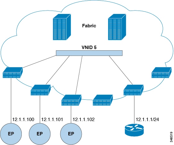
The ACI fabric is unaware of the presence of the external router and the APIC statically assigns the leaf switch interface to its EPG.
The documentation set for this product strives to use bias-free language. For the purposes of this documentation set, bias-free is defined as language that does not imply discrimination based on age, disability, gender, racial identity, ethnic identity, sexual orientation, socioeconomic status, and intersectionality. Exceptions may be present in the documentation due to language that is hardcoded in the user interfaces of the product software, language used based on RFP documentation, or language that is used by a referenced third-party product. Learn more about how Cisco is using Inclusive Language.
This chapter contains the following sections:
The ACI fabric is unaware of the presence of the external router and the APIC statically assigns the leaf switch interface to its EPG.
A bridge domain (fvBD) represents a Layer 2 forwarding construct within the fabric. The following figure shows the location of bridge domains in
the management information tree (MIT) and their relation to other objects in the tenant.

A bridge domain must be linked to a VRF instance (also known as a context or private network). With the exception of a Layer
2 VLAN, it must have at least one subnet (fvSubnet) associated with it. The bridge domain defines the unique Layer 2 MAC address space and a Layer 2 flood domain if such flooding
is enabled. While a VRF instance defines a unique IP address space, that address space can consist of multiple subnets. Those
subnets are defined in one or more bridge domains that reference the corresponding VRF instance.
The options for a subnet under a bridge domain or under an EPG are as follows:
Public: The subnet can be exported to a routed connection.
Private: The subnet applies only within its tenant.
Shared: The subnet can be shared with and exported to multiple VRF instances in the same tenant or across tenants as part of a shared service. An example of a shared service is a routed connection to an EPG present in another VRF instance in a different tenant. This enables traffic to pass in both directions across VRF instances. An EPG that provides a shared service must have its subnet configured under that EPG (not under a bridge domain), and its scope must be set to advertised externally, and shared between VRF instances.
 Note |
Shared subnets must be unique across the VRF instance involved in the communication. When a subnet under an EPG provides a Layer 3 external network shared service, such a subnet must be globally unique within the entire Cisco Application Centric Infrastructure (ACI) fabric. |
Bridge domain packet behavior can be controlled in the following ways:
|
Packet Type |
Mode |
||
|---|---|---|---|
|
ARP |
You can enable or disable ARP Flooding; without flooding, ARP packets are sent with unicast.
|
||
|
Unknown Unicast |
L2 Unknown Unicast, which can be Flood or Hardware Proxy.
Modifying the L2 Unknown Unicast setting causes traffic to bounce (go down and up) on interfaces to devices attached to EPGs associated with this bridge domain. |
||
|
Unknown IP Multicast |
L3 Unknown Multicast Flooding Flood: Packets are flooded on ingress and border leaf switch nodes only. With N9K-93180YC-EX, packets are flooded on all the nodes where a bridge domain is deployed. Optimized: Only 50 bridge domains per leaf are supported. This limitation is not applicable for N9K-93180YC-EX. |
||
|
L2 Multicast, Broadcast, Unicast |
Multi-Destination Flooding, which can be one of the following:
|
Note |
Beginning with Cisco APIC release 3.1(1), on the Cisco Nexus 9000 series switches (with names ending with EX and FX and onwards), the following protocols can be flooded in encapsulation or flooded in a bridge domain: OSPF/OSPFv3, BGP, EIGRP, LACP, ISIS, IGMP, PIM, ST-BPDU, ARP/GARP, RARP, and ND. |
Bridge domains can span multiple switches. A bridge domain can contain multiple subnets, but a subnet is contained within
a single bridge domain. If the bridge domain (fvBD) limitIPLearnToSubnets property is set to yes, endpoint learning will occur in the bridge domain only if the IP address is within any of the configured subnets for the
bridge domain or within an EPG subnet when the EPG is a shared service provider. Subnets can span multiple EPGs; one or more
EPGs can be associated with one bridge domain or subnet. In hardware proxy mode, ARP traffic is forwarded to an endpoint in
a different bridge domain when that endpoint has been learned as part of the Layer 3 lookup operation.
A bridge domain can be set to operate in flood mode for unknown unicast frames or in an optimized mode that eliminates flooding for these frames. When operating in flood mode, Layer 2 unknown unicast traffic is flooded over the multicast tree of the bridge domain (GIPo). For the bridge domain to operate in optimized mode you should set it to hardware-proxy. In this case, Layer 2 unknown unicast frames are sent to the spine-proxy anycast VTEP address.
 Caution |
Changing from unknown unicast flooding mode to hw-proxy mode is disruptive to the traffic in the bridge domain. |
If IP routing is enabled in the bridge domain, the mapping database learns the IP address of the endpoints in addition to the MAC address.
The Layer 3 Configurations tab of the bridge domain panel allows the administrator to configure the following parameters:
Unicast Routing: If this setting is enabled and a subnet address is configured, the fabric provides the default gateway function and routes the traffic. Enabling unicast routing also instructs the mapping database to learn the endpoint IP-to-VTEP mapping for this bridge domain. The IP learning is not dependent upon having a subnet configured under the bridge domain.
Subnet Address: This option configures the SVI IP addresses (default gateway) for the bridge domain.
Limit IP Learning to Subnet: This option is similar to a unicast reverse-forwarding-path check. If this option is selected, the fabric will not learn IP addresses from a subnet other than the one configured on the bridge domain.
Caution |
Enabling Limit IP Learning to Subnet is disruptive to the traffic in the bridge domain. |
In Cisco Application Centric
Infrastructure (ACI), the same VLAN ID can be reused for any purpose as long as the VLAN is deployed on different leaf nodes. This allows the
Cisco ACI fabric to overcome the theoretical maximum number of VLANs 4094 as a fabric. However, to accomplish this, and also to hide
the complexity of underlying VxLAN implementation, each individual leaf node can contain smaller number of VLANs. This may
pose a problem when the density of VLANs per leaf node is required. In such a scenario, you can enable Scaled L2 Only mode, formerly known as legacy mode on the bridge domain. A bridge domain in scaled L2 only mode allows large number of VLANs
per leaf node. However, such a bridge domain has some limitations.
For the number of VLANs or bridge domains supported per leaf node with or without scaled L2 only mode, see Verified Scalability Guide for your specific release.
The following are limitations for legacy mode or scaled L2 only mode.
The bridge domain can contain only one EPG and one VLAN.
Unicast routing is not supported.
Contracts are not supported.
Dynamic VLAN allocation for VMM integration is not supported.
Service graph is not supported.
A QoS policy is not supported.
The bridge domain essentially behaves as a VLAN in standalone Cisco NX-OS.
The following are considerations to configure a bridge domain in scaled L2 only mode.
VLAN ID is configured on the bridge domain.
VLAN IDs configured under the EPG are overridden.
Enabling or disabling a scaled L2 only mode on an existing bridge domain will impact service.
Cisco Application Policy Infrastructure Controller (APIC) will automatically undeploy and redeploy the bridge domain when the VLAN ID is different from what was used prior to the change.
When the same VLAN ID is used before and after the mode change, Cisco APIC will not automatically undeploy and redeploy the bridge domain. You must manually undeploy and redeply the bridge domain, which can be performed by deleting and recreating the static port configuration under the EPG.
When changing the VLAN ID for scaled L2 only mode, you must first disable the mode, then enable scaled L2 only mode with the new VLAN ID.
You can disable IP dataplane learning for a bridge domain. The MAC learning still occurs in the hardware, but the IP learning only occurs from the ARP/GARP/ND processes. This functionality was introduced in the Cisco APIC 3.1 releases primarily for service graph policy-based redirect (PBR) deployments, and it has been superseded by the ability to disable IP dataplane learning per-VRF instance (Cisco APIC release 4.0), per bridge domain subnet (Cisco APIC release 5.2), and per-EPG (Cisco APIC release 5.2). We do not recommend disabling IP learning per bridge domain and it is not supported except when used with PBR.
See the following guidelines and limitations for disabling IP learning per bridge domain:
Layer 3 multicast is not supported because the source IP address is not learned to populate the S,G information in the remote leaf switches.
As the DL bit is set in the iVXLAN header, the MAC address is also not learned from the data path in the remote leaf switches. It results in flooding of the unknown unicast traffic from the remote leaf switch to all leaf switches in the fabric where this bridge domain is deployed. We recommend that you configure the bridge domain in proxy mode to overcome this situation if endpoint dataplane learning is disabled.
ARP should be in flood mode and GARP based detection should be enabled.
When IP learning is disabled, Layer 3 endpoints are not flushed in the corresponding VRF instance. It may lead to the endpoints pointing to the same leaf switch forever. To resolve this issue, flush all the remote IP endpoints in this VRF on all leaf switches.
The configuration change of disabling dataplane learning on the bridge domain does not flush previously locally learned endpoints. This limits the disruption to existing traffic flows. MAC learned endpoints age as usual if the Cisco ACI leaf switch sees no traffic with the given source MAC for longer than the endpoint retention policy.
Note |
Disabling IP dataplane learning means that the endpoint IP information is not updated as a result of traffic forwarding, but
Cisco ACI can refresh the endpoint IP information with ARP/ND. This means that the aging of the local endpoints (whether they were
learned before the configuration change, or they are learned after the configuration change) differs slightly from the normal
aging and it depends also from If If |
If you have a public subnet when you configure the routed outside, you must associate the bridge domain with the outside configuration.
|
Step 1 |
On the menu bar, choose . |
|
Step 2 |
In the Create Tenant dialog box, perform the following tasks: |
|
Step 3 |
In the Work pane, drag the VRF icon to the canvas to open the Create VRF dialog box, and perform the following tasks:
|
|
Step 4 |
In the Work pane, drag the Brdige Domain icon to the canvas within the circle around the VRF instance to connect the two. In the Create Bridge Domain dialog box that displays, perform the following tasks:
|
|
Step 5 |
In the Work pane, drag the L3 icon to the canvas within the circle around the VRF instance to connect the two. In the Create Routed Outside dialog box that displays, perform the following tasks:
|
Note |
Before creating the tenant configuration, you must create a VLAN domain using the vlan-domain command and assign the ports to it. |
|
Step 1 |
Create a VLAN domain (which contains a set of VLANs that are allowable in a set of ports) and allocate VLAN inputs, as follows: Example:In the following example ("exampleCorp"), note that VLANs 50 - 500 are allocated. |
||
|
Step 2 |
Once the VLANs have been allocated, specify the leaf (switch) and interface for which these VLANs can be used. Then, enter "vlan-domain member" and then the name of the domain you just created. Example:In the following example, these VLANs (50 - 500) have been enabled on leaf 101 on interface ethernet 1/2-4 (three ports including 1/2, 1/3, and 1/4). This means that if you are using this interface, you can use VLANS 50-500 on this port for any application that the VLAN can be used for. |
||
|
Step 3 |
Create a tenant in global configuration mode, as shown in the following example: Example: |
||
|
Step 4 |
Create a private network (also called VRF) in tenant configuration mode as shown in the following example: Example: |
||
|
Step 5 |
Create a bridge domain (BD) under the tenant, as shown in the following example: Example:
|
||
|
Step 6 |
Allocate IP addresses for the BD (ip and ipv6), as shown in the following example. Example: |
The next section describes how to add an application profile, create an application endpoint group (EPG), and associate the EPG to the bridge domain.
An enforced bridge domain configuration entails creating an endpoint in a subject endpoint group (EPG) that can only ping subnet gateways within the associated bridge domain. With this configuration, you can then create a global exception list of IP addresses that can ping any subnet gateway.

Note |
|
|
Step 1 |
Create and enable the tenant: Example:In the following example ("cokeVrf") is created and enabled. |
|
Step 2 |
Add the subnet to the exception list. Example: |
apic1# show running-config all | grep bd-enfbd-enforce enablebd-enf-exp-ip add 1.2.3.4/24apic1(config)# no bd-enf-exp-ip 1.2.3.4/24apic1(config)#tenant cokeapic1(config-tenant)#vrf context cokeVrfapic1(config-tenant-vrf)# no bd-enforce enableCisco Application Centric Infrastructure (ACI) uses the bridge domain as the Layer 2 broadcast boundary. Each bridge domain can include multiple endpoint groups (EPGs), and each EPG can be mapped to multiple virtual or physical domains. Each EPG can also use different VLAN encapsulation pools in each domain. Each EPG can also use different VLAN or VXLAN encapsulation pools in each domain.
Ordinarily, when you put multiple EPGs within bridge domains, broadcast flooding sends traffic to all the EPGs in the bridge domain. Because EPGs are used to group endpoints and manage traffic to fulfill specific functions, sending the same traffic to all the EPGs in the bridge domain is not always practical.
The flood in encapsulation feature helps to consolidate bridge domains in your network. The feature does so by enabling you to control broadcast flooding to endpoints within the bridge domain based on the encapsulation of the virtual or physical domain that the EPGs are associated with.
Flood in encapsulation requires the bridge domain to be configured with a subnet and with IP routing because in order to allow communication between endpoints of different EPGs in the same bridge domain Cisco ACI performs proxy ARP.
Flood in encapsulation is often used when the external device is using Virtual Connect Tunnel mode where one MAC address is maintained per vNet because of VLAN-agnostic MAC learning.
Using multiple VLANs in tunnel mode can introduce a few challenges. In a typical deployment using Cisco ACI with a single tunnel, as illustrated in the following figure, there are multiple EPGs under one bridge domain. In this case, certain traffic is flooded within the bridge domain (and thus in all the EPGs), with the risk of MAC learning ambiguities that can cause forwarding errors.

In this topology, the blade switch (virtual connect in this example) has a single tunnel network defined that uses one uplink to connect with the Cisco ACI leaf node. Two user VLANs, VLAN 10 and VLAN 11 are carried over this link. The bridge domain is set in flooding mode as the servers’ gateways are outside the Cisco ACI cloud. ARP negotiations occur in the following process:
The server sends one ARP broadcast request over the VLAN 10 network.
The ARP packet travels through the tunnel network to the external server, which records the source MAC address, learned from its downlink.
The server then forwards the packet out its uplink to the Cisco ACI leaf switch.
The Cisco ACI fabric sees the ARP broadcast packet entering on access port VLAN 10 and maps it to EPG1.
Because the bridge domain is set to flood ARP packets, the packet is flooded within the bridge domain and thus to the ports under both EPGs as they are in the same bridge domain.
The same ARP broadcast packet comes back over the same uplink.
The blade switch sees the original source MAC address from this uplink.
Result: The blade switch has the same MAC address learned from both the downlink port and uplink port within its single MAC forwarding table, causing traffic disruptions.
The flood in encapsulation option is used to limit flooding traffic inside the bridge domain to a single encapsulation. When EPG1/VLAN X and EPG2/VLAN Y share the same bridge domain and flood in encapsulation is enabled, the encapsulation flooding traffic does not reach the other EPG/VLAN.
Beginning with Cisco Application Policy Infrastructure Controller (APIC) release 3.1(1), on the Cisco Nexus 9000 series switches (with names ending with EX and FX and onwards), all protocols are flooded in encapsulation. Also, when flood in encapsulation is enabled under the bridge domain for any inter-VLAN traffic, Proxy ARP ensures that the MAC flap issue does not occur. It also limits all flooding (ARP, GARP, and BUM) to the encapsulation. The restriction applies for all EPGs under the bridge domain where it is enabled.
Note |
Before Cisco APIC release 3.1(1), these features are not supported (proxy ARP and all protocols being included when flooding within encapsulation). In an earlier Cisco APIC release or earlier generation switches (without EX or FX on their names), if you enable flood in encapsulation it does not function, no informational fault is generated, but Cisco APIC decreases the health score by 1. |
Note |
Beginning with Cisco APIC release 3.2(5), you can configure flood in encapsulation for EPGs associated with VXLAN encapsulation. Previously, only VLANs were supported for flood in encapsulation for virtual domains. You configure flood in encapsulation when you create or modify a bridge domain or an EPG. |
The recommended solution is to support multiple EPGs under one bridge domain by adding an external switch. This design with multiple EPGs under one bridge domain with an external switch is illustrated in the following figure.

Within the same bridge domain, some EPGs can be service nodes and other EPGs can have flood in encapsulation configured. A load balancer resides on a different EPG. The load balancer receives packets from the EPGs and sends them to the other EPGs (There is no Proxy ARP and flood within encapsulation does not take place).
The EPG/bridge domain level broadcast segmentation is supported for the following network control protocols:
OSPF
EIGRP
LACP
IS-IS
BGP
IGMP
PIM
STP-BPDU (flooded within EPG)
ARP/GARP (controlled by ARP Proxy)
ND
The following limitations apply when using flood in encapsulation for all protocols:
Flood in encapsulation does not work in ARP unicast mode.
Neighbor Solicitation (Proxy NS/ND) is not supported for this release.
Because proxy Address Resolution Protocol (ARP) is enabled implicitly, ARP traffic can go to the CPU for communication between different encapsulations.
To ensure even distribution to different ports to process ARP traffic, enable per-port Control Plane Policing (CoPP) for ARP with flood in encapsulation.
Flood in encapsulation is supported only in bridge domain in flood mode and ARP in flood mode. Bridge domain spine proxy mode is not supported.
IPv4 Layer 3 multicast is not supported.
IPv6 NS/ND proxy is not supported when flood in encapsulation is enabled. As a result, the connection between two endpoints that are under same IPv6 subnet but resident in EPGs with different encapsulation may not work.
Virtual machine migration to a different VLAN has momentary issues (60 seconds). Virtual machine migration to a different VLAN or VXLAN has momentary issues (60 seconds).
Setting up communication between virtual machines through a firewall, as a gateway, is not recommended because if the virtual machine IP address changes to the gateway IP address instead of the firewall IP address, then the firewall can be bypassed.
Prior releases are not supported (even interoperating between prior and current releases).
A mixed-mode topology with older-generation Application Leaf Engine (ALE) and Application Spine Engine (ASE) is not recommended and is not supported with flood in encapsulation. Enabling them together can prevent QoS priorities from being enforced.
Flood in encapsulation is not supported for EPG and bridge domains that are extended across Cisco ACI fabrics that are part of the same Multi-Site domain. However, flood in encapsulation is still working and fully supported, and works for EPGs or bridge domains that are locally defined in Cisco ACI fabrics, independently from the fact those fabrics may be configured for Multi-Site. The same considerations apply for EPGs or bridge domains that are stretched between Cisco ACI fabric and remote leaf switches that are associated to that fabric.
Flood in encapsulation is not supported on EPGs where microsegmentation is configured.
Flood in encapsulation is not supported for Common Pervasive Gateway. See the chapter "Common Pervasive Gateway" in the Cisco APIC Layer 3 Networking Configuration Guide.
If you configure the flood in encapsulation on all EPGs of a bridge domain, ensure that you configure the flood in encapsulation on the bridge domain as well.
IGMP snooping is not supported with flood in encapsulation.
There is a condition that causes Cisco ACI to flood in the bridge domain (instead of the encapsulation) packets that are received on an EPG that is configured for flood in encapsulation. This happens regardless of whether the administrator configured flood in encapsulation directly on the EPG or on the bridge domain. The condition for this forwarding behavior is if the ingress leaf node has a remote endpoint for the destination MAC address while the egress leaf node does not have a corresponding local endpoint. This can happen due to reasons such as an interface flapping, an endpoint flush due to STP TCN, learning being disabled on the bridge domain due to an excessive amount of moves, and so on.
In the 4.2(6o) and later 4.2(6) releases, 4.2(7m) and later 4.2(7) releases, and 5.2(1g) and later releases, this behavior was enhanced. If the administrator enables flood in encapsulation on the bridge domain (instead of the EPG), Cisco ACI does not send out such packets on any encapsulations from downlinks facing external devices on the non-ingress (egress and transit) leaf nodes. This new behavior prevents the packets from leaking to unexpected encapsulations. When flood in encapsulation is enabled only at an EPG level, the non-ingress leaf node may still flood packets in the bridge domain instead of the encapsulation. For more information, see the enhancement bug CSCvx83364.
A Layer 3 gateway must be in the Cisco ACI fabric.
You configure flood in encapsulation with the NX-OS style CLI, REST API, or the Cisco Application Policy Infrastructure Controller (APIC) GUI.
Flood in encapsulation that is configured for an EPG takes precedence over flood in encapsulation that is configured for a bridge domain (BD). When both BDs and EPGs are configured, the behavior is described as follows:
|
Configuration |
Behavior |
|---|---|
|
Flood in encapsulation at the EPG and flood in encapsulation at the bridge domain |
Flood in encapsulation takes place for the traffic on all VLANs and VXLANs the bridge domain. |
|
No flood in encapsulation at the EPG and flood in encapsulation at the bridge domain |
Flood in encapsulation takes place for the traffic on all VLANs and VXLANs within the bridge domain. |
|
Flood in encapsulation at the EPG and no flood in encapsulation at the bridge domain |
Flood in encapsulation takes place for the traffic on that VLAN or VXLAN within the EPG of the bridge domain. |
|
No flood in encapsulation at the EPG and no flood in encapsulation at the bridge domain |
Flooding takes place within the entire bridge domain. |
You configure flood in encapsulation using the Cisco Application Policy Infrastructure Controller (APIC) GUI when you create or modify a bridge domain (BD) or an endpoint group (EPG).
|
Step 1 |
To configure flood in encapsulation while creating a BD, complete the following steps:
|
|
Step 2 |
To configure flood in encapsulation while modifying a BD, complete the following steps:
|
|
Step 3 |
To configure flood in encapsulation while creating an EPG, complete the following steps: |
|
Step 4 |
To configure flood in encapsulation while modifying an EPG, complete the following steps:
|
If you want to add flood in encapsulation only for selective endpoint groups (EPGs) using the NX-OS style CLI, enter the flood-on-encapsulation enable command under EPGs.
If you want to add flood in encapsulation for all EPGs, you can use themulti-destination encap-flood CLI command for the bridge domain.
|
Step 1 |
Configure flood in encapsulation for the bridge domain (BD). Example: |
|
Step 2 |
Configure flood in encapsulation for the EPG. Example: |
 Feedback