Cisco ACI with Microsoft Windows Azure Pack

This chapter contains the following sections:

About Cisco ACI with Microsoft Windows Azure Pack

Cisco Application Centric Infrastructure (ACI) integrates in Microsoft Windows Azure Pack to provide a self-service experience for the tenant.

ACI enhances the network management capabilities of the platform. Microsoft Windows Azure Pack is built on top of an existing Microsoft System Center Virtual Machine Manager (SCVMM) installation. Cisco ACI has integration points at each of these layers, enabling you to leverage the work performed in a SCVMM environment and use it in a Microsoft Windows Azure Pack installation.

  • Cisco ACI with Microsoft Windows Azure Pack—Microsoft Windows Azure Pack for Windows Server is a collection of Microsoft Azure technologies that include the following capabilities:

    • Management portal for tenants

    • Management portal for administrators

    • Service management API

  • Cisco ACI with Microsoft System Center Virtual Machine Manager —For information about how to set up Cisco ACI with Microsoft System Center Virtual Machine Manager (SCVMM), see details in Cisco ACI with Microsoft SCVMM Solution Overview.


Note


You cannot configure direct server return (DSR) through Windows Azure Pack. If you want to configure DSR, you must do so in Cisco APIC. See the chapter "Configuring Direct Server Return" in the Cisco APIC Layer 4 to Layer 7 Services Deployment Guide for information.

Cisco ACI with Microsoft Windows Azure Pack Solution Overview

Cisco Application Centric Infrastructure (ACI) integrates in Microsoft Windows Azure Pack to provide a self-service experience for tenants. ACI resource provider in Windows Azure Pack drives the Application Policy Infrastructure Controller (APIC) for network management. Networks are created in System Center Virtual Machine Manager (SCVMM) and are available in Windows Azure Pack for respective tenants. ACI Layer 4 to Layer 7 capabilities for F5 and Citrix load balancers and stateless firewall are provided for tenants. For details, see the About Load Balancing.

Windows Azure Pack for Windows Server is a collection of Microsoft Azure technologies, available to Microsoft customers at no additional cost for installation into your data center. It runs on top of Windows Server 2012 R2 and System Center 2012 R2 and, through the use of the Windows Azure technologies, enables you to offer a rich, self-service, multi-tenant cloud, consistent with the public Windows Azure experience.

Windows Azure Pack includes the following capabilities:

  • Management portal for tenants—a customizable self-service portal for provisioning, monitoring, and managing services such as networks, bridge domains, VMs, firewalls, load balancers, external connectivity, and shared services. See the User Portal GUI.

  • Management portal for administrators—a portal for administrators to configure and manage resource clouds, user accounts, and tenant offers, quotas, pricing, Web Site Clouds, Virtual Machine Clouds, and Service Bus Clouds.

  • Service management API—a REST API that helps enable a range of integration scenarios including custom portal and billing systems.

See Use Case Scenarios for the Administrator and Tenant Experience for details.

Physical and Logical Topology

Figure 1. Topology of a typical Windows Azure Pack deployment with ACI Fabric


The above figure shows a representative topology of a typical Windows Azure Pack deployment with Cisco Application Centric Infrastructure (ACI) fabric. Connectivity between Windows Azure Pack and Application Policy Infrastructure Controller (APIC) is over the management network. Tenants interface is only with Windows Azure Pack either through the GUI or REST API. Tenants do not have direct access to APIC.

Figure 2. ACI in Resource Provider Framework


About the Mapping of ACI Constructs in Microsoft Windows Azure Pack

This section shows a table of the mapping of Cisco Application Centric Infrastructure (ACI) constructs in Microsoft Windows Azure Pack.

Table 1. Mapping of ACI and Windows Azure Pack constructs

Windows Azure Pack

ACI

Subscription

Tenant

Network

EPG

Firewall Rule

Intra-tenant contract

Shared Service

Inter-tenant contract

SCVMM Cloud

VM Domain

Getting Started with Cisco ACI with Microsoft Windows Azure Pack

This section describes how to get started with Cisco ACI with Microsoft Windows Azure Pack.

Before you install Cisco ACI with Microsoft Windows Azure Pack, download and unzip the folder containing the Cisco ACI and matching Microsoft integration files for the Cisco APIC release.

  1. Go to Cisco's Application Policy Infrastructure Controller (APIC) website.

  2. Choose All Downloads for this Product > APIC Software.

  3. Choose the release version and the matching zipped folder.

  4. Click Download.

  5. Unzip the zipped folder.


Note


Cisco ACI with Microsoft Windows Azure Pack only supports ASCII characters. Non-ASCII characters are not supported.

Ensure that English is set in the System Locale settings for Windows, otherwise Cisco ACI with Windows Azure Pack will not install. Also, if the System Locale is modified to a non-English Locale after installation, the integration components may fail when communicating with Cisco APIC and the Cisco ACI fabric.


Prerequisites for Getting Started with Cisco ACI with Microsoft Windows Azure Pack

Before you get started, ensure that you have verified that your computing environment meets the following prerequisites:

  • Ensure Cisco Application Centric Infrastructure (ACI) with Microsoft System Center Virtual Machine Manager (SCVMM) has been set up.

    For more information, see Getting Started with Cisco ACI with Microsoft SCVMM.

  • Ensure that Microsoft Windows Azure Pack Update Rollup 5, 6, 7, 9, 10, or 11 is installed.

    See Microsoft's documentation.

  • Ensure that Windows Server 2016 is installed.

    See Microsoft's documentation.

  • Ensure that Hyper-V Host is installed.

    See Microsoft's documentation.

  • Ensure a cloud is configured on SCVMM.

    See Microsoft's documentation.

  • Ensure a VM cloud is configured on Windows Azure Pack.

    See Microsoft's documentation.

  • Ensure "default" AEP exists with infrastructure VLAN enabled.

  • Ensure "default" and "vpcDefault" bridge domains and corresponding "default" and "vpcDefault" EPGs exist in tenant common.

  • Ensure you have the Cisco MSI files for APIC Windows Azure Pack Resource and the Host Agent.

    For more information, see Getting Started with Cisco ACI with Microsoft SCVMM.


Note


Symptom: When you either create or update a plan it may fail with an error message.

Condition: If you have configured Microsoft's Windows Azure Pack without the FQDN, you will encounter the following error message:

Cannot validate the new quota settings because one of the underlying services failed to respond. Details: An error has occurred.

Workaround: When you configure the VM Clouds, follow Microsoft's Windows Azure Pack UI instructions which informs you to use the FQDN for your SCVMM server.


Installing, Setting Up, and Verifying the Cisco ACI with Microsoft Windows Azure Pack Components

This section describes how to install, set up, and verify the Cisco ACI with Microsoft Windows Azure Pack components.

Component

Task

Install ACI Azure Pack Resource Provider

See Installing ACI Azure Pack Resource Provider.

Install the OpflexAgent certificate

See Installing the OpflexAgent Certificate.

Configure ACI Azure Pack Resource Provider Site

See Configuring ACI Azure Pack Resource Provider Site.

Install ACI Azure Pack Admin site extension

See Installing ACI Azure Pack Admin Site Extension.

Install ACI Azure Pack tenant site extension

See Installing ACI Azure Pack Tenant Site Extension.

Set up the ACI

See Setting Up ACI.

Verify the Windows Azure Pack Resource Provider

See Verifying the Windows Azure Pack Resource Provider.

Installing ACI Azure Pack Resource Provider

This section describes how to install ACI Azure Pack Resource Provider on the Windows Azure Pack server.

Procedure

Step 1

Log in to the Microsoft Service Provider Foundation Server which provides VM Clouds in the Windows Azure Pack environment. Locate and copy over ACI Azure Pack - Resource Provider Site.msi file.

Step 2

Double-click the ACI Azure Pack - Resource Provider Site.msi file.

Step 3

In the Setup dialog box, perform the following actions to install ACI Azure Pack - Resource Provider:

  1. Check the I accept the terms in the License Agreement check box.

  2. Click Install.

  3. Click Install.

  4. Click Finish.


Installing the OpflexAgent Certificate

This section describes how to install the OpflexAgent Certificate.

Procedure

Step 1

Log in to the Windows Azure Pack server with administrator credentials.

Step 2

Use one of the following methods:

  • For large-scale deployments, see Microsoft's documentation for Deploy Certificates by Using Group Policy:

    https://technet.microsoft.com/en-us/library/cc770315(v=ws.10).aspx.

  • For small-scale deployments follow these steps:

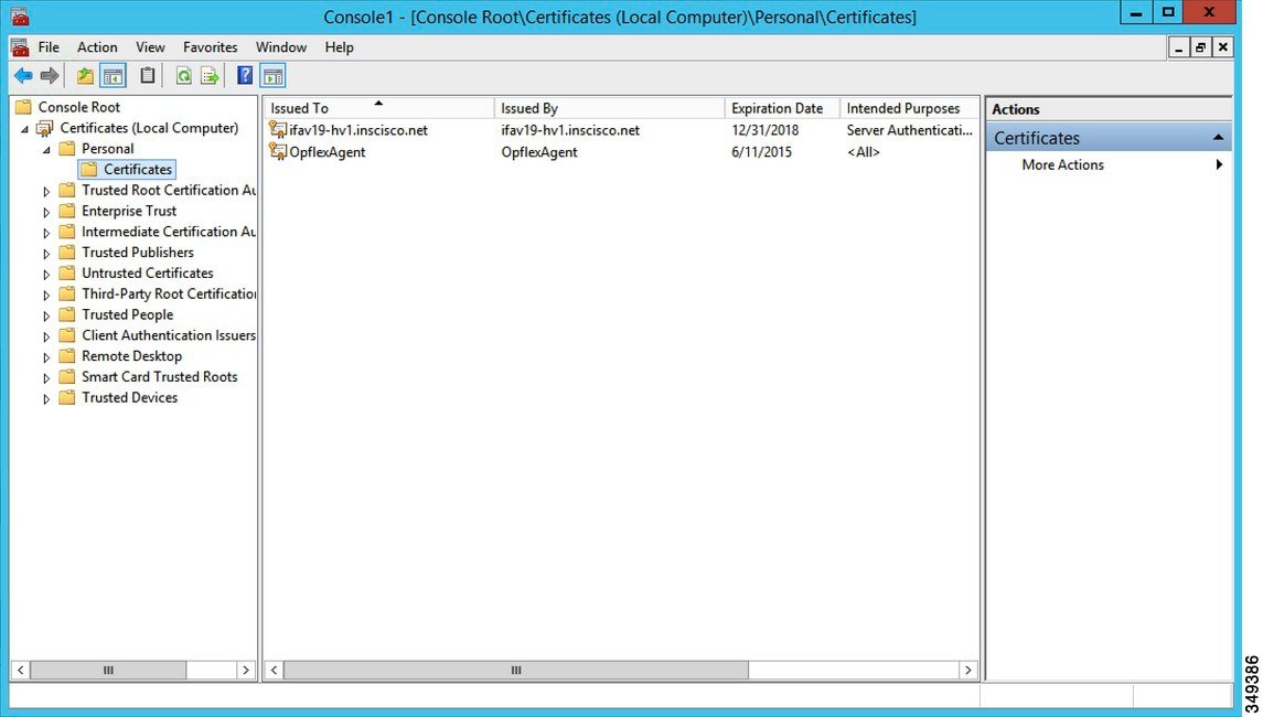
    You must add OpFlex security certificate to the local system. The ACI Windows Azure Pack resource provider uses the same security certificate file from the Cisco ACI SCVMM installation process located on your SCVMM Server at: C:\Program Files (x86)\ApicVMMService\OpflexAgent.pfx. Copy this file to the Windows Azure Pack Resource Provider Server. If the following steps are not performed on your ACI Windows Azure Pack resource provider servers, the APIC ACI Windows Azure Pack resource provider cannot communicate with the Application Policy Infrastructure Controller (APIC) .

    Install the OpFlex security certificate on the ACI Windows Azure Pack resource provider Windows Server 2012 local machine’s certificate repository. On each ACI Windows Azure Pack resource provider server, install this certificate by performing the following steps:

    1. Choose Start > Run.

    2. Enter mmc and click OK.

    3. In the Console Root window, on the menu bar, choose Add/Remove Snap-in.

    4. In the Available Snap-ins field, choose Certificates and click Add.

    5. In the Certificates snap-in dialog box, choose the Computer Account radio button, and click Next.

    6. In the Select Computer dialog box, choose the Local Computer radio button, and click Finish.

    7. Click OK to go back to the main MMC Console window.

    8. In the MMC Console window, double-click Certificates (local computer) to expand its view.

    9. Right-click Certificates under Personal and choose All Tasks > Import.

    10. In the Certificates Import Wizard dialog box, perform the following actions:

      1. Click Next.

      2. Browse to the Opflex Agent file and click Next.

    11. Enter the password for the certificate that was provided when you installed MSI.

    12. You must choose the Mark this key as exportable. This will allow you to back up or transport your keys at a later time radio button.

    13. Choose the Include all extended properties radio button.

    14. Choose the Place all certificates in the following store radio button, browse to locate Personal, and click Next.

    15. Click Finish.

    16. Click OK.


Configuring ACI Azure Pack Resource Provider Site

This section describes how to configure ACI Azure Pack Resource Provider IIS Site on the Windows Azure Pack server.

Procedure

Step 1

Log in to the Windows Azure Pack server and open the Internet Information Services Manager Application.

Step 2

Navigate to Application Pools > Cisco-ACI.

Step 3

Click the Advanced Settings in the Actions tab.

  1. Locate the Identity field and click on the ellipses to the left of the scroll bar.

  2. Select Custom Account and input your account name and password credentials for Service Provider Foundation Administrator. The Service Provider Foundation Administrator user account should have the following group memberships: Administrators, SPF_Admin. This user account is required as the Resource Provider queries the attached SCVMM servers. In addition, the User Credentials must have permission to write to the Local Machine Registry and have Read/Write access to the following directory for Resource Provider Logging:

    C:\Windows\System32\config\systemprofile\AppData\Local

  3. Click OK to exit Application Pool Identity.

Step 4

Click OK to exit Advanced Settings


Installing ACI Azure Pack Admin Site Extension

This section describes how to install ACI Azure Pack Admin Site Extension on the Windows Azure Pack server.

Procedure

Step 1

Log in to the Windows Azure Pack server and locate the ACI Azure Pack - Admin Site Extension.msi file.

Step 2

Double-click the ACI Azure Pack - Admin Site Extension.msi file.

Step 3

In the Setup dialog box, perform the following actions to install ACI Azure Pack - Admin Site Extension:

  1. Check the I accept the terms in the License Agreement check box.

  2. Click Install.

  3. Click Finish.


Installing ACI Azure Pack Tenant Site Extension

This section describes how to install ACI Azure Pack Tenant Site Extension on the Windows Azure Pack server.

Procedure

Step 1

Log in to the Windows Azure Pack server and locate the ACI Azure Pack - Tenant Site Extension.msi file.

Step 2

Double-click the ACI Azure Pack - Tenant Site Extension.msi file.

Step 3

In the Setup dialog box, perform the following actions to install ACI Azure Pack - Tenant Site Extension:

  1. Check the I accept the terms in the License Agreement check box.

  2. Click Install.

  3. Click Finish.


Setting Up ACI

This section describes how to setup ACI.

Procedure

Step 1

Log in to the Service Management Portal.

Step 2

In the navigation pane, choose ACI.

If you do not see ACI, click Refresh.

Step 3

Click the QuickStart icon.

Step 4

In the QuickStart pane, perform the following actions in order:

  1. Click on Register your ACI REST endpoint.

  2. In the ENDPOINT URL field, enter the resource provider address:Cisco-ACI port (http://resource_provider_address:50030).

  3. In the USERSNAME field, enter the user name (domain administrator).

  4. In the PASSWORD field, enter the password (domain administrator password).

Step 5

Choose the ACI > Setup tab, and perform the following actions:

  1. In the APIC ADDRESS field, enter the APIC IP Address(es).

  2. In the CERTIFICATE NAME field, enter OpflexAgent.


Verifying the Windows Azure Pack Resource Provider

This section describes how to verify the Windows Azure Pack Resource Provider.

Procedure

Step 1

Log in to the Service Management Portal (Admin Portal).

Step 2

In the navigation pane, choose ACI.

Step 3

In the aci pane, choose the QuickStart Cloud icon.

Ensure the Register your ACI REST Endpoint link is greyed out.

Step 4

In the aci pane, choose SETUP.

Ensure that you see the APIC Address has valid apic addresses and the Certificate name is OpflexAgent.


Upgrading the Cisco ACI with Microsoft Windows Azure Pack Components

Prerequisites:

Microsoft servers that you integrate into ACI must be updated with the KB2919355 and KB3000850 update rollups prior to upgrading ACI to the 2.0(1) release. The KB2919355 update rollup includes the 2929781 patch, which adds new TLS cipher suites and changes the cipher suite priorities in Windows 8.1 and Windows Server 2012 R2.

You must patch the following Microsoft servers:

  • Microsoft Windows Azure Pack Resource Provider Servers

  • Microsoft Windows Azure Pack Tenant Site Servers

  • Microsoft Windows Azure Pack Admin Site Servers

  • Microsoft System Center Service Provider Foundation/Orchestration Servers

  • Microsoft System Center 2012 R2 Servers

  • Microsoft HyperV 2012 R2 Servers

To upgrade the .msi files for each Cisco ACI with Windows Azure Pack Integration follow the Microsoft general guidelines for upgrading Windows Azure Pack Components listed per Update Rollup. The general guidelines are:

  • If the system is currently operational (handling customer traffic), schedule downtime for the Azure servers. The Windows Azure Pack does currently not support rolling upgrades.

  • Stop or redirect customer traffic to sites that you consider satisfactory.

  • Create backups of the computers.


Note


If you are using virtual machines (VMs), take snapshots of their current state.

If you are not using VMs, take a backup of each MgmtSvc-* folder in the inetpub directory on each machine that has a Windows Azure Pack component installed.

Collect information and files that are related to your certificates, host headers, or any port changes.

Once the upgrade is complete and has been verified, follow Hyper-V best practices regarding managing VM snapshots: https://technet.microsoft.com/en-us/library/dd560637(v=ws.10).aspx


Upgrading the ACI Windows Azure Pack Workflow

This section describes upgrading the ACI Windows Azure Pack Workflow.

Procedure


Step 1

Upgrade the APIC Controller and the Switch Software.

See the Cisco APIC Firmware Management Guide.

Step 2

Upgrade the ACI Windows Azure Pack.

If upgrading from a prior release of 1.1(2x):

  1. You must uninstall the APIC Windows Azure Pack Resource Provider, see Uninstalling the APIC Windows Azure Pack Resource Provider.

  2. Follow the steps that are outlined in the Installing, Setting Up, and Verifying the Cisco ACI with Microsoft Windows Azure Pack Components.

  3. Skip to step 6, Upgrade the APIC SCVMM Agent on SCVMM or Upgrade the APIC SCVMM Agent on a Highly Available SCVMM.

If upgrading from release 1.1(2x) or later:

  1. Proceed to step 3.

Step 3

Upgrade the ACI Windows Azure Pack Resource Provider.

For more information, see Upgrading the ACI Windows Azure Pack Resource Provider.

Step 4

Upgrade the ACI Azure Pack Admin Site Extension.

For more information, see Upgrading the ACI Azure Pack Admin Site Extension.

Step 5

Upgrade the ACI Azure Pack Tenant Site Extension.

For more information, see Upgrading the ACI Azure Pack Tenant Site Extension.

Step 6

Upgrade the APIC SCVMM Agent on SCVMM or Upgrade the APIC SCVMM Agent on a Highly Available SCVMM.

For more information, see Upgrading the APIC SCVMM Agent on SCVMM.

For more information, see Upgrading the APIC SCVMM Agent on a High Available SCVMM.

Step 7

Upgrade the APIC Hyper-V Agent.

For more information, see Upgrading the APIC Hyper-V Agent.


Upgrading the ACI Windows Azure Pack Resource Provider

This section describes how to upgrade the ACI Windows Azure Pack resource provider.

Procedure


Upgrade the ACI Windows Azure Pack resource provider.

If upgrading from release 1.1(2x) or later:

  1. Follow the steps outlined in the Installing ACI Azure Pack Resource Provider.

    The MSI packages handles uninstalling the previous version and installing the new version as part of the upgrade.

  2. Follow the steps outline in the Configuring ACI Azure Pack Resource Provider Site.

If upgrading from a prior release of 1.1(2x):

  1. Follow the steps outlined in the Uninstalling the APIC Windows Azure Pack Resource Provider.

  2. Follow the steps outlined in the Installing ACI Azure Pack Resource Provider.

    The MSI packages handles uninstalling the previous version and installing the new version as part of the upgrade.

  3. Follow the steps outline in the Configuring ACI Azure Pack Resource Provider Site.


Upgrading the ACI Azure Pack Admin Site Extension

This section describes how to upgrade the ACI Azure Pack Admin site extension.

Procedure


Upgrade the ACI Azure Pack Admin site extension.

  1. Follow the steps outlined in the Installing ACI Azure Pack Admin Site Extension.

    The MSI packages handles uninstalling the previous version and installing the new version as part of the upgrade.


Upgrading the ACI Azure Pack Tenant Site Extension

This section describes how to upgrade the ACI Azure Pack Tenant site extension.

Procedure


Upgrade the ACI Azure Pack Tenant site extension.

  1. Follow the steps outlined in the Installing ACI Azure Pack Tenant Site Extension.

    The MSI packages handles uninstalling the previous version and installing the new version as part of the upgrade.


Use Case Scenarios for the Administrator and Tenant Experience

This section describes the use case scenarios for the administrator and tenant experience.


Note


If the shared service consumer is in a different VRF than the provider, route leaking between the VRFs will automatically occur in order to enable the communication.

Use case

Shared Plan

VPC Plan

User

Task

Creating a plan

This allows the administrator to create plans with their own moderation values.

Yes

Yes

Admin

1. See About Plan Types.

Admin

2. See Creating a Plan.

Creating a tenant

This allows the administrator to create a tenant.

Yes

Yes

Admin

See Creating a Tenant.

Creating and verifying networks in a shared plan

This allows the tenant to create and verify networks in a shared plan.

Yes

No

Tenant

1. See Creating Networks in a Shared Plan.

Tenant

2. See Verifying the Network you Created on Microsoft Windows Azure Pack on APIC.

Creating the network in VPC plan

This allows the tenant to create networks in a VPC plan.

No

Yes

Tenant

See Creating the Network in VPC Plan.

Creating a bridge domain in a VPC plan and creating a network and associating to the bridge domain

This applies only in a virtual private cloud (VPC) plan. This allows a tenant to bring its own IP address space for the networks.

No

Yes

Tenant

1. See Creating a Bridge Domain in a VPC Plan.

Tenant

2. See Creating a Network and Associating to a Bridge Domain in a VPC Plan.

Creating a firewall within the same subscription.

This allows the tenant to create a firewall within the same subscription.

Yes

Yes

Tenant

See Creating a Firewall Within the Same Subscription.

Allowing tenants to provide shared services

This allows tenants to create networks, attach compute services (servers) to those networks, and offer the connectivity to these services to other tenants. The administrator needs to explicitly enable this capability in the plan.

Yes

Yes

Admin

1. See Allowing Tenants to Provide Shared Services.

Tenant

2. See Providing a Shared Service.

Tenant

3. See Adding Access Control Lists or Deleting Access Control Lists.

Admin

4. See Allowing Tenants to Consume Shared Service.

Tenant

5. See Setting up the Shared Service to be Consumed.

Admin

6. See Viewing the Shared Service Providers and Consumers.

Allowing tenants to consume NAT firewall and ADC load balancer services

No

Yes

Admin

1. See Allowing Tenants to Consume NAT Firewall and ADC Load Balancer Services.

Tenant

2. See Adding NAT Firewall Layer 4 to Layer 7 Services to a VM Network.

Tenant

3. See Adding NAT Firewall Port-Forwarding Rules for a VM Network.

Tenant

4. See Adding NAT Firewall With a Private ADC Load Balancer Layer 4 to Layer 7 Services to a VM Network.

Tenant

5. See Adding a Public ADC Load Balancer Layer 4 to Layer 7 Services to a VM Network.

Tenant

6. See Adding ADC Load Balancer Configuration for a VM Network.

Managing shared services

This allows the administrator to deprecate a shared service from new tenants and revoke a tenant access from a shared service.

Yes

Yes

Admin

See Deprecating a Shared Service from New Tenants.

See Revoking a Tenant from a Shared Service.

Creating VMs and attaching to networks

Yes

Yes

Tenant

See Creating VMs and Attaching to Networks.

Creating the load balancer

Yes

Yes

Admin

1. See About Load Balancing.

Admin

2. See Importing the Device Package on APIC.

Admin

3. See Configuring the Load Balancer Device on APIC using XML POST.

Admin

4. See Creating a Load Balancer to a Plan.

Tenant

5. See Configuring the Load Balancer.

Creating external connectivity

This allows a tenant network to initiate outgoing traffic destined outside the fabric and to attract traffic from outside.

Yes

Yes

APIC Admin

1. See About L3 External Connectivity.

APIC Admin

2. See Prerequisites for Configuring L3 External Connectivity for Windows Azure Pack.

APIC Admin

3. See Creating a Contract to be Provided by the l3extinstP "default".

APIC Admin

4. See Creating a Contract to be Provided by the l3extinstP "vpcDefault".

Tenant

5. See Creating a Network for External Connectivity.

Tenant

6. See Creating a Firewall for External Connectivity.

APIC Admin

7. See Verifying Tenant L3 External Connectivity on APIC.

Admin Tasks

About Plan Types

The administrator creates the plan with their own values. The plan types are as follows:

Shared Infrastructure

Virtual Private Cloud

Isolated Networks

Yes

Yes

Firewall

Yes

Yes

Provider DHCP

Yes

Yes *

Shared Load Balancer

Yes

Yes *

Public Internet Access

Yes

Yes

Shared Services between Tenants

Yes

Yes

Bring your own address space (Private Address Space) and DHCP Server

No

Yes

* In a Virtual Private Cloud (VPC) plan, a load balancer and DHCP is not supported for private address space. Both features are still offered to a tenant, but owned by the shared infrastructure.

About Plan Options

This section describes about the plan options.

  • APIC Tenant: Disable Auto Creation of an APIC Tenant

    • Default: Unselected.

      Unselected: Cisco ACI Azure Pack Resource Provider will automatically create/delete an APIC tenant. The APIC tenant name will be the Subscription ID (GUID) of the Windows Azure Pack tenant. No manual intervention by the APIC admin is required as the Resource Provider will handle all the necessary mapping.

      Selected: Cisco ACI Azure Pack Resource Provider will NOT automatically create/delete an APIC tenant. The APIC tenant must be explicitly mapped to a Windows Azure Pack Subscription ID. Once this mapping is established on the APIC, the Azure Pack Tenant will be able to perform his normal operations of working with networks, firewalls, load balancers, etc.

  • Features enabled by Disabling Auto Creation of an APIC Tenant

    • SCVMM and Windows Azure Pack VM Network names take on the APIC Tenant Name rather than a GUID. This increases readability for an SCVMM Admin and Azure Pack Tenant as VM Networks will have a friendly name rather than a GUID.

  • Plan Quotas: Azure Pack Plan Admins can now create Plans which limit the number of EPGs, BDs, and VRFs an Azure Pack Tenant can create.

    • The EPG, BD, and VRF created by the APIC admin under an APIC Tenant count against their quota for Azure Pack Plan.

      • Example 1: Plan Admin creates an Azure Pack plan with a limit of 5 EPGs. Azure Pack Tenant creates 4 EPGs and the APIC Admin creates an EPG for the Azure Pack Tenant. The Azure Pack Tenant has now reached his plan quota and cannot create EPGs until he is below plan quota.

      • Example 2: Plan Admin creates an Azure Pack plan with a limit of 5 EPGs. Azure Pack Tenant creates 5 EPGs. An APIC Admin creates an EPG for the Azure Pack Tenant. The Azure Pack Tenant has now reached his plan quota and cannot create EPGs until he is below plan quota.

      • These quotas are enforced for the Azure Pack Tenant, but do not apply to the APIC Admin. An APIC admin can continue to create EPGs, BDs, and VRFs for an Azure Pack Tenant even when the Tenant has gone beyond his quota.

  • All Plan Types - Publishing EPGs

    • Ability for an APIC admin to push EPGs to Windows Azure Pack tenants.

    • An APIC admin can now create EPGs for their Azure Pack Tenants by creating the EPG on the APIC and associating it to the VMM Domain (SCVMM Cloud) associated with the Tenant’s Plan.

    • The “default” Application Profile under the tenant is considered Azure Pack Tenant owned space. This means that the Azure Pack Tenant is allowed to create contracts with it and delete it.

    • All other Application Profiles will be considered APIC Admin owned space. These EPGs will be available to the Azure Pack Tenant for consumption, but the Azure Pack tenant will not be allowed to modify, delete, or work with the EPG outside of associating with a Virtual Machine Network Adapter.

Creating a Plan

This allows the administrator to create plans with their own values.

Procedure


Step 1

Log in to the Service Management Portal (Admin Portal).

Step 2

In the navigation pane, choose PLANS.

Step 3

Choose NEW.

Step 4

In the NEW pane, choose CREATE PLAN.

Step 5

In the Let's Create a Hosting Plan dialog box, enter the name for your plan (Bronze) and click the arrow for next.

Step 6

In the Select services for a Hosting Plan dialog box, choose your features. Check the check box for VIRTUAL MACHINE CLOUDS, NETWORKING (ACI), and click the arrow for next.

Step 7

In the Select add-ons for the plan dialog box, click the checkmark for next.

Step 8

In the plans pane, wait for the plan (Bronze) to be created and choose the (Bronze) plan arrow to configure it.

Step 9

In the Bronze pane under plan services, choose Virtual Machine Clouds arrow.

Step 10

In the virtual machine clouds pane, perform the following actions:

  1. In the VMM MANAGEMENT SERVER field, choose the VMM management server (172.23.142.63).

  2. In the VIRTUAL MACHINE CLOUD field, choose the cloud name (Cloud01).

  3. Scroll down and choose Add templates.

  4. In the Select templates to add to this plan dialog box, check the check box for your template(s) and click the checkmark for next.

  5. Scroll down to Custom Settings, check the Disable built-in network extensions for tenants check box for SCVMM.

  6. Click SAVE at the bottom.

  7. Once completed, click OK.

Step 11

In the Service Management Portal, click the back arrow which takes you back to the Bronze pane.

Step 12

In the Bronze pane under plan services, click Networking (ACI) and perform the following actions:

  1. In the PLAN TYPE field, from the drop-down list, choose the plan type.

  2. For Virtual Private Cloud plan type, enter a valid value between 1 to 4000 number for the “Maximum EPG allowed per tenant”, “Maximum BD allowed per tenant” and “Maximum CTX allowed per tenant”.

    For Shared Infrastructure Plan type, enter a valid value between 1 to 4000 number for the “Maximum EPG allowed per tenant”.

  3. Click SAVE.

Step 13

Click OK.

You have now created a plan.

Creating a Tenant

This allows the administrator to create a tenant.

Procedure


Step 1

Log in to the Service Management Portal (Admin Portal).

Step 2

In the navigation pane, choose USER ACCOUNTS.

Step 3

Choose NEW.

Step 4

In the NEW pane, scroll down and choose USER ACCOUNTS.

Step 5

In the NEW pane, choose QUICK CREATE and perform the following actions:

  1. In the ENTER EMAIL ADDRESS field, enter the email address (tenant@domain.com).

  2. In the ENTER PASSWORD field, enter the password.

  3. In the CONFIRM PASSWORD field, enter the password again.

  4. In the CHOOSE PLAN field, choose a plan (BRONZE).

  5. Click CREATE.

  6. Click OK.

    You have now created a tenant.

Step 6

For Windows Azure Pack Tenants associated with Plans that “Disable Auto Creation of an APIC Tenant”, Take note of the Azure Pack Tenant Login and Subscription ID.

  1. Log in to the APIC GUI, on the menu bar, choose TENANTS > Tenant Name. The Tenant is the intended APIC Tenant targeted for Azure Pack Subscription mapping.

  2. Select the Policy Tab.

  3. In the GUID section, click the + icon to add a new Azure Pack subscription mapping.

  4. Populate the GUID with the Azure Pack Tenant Subscription ID and the Account Name with the Azure Pack Login Account.

  5. Click Submit to save the changes.

    Note

     
    An APIC Tenant can only map to a single Azure Pack Tenant Subscription ID.

Allowing Tenants to Provide Shared Services

This option allows tenants to create networks, attach compute services (servers) to those networks, and offer the connectivity to these services to other tenants. The administrator needs to explicitly enable this capability in the plan.

Procedure


Step 1

Log in to the Service Management Portal (Admin Portal).

Step 2

In the navigation pane, choose PLANS.

  1. Choose a plan.

  2. Click Networking (ACI) under plan services.

Step 3

In the networking (aci) pane, check the allow tenants to provide shared services check box and click SAVE.


Allowing Tenants to Consume Shared Service

Even though tenants are allowed to create a shared service to be used by other tenants, the administrator needs to select the services which can be shared across tenants. This procedure shows how Windows Azure Pack admin can choose the shared services for the plan:

Before you begin

  • Ensure the administrator has allowed tenants to provide shared services.

  • Ensure the tenant has provided a shared service.

Procedure


Step 1

Log in to the Service Management Portal (Admin Portal).

Step 2

In the navigation pane, choose PLANS.

Step 3

In the plans pane, choose PLANS.

  1. Click on the plan (Gold).

Step 4

In the Gold pane, choose Networking (ACI).

Step 5

In the networking (aci) pane, check the shared service check box you want to give access to (DBSrv).

Step 6

Click SAVE.


Allowing Tenants to Consume NAT Firewall and ADC Load Balancer Services

Cisco Application Centric Infrastructure (ACI) has the concept of service graphs, which allows a tenant to insert service nodes performing various Layer 4 to Layer 7 functions between two endpoint groups (EPGs) within the fabric.

Windows Azure Pack with ACI integration now includes the ability to easily and seamlessly provision and deploy services graphs in a Virtual Private Cloud (VPC) setting where the external NAT firewall IP and external ADC load balancer sit within a shared space. The most common use-case for this is the service provider model where a limited number externally accessible IP addresses are available for use, in which case various port-forwarding techniques or load balancing of an entire EPG is done against the one external IP.

Tenants within Azure Pack can utilize a strict VPC model where all their networking is contained within the tenant virtual routing and forwarding (VRF) or a split VRF model where an APIC admin can configure a set of L3Out which is accessible by all tenants utilizing the ACI fabric. The following are instructions on providing a split VRF workflow allowing Azure Pack tenants to consume the Layer 4 to Layer 7 service devices as well as being allocated public addresses for the services provided from within the tenant VRF:

Before you begin

  • Ensure the Application Policy Infrastructure Controller (APIC) administrator has configured at least 1 Layer 4 to Layer 7 resource pool in tenant common. For information, see the chapter "Configuring Layer 4 to Layer 7 Resource Pools" in the Cisco APIC Layer 4 to Layer 7 Services Deployment Guide.

Procedure


Step 1

Log in to the Service Management Portal (Admin Portal).

Step 2

In the navigation pane, choose PLANS.

Step 3

In the plans pane, choose PLANS.

  1. Click on the plan (Gold).

Step 4

In the Gold pane, choose Networking (ACI).

Step 5

In the networking (aci) pane, choose the Layer 4 to Layer 7 services pool provisioned by the APIC admin for Azure Pack consumption.

Step 6

Click SAVE.


Viewing the Shared Service Providers and Consumers

This allows the administrator to view the shared service providers and consumers.

Before you begin

  • Ensure the administrator has allowed tenants to provide shared services.

  • Ensure the tenant has provided a shared service.

  • Ensure the administrator has enabled the shared service on a plan.

  • Ensure the tenant has set up the shared service to be consumed.

Procedure


Step 1

Log in to the Service Management Portal (Admin Portal).

Step 2

In the navigation pane, choose ACI.

Step 3

In the ACI pane, choose SHARED SERVICES to view the shared service providers.

Step 4

Click on the provider.

Step 5

Click INFO to display all the users that are consuming this shared service.


Managing Shared Services

Deprecating a Shared Service from New Tenants

This allows the administrator to deprecate a shared service from new tenants.

Procedure


Step 1

Log in to the Service Management Portal (Admin Portal).

Step 2

In the navigation pane, choose PLANS.

Step 3

In the plans pane, choose the plan (Gold).

Step 4

In the gold pane, choose Networking (ACI).

Step 5

In the networking (aci) pane, uncheck the service from the plan and click SAVE.

You have deprecated the shared service from tenants.

Revoking a Tenant from a Shared Service

This allows the administrator to revoke a tenant from a shared service.

Procedure


Step 1

Log in to the Service Management Portal (Admin Portal).

Step 2

In the navigation pane, choose ACI.

Step 3

In the aci pane, choose the shared service (DBSrv).

Step 4

Click INFO to ensure that the user you want to revoke is present in that shared service.

Step 5

In the navigation pane, choose PLANS.

Step 6

In the plans pane, choose the plan (Gold).

Step 7

In the gold pane, choose Networking (ACI).

Step 8

In the networking (aci) pane, uncheck the service from the plan and click SAVE.

Step 9

In the navigation pane, choose ACI.

Step 10

In the aci pane, choose SHARED SERVICES.

Step 11

In the aci pane, choose the shared service (DBSrv) and click INFO.

Step 12

In the Revoke Consumers of DBSrv dialog box, check the check box of the user you want to revoke.

Step 13

Click the checkmark.


About Load Balancing

VLAN, virtual routing and forwarding (VRF) stitching is supported by traditional service insertion models, the Application Policy Infrastructure Controller (APIC) can automate service insertion while acting as a central point of policy control. The APIC policies manage both the network fabric and services appliances. The APIC can configure the network automatically so that traffic flows through the services. The APIC can also automatically configure the service according to the application's requirements, which allows organizations to automate service insertion and eliminate the challenge of managing the complex techniques of traditional service insertion.

See the Cisco APIC Layer 4 to Layer 7 Services Deployment Guide for more information.

You must perform the following tasks to deploy Layer 4 to Layer 7 services using the APIC GUI:

Import the device package.

Only the administrator can import the device package.

See Importing the Device Package on APIC.

Configure and post the XML POST to Application Policy Infrastructure Controller (APIC)

Refer to Microsoft's Windows Azure Pack Services section about the device package.

Only the administrator can configure and post the XML POST.

See Configuring the Load Balancer Device on APIC using XML POST.

Creating a load balancer to a plan

The VIP range to Windows Azure Pack is set.

Only the administrator can create a load balancer to a plan.

See Creating a Load Balancer to a Plan.

Configure the load balancer

Only the tenant can configure the load balancer.

See Configuring the Load Balancer.

Importing the Device Package on APIC

Only the administrator can import the device package. The administrator can import a device package into the Application Policy Infrastructure Controller (APIC) so that the APIC knows what devices you have and what the devices can do.

Before you begin

Ensure you have downloaded the device package.

Procedure

Step 1

Log in to the APIC GUI, on the menu bar, choose L4-L7 SERVICES > PACKAGES.

Step 2

In the navigation pane, choose Quick Start.

Step 3

In the Quick Start pane, choose Import a Device Package.

Step 4

In the Import Device Package dialog box, perform the following action:

  1. Click BROWSE and locate your device package such as F5 or Citrix device package.

  2. Click SUBMIT.


Configuring the Load Balancer Device on APIC using XML POST

Only the administrator can configure and post the XML POST.

Before you begin
  • The device package file should be uploaded on the Application Policy Infrastructure Controller (APIC).

    See Cisco APIC Layer 4 to Layer 7 Device Package Development Guide for more information.

  • The tenant common should have the two bridge domains named "default" and "vpcDefault". Ensure that the subnets being used by the tenant who is consuming the load balancer is added to these bridge domains. Typically you would have created these bridge domains and subnets while setting up the DHCP infrastructure for Windows Azure Pack tenants.

  • For a non-VPC plan, the backend interface of the load balancer should be placed in the default EPG under the tenant common that was created above. For a VPC plan, the EPG should be "vpcDefault".

  • The VIP interface of the load balancer should be placed in an EPG of your choice which should be linked to external world.

    See Cisco APIC Layer 4 to Layer 7 Device Package Development Guide for L3 extOut external connectivity outside the Fabric.

  • (Optional) If desired, ensure the VIP subnet is linked with L3 or L2 extOut. One VIP per EPG will be allocated.

Procedure

Step 1

These are example XML POSTs for Citrix and F5:

  1. Citrix example XML POST:

    Example:
    <polUni dn="uni">
        <fvTenant dn="uni/tn-common" name="common">
            
            <vnsLDevVip name="MyLB" devtype="VIRTUAL">
            
                                                 <!-- Device Package -->
                <vnsRsMDevAtt tDn="uni/infra/mDev-Citrix-NetScaler-1.0"/>
                                                 
                                                 <!-- VmmDomain -->
                <vnsRsALDevToDomP tDn="uni/vmmp-VMware/dom-mininet"/>
     
                <vnsCMgmt name="devMgmt" host="172.31.208.179" port="80"/>
                <vnsCCred name="username" value="nsroot"/>
                <vnsCCredSecret name="password" value="nsroot"/>
     
                <vnsDevFolder key="enableFeature" name="EnableFeature">
                        <vnsDevParam key="LB" name="lb_1" value="ENABLE"/>
                        <vnsDevParam key="CS" name="cs_1" value="ENABLE"/>
                        <vnsDevParam key="SSL" name="ssl_1" value="ENABLE"/>
                </vnsDevFolder>
                <vnsDevFolder key="enableMode" name="EnableMode_1">
                        <vnsDevParam key="USIP" name="usip_1" value="DISABLE"/>
                        <vnsDevParam key="USNIP" name="usnip_1" value="ENABLE"/>
                </vnsDevFolder>
     
                <vnsCDev name="ADC1" devCtxLbl="C1">
                    <vnsCIf name="1_1"/>
                    <vnsCIf name="mgmt"/>
     
                    <vnsCMgmt name="devMgmt" host="172.31.208.179" port="80"/>
                    <vnsCCred name="username" value="nsroot"/>
                    <vnsCCredSecret name="password" value="nsroot"/>
                </vnsCDev>            
     
                <vnsLIf name="C5">
                    <vnsRsMetaIf tDn="uni/infra/mDev-Citrix-NetScaler-1.0/mIfLbl-outside"/>
                    <vnsRsCIfAtt tDn="uni/tn-common/lDevVip-MyLB/cDev-ADC1/cIf-[1_1]"/>
                </vnsLIf>
                <vnsLIf name="C4">
                    <vnsRsMetaIf tDn="uni/infra/mDev-Citrix-NetScaler-1.0/mIfLbl-inside"/>
                    <vnsRsCIfAtt tDn="uni/tn-common/lDevVip-MyLB/cDev-ADC1/cIf-[1_1]"/>
                </vnsLIf>           
     
            </vnsLDevVip>
                                  
            <vnsAbsGraph name ="MyLB">
     
                <!-- Node2 Provides SLB functionality -->
                <vnsAbsNode name = "Node2" funcType="GoTo" >
                                                                
                    <vnsRsDefaultScopeToTerm tDn="uni/tn-common/AbsGraph-MyLB/AbsTermNodeProv-Output1/outtmnl"/>
     
                    <vnsAbsFuncConn name = "C4">
                        <vnsRsMConnAtt tDn="uni/infra/mDev-Citrix-NetScaler-1.0/mFunc-LoadBalancing/mConn-external" />
                    </vnsAbsFuncConn>
     
                    <vnsAbsFuncConn name = "C5" attNotify="true">
                        <vnsRsMConnAtt tDn="uni/infra/mDev-Citrix-NetScaler-1.0/mFunc-LoadBalancing/mConn-internal" />
                    </vnsAbsFuncConn>
     
                    <vnsAbsDevCfg>
                        <vnsAbsFolder key="Network"
                                      name="network"
                                      scopedBy="epg">
                            <vnsAbsFolder key="nsip" name="snip1">
                                <vnsAbsParam key="ipaddress" name="ip1" value="5.5.5.251"/>
                                <vnsAbsParam key="netmask" name="netmask1" value="255.255.255.0"/>
                                <vnsAbsParam key="hostroute" name="hostroute" value="DISABLED"/>
                                <vnsAbsParam key="dynamicrouting" name="dynamicrouting" value="ENABLED"/>
                                <vnsAbsParam key="type" name="type" value="SNIP"/>
                            </vnsAbsFolder>
                        </vnsAbsFolder>                                                                      
                    </vnsAbsDevCfg>
     
                    <vnsAbsFuncCfg>
                        <vnsAbsFolder key="internal_network"
                                      name="internal_network"
                                      scopedBy="epg">
                            <vnsAbsCfgRel name="internal_network_key"
                                          key="internal_network_key"
                                          targetName="network/snip1"/>
                        </vnsAbsFolder>
                    </vnsAbsFuncCfg>
     
                    <vnsRsNodeToMFunc tDn="uni/infra/mDev-Citrix-NetScaler-1.0/mFunc-LoadBalancing"/>
                </vnsAbsNode>
     
                <vnsAbsTermNodeCon name = "Input1">
                    <vnsAbsTermConn name = "C1"/>
                </vnsAbsTermNodeCon>
     
                <vnsAbsTermNodeProv name = "Output1">
                    <vnsAbsTermConn name = "C6"/>
                </vnsAbsTermNodeProv>
                
                <vnsAbsConnection name = "CON1" adjType="L2">
                    <vnsRsAbsConnectionConns tDn="uni/tn-common/AbsGraph-MyLB/AbsTermNodeCon-Input1/AbsTConn" />
                    <vnsRsAbsConnectionConns tDn="uni/tn-common/AbsGraph-MyLB/AbsNode-Node2/AbsFConn-C4" />
                </vnsAbsConnection>
     
                <vnsAbsConnection name = "CON3" adjType="L2">
                    <vnsRsAbsConnectionConns tDn="uni/tn-common/AbsGraph-MyLB/AbsNode-Node2/AbsFConn-C5" />
                    <vnsRsAbsConnectionConns tDn="uni/tn-common/AbsGraph-MyLB/AbsTermNodeProv-Output1/AbsTConn" />
                </vnsAbsConnection>
                
            </vnsAbsGraph>
     
        </fvTenant>
    </polUni>
    
  2. F5 example XML POST:

    Example:
    <polUni dn="uni">
        <fvTenant name="common">
        
          <fvBD name="MyLB">
            <fvSubnet ip="6.6.6.254/24" />
            <fvRsCtx tnFvCtxName="default"/>
          </fvBD>
          
          <vnsLDevVip name="MyLB" devtype="VIRTUAL">
              <vnsRsMDevAtt tDn="uni/infra/mDev-F5-BIGIP-1.1.1"/>
              <vnsRsALDevToDomP tDn="uni/vmmp-VMware/dom-mininet"/>
              <vnsCMgmt name="devMgmt" host="172.31.210.88" port="443"/>
              <vnsCCred name="username" value="admin"/>
              <vnsCCredSecret name="password" value="admin"/>
     
              <vnsLIf name="internal">
                  <vnsRsMetaIf tDn="uni/infra/mDev-F5-BIGIP-1.1.1/mIfLbl-internal"/>
                  <vnsRsCIfAtt tDn="uni/tn-common/lDevVip-MyLB/cDev-BIGIP-1/cIf-[1_1]"/>
              </vnsLIf>
              
              <vnsLIf name="external">
                  <vnsRsMetaIf tDn="uni/infra/mDev-F5-BIGIP-1.1.1/mIfLbl-external"/>
                  <vnsRsCIfAtt tDn="uni/tn-common/lDevVip-MyLB/cDev-BIGIP-1/cIf-[1_2]"/>
              </vnsLIf>
              
          <vnsCDev name="BIGIP-1">
              <vnsCIf name="1_1"/>
              <vnsCIf name="1_2"/>
     
              <vnsCMgmt name="devMgmt" host="172.31.210.88" port="443"/>
              <vnsCCred name="username" value="admin"/>
              <vnsCCredSecret name="password" value="admin"/>
     
              <vnsDevFolder key="HostConfig" name="HostConfig">
                <vnsDevParam key="HostName" name="HostName" value="example22-bigip1.ins.local"/>
                <vnsDevParam key="NTPServer" name="NTPServer" value="172.23.48.1"/>
            </vnsDevFolder>
     
          </vnsCDev>
     
        </vnsLDevVip>
        <vnsAbsGraph name = "MyLB">
        <vnsAbsTermNodeCon name = "Consumer">
            <vnsAbsTermConn name = "Consumer">
            </vnsAbsTermConn>
        </vnsAbsTermNodeCon>
          <!-- Node1 Provides Virtual-Server functionality -->
          <vnsAbsNode name = "Virtual-Server" funcType="GoTo">
            
            <vnsAbsFuncConn name = "internal" attNotify="yes">
              <vnsRsMConnAtt
                  tDn="uni/infra/mDev-F5-BIGIP-1.1.1/mFunc-Virtual-Server/mConn-internal" />
            </vnsAbsFuncConn>
            <vnsAbsFuncConn name = "external">
              <vnsRsMConnAtt
                  tDn="uni/infra/mDev-F5-BIGIP-1.1.1/mFunc-Virtual-Server/mConn-external" />
            </vnsAbsFuncConn>
            <vnsRsNodeToMFunc
                tDn="uni/infra/mDev-F5-BIGIP-1.1.1/mFunc-Virtual-Server"/>
            <vnsAbsDevCfg>
              <vnsAbsFolder key="Network" name="webNetwork">
     
                <!-- Active Bigip SelfIP -->
                <vnsAbsFolder key="ExternalSelfIP" name="External1" devCtxLbl="ADC1">
                  <vnsAbsParam key="SelfIPAddress" name="seflfipaddress"
                               value="6.6.6.251"/>
                  <vnsAbsParam key="SelfIPNetmask" name="selfipnetmask"
                               value="255.255.255.0"/>
                  <vnsAbsParam key="Floating" name="floating"
                               value="NO"/>
                </vnsAbsFolder>
                <vnsAbsFolder key="InternalSelfIP" name="Internal1" devCtxLbl="ADC1">
                  <vnsAbsParam key="SelfIPAddress" name="seflfipaddress"
                               value="12.0.251.251"/>
                  <vnsAbsParam key="SelfIPNetmask" name="selfipnetmask"
                               value="255.255.0.0"/>
                  <vnsAbsParam key="Floating" name="floating"
                               value="NO"/>
                </vnsAbsFolder>
                <vnsAbsFolder key="Route" name="Route">
                  <vnsAbsParam key="DestinationIPAddress" name="DestinationIPAddress"
                               value="0.0.0.0" />
                  <vnsAbsParam key="DestinationNetmask" name="DestinationNetmask"
                               value="0.0.0.0"/>
                  <vnsAbsParam key="NextHopIPAddress" name="NextHopIP"
                               value="6.6.6.254"/>
                </vnsAbsFolder>
              </vnsAbsFolder>
            </vnsAbsDevCfg>
            <vnsAbsFuncCfg>
              <vnsAbsFolder key="NetworkRelation" name="webNetwork">
                <vnsAbsCfgRel key="NetworkRel" name="webNetworkRel"
                              targetName="webNetwork"/>
              </vnsAbsFolder>
            </vnsAbsFuncCfg>
          </vnsAbsNode>
        <vnsAbsTermNodeProv name = "Provider">
             <vnsAbsTermConn name = "Provider" >
             </vnsAbsTermConn>
        </vnsAbsTermNodeProv>
        <vnsAbsConnection name = "CON3" adjType="L3">
            <vnsRsAbsConnectionConns tDn="uni/tn-common/AbsGraph-MyLB/AbsTermNodeCon-Consumer/AbsTConn" />
            <vnsRsAbsConnectionConns tDn="uni/tn-common/AbsGraph-MyLB/AbsNode-Virtual-Server/AbsFConn-external" />
        </vnsAbsConnection>
        <vnsAbsConnection name = "CON1" adjType="L2">
            <vnsRsAbsConnectionConns tDn="uni/tn-common/AbsGraph-MyLB/AbsNode-Virtual-Server/AbsFConn-internal" />
            <vnsRsAbsConnectionConns tDn="uni/tn-common/AbsGraph-MyLB/AbsTermNodeProv-Provider/AbsTConn" />
        </vnsAbsConnection>
        </vnsAbsGraph>
      </fvTenant>
     
    </polUni>
    

Step 2

These are the configurable parameters for Citrix and F5:

  1. Configurable parameters for Citrix:

    Parameter

    Sample Value

    Description

    vnsLDevVip name

    "MyLB"

    This value is an identifier for your load balancer and is shown in the Windows Azure Pack admin portal in the plan section for the load balancer selection. You can modify this globally throughout the XML POST with the same alternate value.

    vnsRsALDevToDomP tDn

    "uni/vmmp-VMware/dom-mininet"

    This is the VMM Domiain where your load balancer VM sits. For example, if you have a virtual load balancer you can associate it with a vCenter VMM domain, a SCVMM, or a physical domain.

    Note


    Whichever domain you give it should have an associated VLAN range with it.

    vnsCMgmt name="devMgmt" host

    "172.31.208.179"

    This is the IP address of the load balancer that communicates to Cisco Application Centric Infrastructure (ACI) fabric.

    vnsCCred name

    "username"

    This is the username.

    vnsCCredSecret name

    "password"

    This is the password.

    vnsAbsParam key

    "ipaddress"

    This is the IP address which the fabric identifies for this device.

    vnsAbsParam key="ipaddress" name="ip1" value

    "5.5.5.251"

    This IP address should be one of your bridge domains.

  2. Configurable parameters for F5:

    Parameter

    Sample Value

    Description

    fvBD name

    "MyLB"

    This value is an identifier for your load balancer and is shown in the Windows Azure Pack admin portal in the plan section for the load balancer selection. You can modify this globally throughout the XML POST with the same alternate value.

    vnsRsALDevToDomP tDn

    "uni/vmmp-VMware/dom-mininet"

    This can be any VMM domain with a valid VLAN ENCAP Block.

    Note

     
    In this Windows Azure Pack load balancer configuration, this VMM domain has no other relevance for the LB configuration. This is used for backward compatibility.

    vnsCMgmt name="devMgmt" host

    "172.31.210.88"

    This is the IP address of the load balancer that communicates to ACI fabric.

    vnsCCred name

    "username"

    This is the username.

    vnsCCredSecret name

    "password"

    This is the password.

Step 3

POST one of the device packages for either F5 or Citrix.


Creating a Load Balancer to a Plan

Only the administrator can import the device package.

Before you begin
  • Import the device package.

  • Configure and post the XML POST to Application Policy Infrastructure Controller (APIC) .

Procedure

Step 1

Log in to the Service Management Portal (Admin Portal).

Step 2

In the Navigation pane, choose PLANS.

Step 3

In the plans pane, choose the plan that you want to add a load balancer (shareplan).

Step 4

In the shareplan pane, choose Networking (ACI).

Step 5

In the networking (aci) pane, perform the following actions to add a shared load balancer:

  1. Check the shared load balancer check box

  2. In the LB DEVICE ID IN APIC field, from the drop-down list, choose the load balancer (MyLB).

  3. In the VIP RANGE field, provide the VIP range (5.5.5.1 - 5.5.5.100).

  4. Click SAVE.

    Note


    You can have a single load balancer that is shared across different plans as long as the VIP ranges do not over lap.


About L3 External Connectivity

Layer 3 (L3) external connectivity is an Cisco Application Centric Infrastructure (ACI) feature to connect ACI fabric to an external network by L3 routing protocols, including static routing, OSPF, EIGRP, and BGP. By setting up L3 external connectivity for Microsoft Windows Azure Pack, it allows a tenant network to initiate outgoing traffic destined outside the fabric and to attract traffic from outside. The assumption of this feature is the tenant virtual machine IP addresses are visible outside the fabric without NAT, ACI L3 external connectivity does not include NAT.

Prerequisites for Configuring L3 External Connectivity for Windows Azure Pack

To configure Layer 3 (L3) external connectivity for Windows Azure Pack, you must meet the following prerequisites:

  • Ensure you have logged in to the Application Policy Infrastructure Controller (APIC) GUI, on the menu bar, choose TENANT > common.

    • Create a l3ExtOut called “default”, refer to BD “default”.

    • Create l3extInstP name="defaultInstP" under the l3ExtOut. This is to be used by shared service tenants.

    See the Cisco APIC Basic Configuration Guide for L3 external connectivity configuration.

  • Ensure you have logged in to the APIC GUI, on the menu bar, choose TENANT > common.

    • Create a l3ExtOut called "vpcDefault", refer to BD "vpcDefault".

    • Create l3extInstP name="vpcDefaultInstP" under this l3ExtOut.

      This is to be used by VPC tenants.

    See the Cisco APIC Basic Configuration Guide for configuring external connectivity for tenants.

    Windows Azure Pack leverages the common l3ExtOut configuration with no special requirement other than the naming convention highlighted above

Creating a Contract to be Provided by the l3extinstP "default"

This section describes how to creating a contract to be provided by the l3extinstP "default".

See Prerequisites for Configuring L3 External Connectivity for Windows Azure Pack.

Make sure the scope is "Global". This contract allows all traffic from consumer to provider, and only allow TCP established from provider to consumer.

Procedure

Step 1

Log in to the APIC GUI, on the menu bar, choose TENANTS > common.

Step 2

In the Navigation pane, expand Tenant Name > Security Policies > Contracts.

Step 3

Click ACTION, from the drop-down list, choose Create Contract.

Step 4

In the Create Contract dialog box, perform the following actions:

  1. In the Name field, enter the name (L3_DefaultOut).

  2. In the Scope field, from the drop-down list, choose Global.

  3. In the Subjects field, click the + icon.

  4. In the Create Contract Subject dialog box, perform the following actions:

  5. In the Name field, enter the name of your choice.

  6. Uncheck Apply Both direction.

  7. In the Filter Chain For Consumer to Provider field, click the + icon, from the drop-down list, choose default/common, and click Update.

  8. In the Filter Chain For Provider to Consumer field, click the + icon, from the drop-down list, choose est/common, and click Update.

  9. Click OK to close the Create Contract Subject dialog box.

  10. Click OK to close the Create Contractdialog box.

You have now creating a contract to be provided by the l3extinstP "default".

Creating a Contract to be Provided by the l3extinstP "vpcDefault"

This section describes how to creating a contract to be provided by the l3extinstP "vpcDefault".

See Prerequisites for Configuring L3 External Connectivity for Windows Azure Pack.

Make sure the scope is "Global". This contract allows all traffic from consumer to provider, and only allow TCP established from provider to consumer.

Procedure

Step 1

Log in to the APIC GUI, on the menu bar, choose TENANTS > common.

Step 2

In the Navigation pane, expand Tenant Name > Security Policies > Contracts.

Step 3

Click ACTION, from the drop-down list, choose Create Contract.

Step 4

In the Create Contract dialog box, perform the following actions:

  1. In the Name field, enter the name (L3_VpcDefaultOut).

  2. In the Scope field, from the drop-down list, choose Global.

  3. In the Subjects field, click the + icon.

  4. In the Create Contract Subject dialog box, perform the following actions:

  5. In the Name field, enter the name of your choice.

  6. Uncheck Apply Both direction.

  7. In the Filter Chain For Consumer to Provider field, click the + icon, from the drop-down list, choose default/common, and click Update.

  8. In the Filter Chain For Provider to Consumer field, click the + icon, from the drop-down list, choose est/common, and click Update.

  9. Click OK to close the Create Contract Subject dialog box.

  10. Click OK to close the Create Contractdialog box.

You have now creating a contract to be provided by the l3extinstP "vpcDefault".

Tenant Tasks

This section describes the tenant tasks.


Note


If the shared service consumer is in a different VRF than the provider, route leaking between the VRFs will automatically occur in order to enable the communication.


Shared or Virtual Private Cloud Plan Experience

This is an experience of a tenant in a shared or virtual private cloud (VPC) plan.

Creating Networks in a Shared Plan

This allows the administrator to create networks in a shared plan.

Procedure

Step 1

Log in to the Service Management Portal (Tenant Portal).

Step 2

In the navigation pane, choose ACI.

Step 3

In the ACI pane, choose NETWORKS.

Step 4

Click NEW.

Step 5

In the NEW pane, choose NETWORKS and perform the following actions:

  1. In the NETWORK NAME field, enter the name of the network (S01).

  2. Click CREATE.

  3. Click REFRESH.


Verifying the Network you Created on Microsoft Windows Azure Pack on APIC

This section describes how to verify the network you created on Microsoft Windows Azure Pack on APIC.

Procedure

Step 1

Log in to the APIC GUI, on the menu bar, choose TENANTS.

Step 2

In the Navigation pane, expand Tenant 018b2f7d-9e80-43f0-abff-7559c026bad5 > Application Profiles > default > Application EPGs > EPG Network01 to verify that the network you created on Microsoft Windows Azure Pack was created on APIC.


Creating a Bridge Domain in a VPC Plan

This applies only in a virtual private cloud (VPC) plan. This allows a tenant to bring its own IP address space for the networks.

Procedure

Step 1

Log in to the Service Management Portal (Tenant Portal).

Step 2

In the navigation pane, choose ACI.

Step 3

Click NEW.

Step 4

In the NEW pane, choose BRIDGE DOMAIN.

Step 5

In the BRIDGE DOMAIN field, enter the bridge domain name (BD01).

Step 6

If the current tenant is subscribed to multiple Azure Pack Plans, select the Subscription to create the Bridge Domain against.

Step 7

Optional: In the SUBNET'S GATEWAY field, enter the subnet's gateway (192.168.1.1/24).

Step 8

In the CONTEXT field, select a Context that is already part of the subscription or choose Create One to create a new Context for the Bridge Domain.

Step 9

Click CREATE.


Creating a Network and Associating to a Bridge Domain in a VPC Plan

This allows the tenant to create a network and associate to a bridge domain in a VPC plan.

Procedure

Step 1

Log in to the Service Management Portal (Tenant Portal).

Step 2

In the navigation pane, choose ACI.

Step 3

Click NEW.

Step 4

In the NEW pane, choose NETWORK.

Step 5

In the NETWORK NAME field, enter the network name (S01).

Step 6

In the BRIDGE NAME field, enter the bridge name (BD01).

Step 7

Click CREATE.

Step 8

In the aci pane, choose NETWORKS.

You will see the network is now associated to the bridge domain.


Creating a Firewall Within the Same Subscription

This allows the tenant to create a firewall within the same subscription.

Before you begin

Ensure two networks have been created.

Procedure

Step 1

Log in to the Service Management Portal (Tenant Portal).

Step 2

In the navigation pane, choose ACI.

Step 3

Click NEW.

Step 4

In the NEW pane, choose FIREWALL.

Step 5

In the FROM NETWORK field, in the drop-down list, choose the network name (WEB01).

Step 6

In the TO NETWORK field, in the drop-down list, choose another network name (WEB02).

Step 7

In the PROTOCOL field, enter the protocol (tcp).

Step 8

In the PORT RANGE BEGIN field, enter the beginning port range (50).

Step 9

In the PORT RANGE END field, enter the end of the port range (150).

Step 10

Click CREATE.

You have added a firewall within the same subscription.

Creating the Network in VPC Plan

This allows the tenant to create networks in a VPC plan.

Procedure

Step 1

Log in to the Service Management Portal (Tenant Portal).

Step 2

In the Navigation pane, choose ACI.

Step 3

Click NEW.

Step 4

In the NEW pane, choose ACI > NETWORK and perform the following actions:

  1. In the NETWORK NAME field, enter the network name (Network01).

  2. Option 1: Creating a network in a shared Bridge Domain.

    • In the BRIDGE DOMAIN field, from the drop-down, choose the bridge domain. (default).

    • Click CREATE.

      This could take a few minutes for this process to complete.

  3. Option 2: Creating a network in a Tenant Bridge Domain.

    • In the BRIDGE DOMAIN field, from the drop-down, choose the bridge domain (myBridgeDomain).

  4. Optional: To deploy the Network with a Static IP Address Pool, perform the following actions:

    • Enter a Gateway in Address/Mask format (192.168.1.1/24). The resultant Static IP Address Pool will use the full range of the Gateway Subnet.

    • Enter DNS Servers. If more than one is required, separate out the list with semicolons (192.168.1.2;192.168.1.3)

      Note


      The Subnet will be validated against all other subnets in the Context. The Network create will return an error if an overlap is detected.

    • Click CREATE.

      This could take a few minutes for this process to complete.


Creating VMs and Attaching to Networks
This allows the tenant to create VMs and attach to networks.
Procedure

Step 1

Log in to the Service Management Portal (Tenant Portal).

Step 2

In the navigation pane, choose ACI.

Step 3

Click NEW.

Step 4

In the NEW pane, choose STANDALONE VIRTUAL MACHINE > FROM GALLERY.

Step 5

In the Virtual Machine Configuration dialog box, choose your configuration (LinuxCentOS).

Step 6

Click the arrow for next.

Step 7

In the Portal Virtual Machine Settings dialog box, perform the following actions:

  1. In the NAME field, enter the VM name (SVM01).

  2. In the ADMINISTRATOR ACCOUNT field, root displays.

  3. In the NEW PASSWORD field, enter a new password.

  4. In the CONFIRM field, re-enter the password to confirm.

  5. Click the arrow for next.

Step 8

In the Provide Virtual Machine Hardware Information dialog box, perform the following actions:

  1. In the NETWORK ADAPTER 1 field, from the drop-down list, choose the network adapter to associate and compute (6C6DB302-aObb-4d49-a22c-151f2fbad0e9|default|S01).

  2. Click the checkmark.

Step 9

In the navigation pane, choose Virtual Machines to check the status of the VM (SVM01).


Providing a Shared Service

This allows the tenant to provide a shared service.

Before you begin

Ensure the administrator has allowed tenants to provide shared services.

Procedure

Step 1

Log in to the Service Management Portal (Tenant Portal).

Step 2

In the navigation pane, choose ACI.

Step 3

In the ACI pane, choose SHARED SERVICE.

Step 4

In the SHARED SERVICES dialog box, perform the following actions:

  1. In the ACTION field, from the drop-down list, choose PROVIDE A SHARED SERVICE CONTRACT.

  2. In the NETWORK field, from the drop-down list, choose the network (WEB01).

  3. In the SERVICE NAME field, enter the service name (DBSrv).

  4. In the DESCRIPTION field, enter the description.

  5. In the PROTOCOL field, enter the protocol (tcp).

  6. In the PORT RANGE BEGIN field, enter the beginning port range (139).

  7. In the PORT RANGE END field, enter the end port range (139).

  8. Click the checkmark.


Setting up the Shared Service to be Consumed

This allows the tenant to setup the shared service to be consumed.

Before you begin
  • Ensure the administrator has allowed tenants to provide shared services.

  • Ensure the tenant has provided a shared service.

  • Ensure the administrator has enabled the shared service on a plan.

  • If the shared service consumer is in a different VRF than the provider, route leaking between the VRFs will automatically occur in order to enable the communication.

Procedure

Step 1

Log in to the Service Management Portal (Tenant Portal).

Step 2

In the navigation pane, choose ACI > SHARED SERVICE.

Step 3

In the SHARED SERVICE dialog box, perform the following actions:

  1. In the Network field, choose the network (V1).

  2. In the Consumed Services field, check the service check box (DBSrv).

  3. Check the checkmark.

Step 4

In the aci pane, choose SHARED SERVICES to check the consumer of the plan.


Configuring the Load Balancer

This allows the tenant to configure the load balancer.

Before you begin
  • Ensure the administrator imported the device package.

  • Ensure the administrator configured and posted the XML POST to Application Policy Infrastructure Controller (APIC).

  • Ensure the administrator added the load balancer to a plan.

Procedure

Step 1

Log in to the Service Management Portal (Tenant Portal).

Step 2

In the navigation pane, choose ACI.

Step 3

Click NEW.

Step 4

In the NEW pane, choose LOAD BALANCER.

Step 5

In the NETWORK NAME field, enter the network name (WEB01).

Step 6

In the PORT field, enter the port (80).

Step 7

In the PROTOCOL field, enter the protocol (tcp).

Step 8

Click CREATE.

Step 9

In the ACI pane, choose LOAD BALANCER to check the network, virtual server, application server, port, and protocol of the load balancer.

The bridge domain should have the following subnets:

  • SNIP subnet

  • Host subnet

  • VIP subnet

If you want the VIP subnet, it should be linked with L3 or L2 extOut.


Adding Access Control Lists

This allows the tenant to add access control lists (ACLs) to the shared service.

Procedure

Step 1

Log in to the Service Management Portal (Tenant Portal).

Step 2

In the navigation pane, choose ACI.

Step 3

In the aci pane, choose SHARED SERVICES.

Step 4

In the aci pane, choose a shared service to which you want to add more ACLs (DBSrv).

Step 5

Click +ACL to add ACLs.

Step 6

In the Add ACL for DBSrv dialog box, perform the following actions:

  1. In the PROTOCOL field, enter the protocol (tcp).

  2. In the PORT NUMBER BEGIN field, enter the beginning port number (301).

  3. In the PORT NUMBER END field, enter the end port number (400).

  4. Click the checkmark.


Deleting Access Control Lists

This allows the tenant to delete access control lists (ACLs) from the shared service.

Procedure

Step 1

Log in to the Service Management Portal (Tenant Portal).

Step 2

In the navigation pane, choose ACI.

Step 3

In the aci pane, perform the following actions:

  1. Choose SHARED SERVICES.

  2. Choose a shared service from which you want to delete ACLs (DBSrv).

  3. Click Trash ACL to delete ACLs.

Step 4

In the Delete ACL from DBSrv dialog box, check the ACLs check box that you want to delete and click the checkmark.


Preparing a Tenant L3 External Out on APIC for Use at Windows Azure Pack

This section describes how to prepare a tenant L3 External Out on APIC for use at Windows Azure Pack.

Procedure

Step 1

Log in to the APIC GUI, on the menu bar, choose TENANTS > Tenant Name.

Step 2

In the Navigation pane, expand Tenant Name > Networking > External Routed Networks, right-click External Routed Networks, and choose Create Routed Outside.

Step 3

In the Create Route Outside dialog box, perform the following actions:

  1. Enter a Name (myRouteOut).

  2. Select a VRF (3b4efb29-f66e-4c93-aed4-dc88ed4be8f2/CTX_01).

  3. Configure the current dialog box according to your network config requirements. The following website provides more information about ACI Fabric Layer 3 Outside Connectivity: http://www.cisco.com/c/en/us/td/docs/switches/datacenter/aci/apic/sw/1-x/basic-config/b_ACI_Config_Guide/b_ACI_Config_Guide_chapter_0110.html

  4. Click Next.

  5. Click Finish.

Step 4

In the Navigation pane, expand Tenant Name > Networking > External Routed Networks > Route Outside Name, right-click Logical Node Profiles, and choose Create Node Profile.

Step 5

Follow the L3ExtOut Guide to complete your Node Profile Creation. The following website provides more information about ACI Fabric Layer 3 Outside Connectivity: http://www.cisco.com/c/en/us/td/docs/switches/datacenter/aci/apic/sw/1-x/basic-config/b_ACI_Config_Guide/b_ACI_Config_Guide_chapter_0110.html

Step 6

In the Navigation pane, expand Tenant Name > Networking > External Routed Networks > Route Outside Name, right-click Networks, and choose Create External Network.

Step 7

In the Create External Network dialog box, perform the following actions:

  1. Enter the Name in the following format: <RouteOutsideName>InstP. For example: Route Outside Name is myRoutOut, my External Network Name is myRoutOutInstP.

  2. In the Subnet section, click the + icon .

  3. Enter your External Subnet details in the Create Subnet dialog box per your network design.

  4. In the Create Subnet dialog box, click OK to complete.

  5. In the Create External Network dialog box, click Submit.

Step 8

In the Navigation pane, expand Tenant Name > Networking > Bridge Domains > Bridge Domain Name, select the L3 Configurations tab and perform the following actions:

  1. Click the + icon to the right of Associated L3 Outs.

  2. In the drop-down list, select the L3 Out (3b4efb29-f66e-4c93-aed4-dc88ed4be8f2/myRouteOut).

  3. Click UPDATE.

  4. Click Submit on the Bridge Domain - <Name> Page.

Step 9

Optional: For Tenant Networks which do not use the ACI Integrated Windows Azure Pack Integrated Static IP Address Pool feature.

In the Navigation pane, expand Tenant Name > Networking > Bridge Domains > Bridge Domain Name, select the L3 Configurations tab and perform the following actions:

  1. Click the + icon to the right of Subnets.

  2. In the Create Subnet dialog box, perform the following actions:

    • Enter a Gateway IP in Address/Mask format.

    • Check the Advertised Externally check box .

    • Click Submit.


Creating a Network for External Connectivity

This allows the tenant to create a network for external connectivity.

External Connectivity can be established either through the ACI Common L3ExtOut or through a user defined L3ExtOut.

Procedure

Step 1

Log in to the Service Management Portal (Tenant Portal).

Step 2

In the navigation pane, choose ACI.

Step 3

Click NEW.

Step 4

In the NEW pane, choose NETWORK.

Step 5

In the NETWORK NAME field, enter the network name (wapL3test).

Step 6

Option 1: Uses the Bridge Domain's Subnet for Route Advertisement.

Click CREATE.

Step 7

Option 2: Uses the EPG's Subnet for Route Advertisement.

Enter a Gateway in Address/Mask format (192.168.1.1/24).

  1. Click CREATE.


Creating a Firewall for External Connectivity

This allows the tenant to create a firewall for external connectivity.

External Connectivity can be established either through the ACI Common L3ExtOut or through a user defined L3ExtOut.

Procedure

Step 1

Log in to the Service Management Portal (Tenant Portal).

Step 2

In the navigation pane, choose ACI.

Step 3

Click NEW.

Step 4

In the NEW pane, choose FIREWALL.

Step 5

Option 1: For Shared Windows Azure Pack Plans or VPC Windows Azure Pack Plans using the ACI Common L3ExtOut *External:default.

  1. In the FROM NETWORK field, in the drop-down list, choose the network name (*External:default).

Option 2: For VPC Windows Azure Pack Plans using a user defined External Network.

  1. In the FROM NETWORK field, in the drop-down list, choose the network name (External:myRouteOut).

Step 6

In the TO NETWORK field, in the drop-down list, choose another network name (wapL3test).

Step 7

In the PROTOCOL field, enter the protocol (tcp).

Step 8

In the PORT RANGE BEGIN field, enter the beginning port range (12345).

Step 9

In the PORT RANGE END field, enter the end of the port range (45678).

Step 10

Click CREATE.

You have added a firewall for external connectivity.

Verifying Tenant L3 External Connectivity on APIC

This section describes how to verify the Tenant L3 External Connectivity on APIC.

Procedure

Step 1

Log in to the APIC GUI, on the menu bar, choose TENANTS.

Step 2

In the Navigation pane, expand Tenant b81b7a5b-7ab8-4d75-a217-fee3bb23f427 > Application Profiles > Application EPG, ensure the network you created in Creating a Network for External Connectivity exists (wapL3test).

Step 3

In the Navigation pane, expand EPG wapL3test > Contracts, ensure the contract name exists in the format of L3+EPG name+protocols+port range (L3wapL3testtcp1234545678), the contract is Provided by the EPG, and the STATE is formed.

Step 4

Option1: For Shared L3 Out deployments, where the contract was created with *External:default, on the menu bar, choose TENANTS > common.

Option 2: For Tenant owned L3 Out deployments, on the menu bar, choose TENANTS > <your tenant-id>.

Step 5

In the Navigation pane, expand Security Policies > Imported Contracts, ensure the contract that you verified in step 3 is imported as an contract interface.

Step 6

Option 1: For Shared L3 Out deployments, where the contract was created with *External:default, on the menu bar, choose TENANTS > common.

Option 2: For Tenant owned L3 Out deployments, choose TENANTS > <your tenant-id>.

Step 7

In the External Network Instance Profile -defaultInstP pane, in the Consumed Contracts field, search for the contract interface that you verified in step 5 and ensure it exists and the STATE is formed.

Step 8

On the menu bar, choose TENANTS.

Step 9

In the Navigation pane, expand Tenant b81b7a5b-7ab8-4d75-a217-fee3bb23f427 > Application Profiles > Application EPG > EPG wapL3test > Contracts.

Step 10

In the Contracts pane, in the Consumed Contracts field, ensure the default contract that you defined in Prerequisites for Configuring L3 External Connectivity for Windows Azure Pack for either shared service tenant or for VPC tenant is consumed by this EPG and the STATE is formed.

Step 11

Option 2: For VPC Windows Azure Pack Plans using a user defined External Network with a Tenant Network with a Gateway specified.

In the Navigation pane, select Tenant Name > Application Profiles > Application EPG > EPG wapL3test > Subnets > Subnet Address, verify that the Scope is marked as Advertised Externally.


Adding NAT Firewall Layer 4 to Layer 7 Services to a VM Network

This provisions an Adaptive Security Appliance (ASA) firewall or firewall context, dynamically allocate a network address translation (NAT) IP from the external IP address pool, configure dynamic PAT on the ASA to allow outbound traffic, and provision the rest of the service graph for an easy deployment.

Before you begin
  • Ensure the Azure Pack plan is configured to access an Layer 4 to Layer 7 service pool.

  • Ensure the ACI VM network has been created with a gateway or subnet.

  • If the private subnet of the Layer 4 to Layer 7 resource pool was not provided by the APIC admin, attempting to add Layer 4 to Layer 7 services with an overlapping subnet results in an error and no configuration will be pushed. In this case, delete and recreate the VM network with an alternate subnet.

Procedure

Step 1

Log in to the Service Management Portal (Tenant Portal).

Step 2

In the navigation pane, choose ACI.

Step 3

In the aci pane, choose NETWORKS, click on the arrow to enter further network configuration.

Step 4

Click the Enable direct internet access using NAT check box.

Step 5

Click SAVE.


Adding NAT Firewall Port-Forwarding Rules for a VM Network

This configures the network address translation (NAT) firewall to forward traffic from the NAT IP to the internal IP within the VM network.

Before you begin
  • Ensure the Cisco Application Centric Infrastructure (ACI) VM network has been configured to enable NAT.

Procedure

Step 1

Log in to the Service Management Portal (Tenant Portal).

Step 2

In the navigation pane, choose ACI.

Step 3

In the aci pane, choose NETWORKS, click on the arrow to enter further network configuration.

Step 4

In the NETWORKS pane, choose RULES.

Step 5

Click ADD at the bottom panel.

Step 6

Input the required information for the Port-Forwarding Rule.

Note

 
The destination IP address should be an IP address within the bounds of the VM network subnet.

Step 7

Click the SAVE checkmark.


Adding NAT Firewall With a Private ADC Load Balancer Layer 4 to Layer 7 Services to a VM Network

In addition to deploying a NAT firewall, this configuration will also deploy an internal load balancer. In this scenario, the load balancer VIPs are dynamically allocated from the Layer 4 to Layer 7 private IP address subnet (per tenant VRF). In this 2-Node service graph deployment, it is assumed that the tenant creates a Port-Fowarding Rule to forward traffic to the internal load balancer for traffic load balancing.

Before you begin
  • Ensure the Azure Pack Plan is configured to access an Layer 4 to Layer 7 service pool.

  • Ensure the ACI VM network has been created with a gateway or subnet.

  • If the private subnet of the Layer 4 to Layer 7 resource pool was not provided by the APIC admin, attempting to add Layer 4 to Layer 7 services with an overlapping subnet results in an error and no configuration will be pushed. In this case, delete and recreate the VM network with an alternate subnet.

Procedure

Step 1

Log in to the Service Management Portal (Tenant Portal).

Step 2

In the navigation pane, choose ACI.

Step 3

In the aci pane, choose NETWORKS, click on the arrow to enter further network configuration.

Step 4

Click the Enable direct internet access using NAT check box.

Step 5

Click the Enable internal load balancer (internal) check box.

Step 6

Click SAVE.


Requesting Additional NAT Firewall Public IP Addresses for a VRF

Use this procedure to allocate additional public IP addresses for use with NAT rules. You can request this public IP address from any EPG where NAT is enabled. It is therefore available for all EPGs in the VRF.

NAT rules are saved for each EPG. So we recommend that the destination IP of the NAT rule points only to an endpoint within the EPG and not somewhere else in the VRF.

Before you begin

Ensure the Cisco ACI VM network has been configured for the NAT firewall.

Procedure

Step 1

Log in to the Service Management Portal (Tenant Portal).

Step 2

In the navigation pane, choose ACI.

Step 3

In the aci pane, choose NETWORKS, and then click the arrow to enter further network configuration.

Step 4

In the NETWORKS pane, choose IP ADDRESS.

Step 5

At the bottom panel, click REQUEST IP ADDRESS.

Step 6

Click OK.

If there is an available public IP address in the L4-L7 resource pool, an IP address is allocated and be present in this table. This IP address also is present in the RULES tab, for configuring inbound NAT rules.


Adding a Public ADC Load Balancer Layer 4 to Layer 7 Services to a VM Network

This provisions a load balancer, dynamically allocate a VIP from the external IP address pool, add the necessary routes and provision the rest of the service graph for an easy deployment.

Before you begin
  • Ensure the Azure Pack Plan is configured to access an Layer 4 to Layer 7 service pool.

  • Ensure the ACI VM network has been created with a gateway or subnet.

  • If the private subnet of the Layer 4 to Layer 7 resource pool was not provided by the APIC admin, attempting to add Layer 4 to Layer 7 services with an overlapping subnet results in an error and no configuration will be pushed. In this case, delete and recreate the VM network with an alternate subnet.

Procedure

Step 1

Log in to the Service Management Portal (Tenant Portal).

Step 2

In the navigation pane, choose ACI.

Step 3

In the aci pane, choose NETWORKS, click on the arrow to enter further network configuration.

Step 4

Click the Enable load balancer (public) check box.

Step 5

(Optional) Click the Allow Outbound Connections check box.

Note

 
This option is only available if NAT has NOT been configured for this VM network.

Step 6

Click SAVE.


Adding ADC Load Balancer Configuration for a VM Network

This configures either the public, private ADC load balancer, listening on the VIP allocated to the VM network and forwarding load balancing traffic to the real servers based on the one with the least number of connections. The entire VM network will be load balanced. As VMs or VNICs come online, they will be added to the load balancer automatically. Since the entire VM Network is load balanced, it is assumed that all endpoints in the VM network are the same and can service the load balancer configuration defined.

Before you begin
  • Ensure the ACI VM network has been configured for either public or private load balancing.

Procedure

Step 1

Log in to the Service Management Portal (Tenant Portal).

Step 2

In the navigation pane, choose ACI.

Step 3

In the aci pane, choose NETWORKS, click on the arrow to enter further network configuration.

Step 4

In the NETWORKS pane, choose LOAD BALANCERS.

Step 5

Click ADD at the bottom panel.

Step 6

Input the required information for the load balancer (Name: HTTP, Protocol: TCP, Port: 80).

Step 7

Click the SAVE checkmark.


Troubleshooting Cisco ACI with Microsoft Windows Azure Pack

Troubleshooting as an Admin

Procedure


Windows Azure Pack Administrator can look at all networks deployed by tenants in the admin portal. In case there is an issue, use the APIC GUI to look for any faults on the following objects:

  1. VMM domain

  2. Tenant and EPG corresponding to the Windows Azure Pack tenant networks.


Troubleshooting as a Tenant

If there is an error message, provide the error message along with the description of the workflow and action to your Administrator.

Troubleshooting the EPG Configuration Issue

If during the lifetime of the endpoint group (EPG), the VLAN ID of the EPG changes on the APIC then SCVMM needs to update the VLAN configuration on all virtual machines for the new setting to take effect.

Procedure


To perform this operation, run the following PowerShell commands on the SCVMM server:

Example:

$VMs = Get-SCVirtualMachine 
$VMs | Read-SCVirtualMachine
$NonCompliantAdapters=Get-SCVirtualNetworkAdapter -All | Where-Object 
{$_.VirtualNetworkAdapterComplianceStatus -eq "NonCompliant"}
$NonCompliantAdapters | Repair-SCVirtualNetworkAdapter

Programmability References

ACI Windows Azure Pack PowerShell Cmdlets

This section describes how to list the Cisco Application Centric Infrastructure (ACI) Windows Azure Pack PowerShell cmdlets, help, and examples.

Procedure


Step 1

Log in to the Windows Azure Pack server, choose Start > Run > Windows PowerShell.

Step 2

Enter the followings commands:

Example:

Windows PowerShell
Copyright (C) 2013 Microsoft Corporation. All rights reserved.

PS C:\Users\administrator> cd C:\inetpub\Cisco-ACI\bin
PS C:\inetpub\Cisco-ACI\bin> Import-Module .\ACIWapPsCmdlets.dll
PS C:\inetpub\Cisco-ACI\bin> Add-Type -Path .\Newtonsoft.Json.dll
PS C:\inetpub\Cisco-ACI\bin> Get-Command -Module ACIWapPsCmdlets

CommandType     Name                                      ModuleName
-----------     ----                                      ----------
Cmdlet          Add-ACIWAPEndpointGroup                   ACIWapPsCmdlets
Cmdlet          Get-ACIWAPAdminObjects                    ACIWapPsCmdlets
Cmdlet          Get-ACIWAPAllEndpointGroups               ACIWapPsCmdlets
Cmdlet          Get-ACIWAPBDSubnets                       ACIWapPsCmdlets
Cmdlet          Get-ACIWAPConsumersForSharedService       ACIWapPsCmdlets
Cmdlet          Get-ACIWAPEndpointGroups                  ACIWapPsCmdlets
Cmdlet          Get-ACIWAPEndpoints                       ACIWapPsCmdlets
Cmdlet          Get-ACIWAPLBConfiguration                 ACIWapPsCmdlets
Cmdlet          Get-ACIWAPOpflexInfo                      ACIWapPsCmdlets
Cmdlet          Get-ACIWAPPlans                           ACIWapPsCmdlets
Cmdlet          Get-ACIWAPStatelessFirewall               ACIWapPsCmdlets
Cmdlet          Get-ACIWAPSubscriptions                   ACIWapPsCmdlets
Cmdlet          Get-ACIWAPTenantCtx                       ACIWapPsCmdlets
Cmdlet          Get-ACIWAPTenantPlan                      ACIWapPsCmdlets
Cmdlet          Get-ACIWAPTenantSharedService             ACIWapPsCmdlets
Cmdlet          Get-ACIWAPVlanNamespace                   ACIWapPsCmdlets
Cmdlet          New-ApicOpflexCert                        ACIWapPsCmdlets
Cmdlet          Read-ApicOpflexCert                       ACIWapPsCmdlets
Cmdlet          Remove-ACIWAPEndpointGroup                ACIWapPsCmdlets
Cmdlet          Remove-ACIWAPPlan                         ACIWapPsCmdlets
Cmdlet          Remove-ACIWAPTenantCtx                    ACIWapPsCmdlets
Cmdlet          Set-ACIWAPAdminLogin                      ACIWapPsCmdlets
Cmdlet          Set-ACIWAPBDSubnets                       ACIWapPsCmdlets
Cmdlet          Set-ACIWAPLBConfiguration                 ACIWapPsCmdlets
Cmdlet          Set-ACIWAPLogin                           ACIWapPsCmdlets
Cmdlet          Set-ACIWAPOpflexOperation                 ACIWapPsCmdlets
Cmdlet          Set-ACIWAPPlan                            ACIWapPsCmdlets
Cmdlet          Set-ACIWAPStatelessFirewall               ACIWapPsCmdlets
Cmdlet          Set-ACIWAPTenantSharedService             ACIWapPsCmdlets
Cmdlet          Set-ACIWAPUpdateShareServiceConsumption   ACIWapPsCmdlets
Cmdlet          Set-ACIWAPVlanNamespace                   ACIWapPsCmdlets

Step 3

Generating help:

Example:

commandname -?

Step 4

Generating examples:

Example:

get-help commandname -examples

Uninstalling the Cisco ACI with Microsoft Windows Azure Pack Components

This section describes how to uninstall the Cisco Application Centric Infrastructure (ACI) with Microsoft Windows Azure Pack components.

Note


Uninstall involves removing artifacts such as VM and logical networks. Uninstalling succeeds only when no other resource, such as a VM or a host, is consuming them.


Component

Task

Detach all virtual machines from the VM networks

See Microsoft's documentation.

Delete VXLAN tunnel endpoint (VTEP) logical switch on all hyper-Vs

See Microsoft's documentation.

Delete cloud on System Center Virtual Machine Manager (SCVMM)

See Microsoft's documentation.

To uninstall the ACI with Microsoft Windows Azure Pack 1.1(1j) release, uninstall the APIC Windows Azure Pack Resource Provider

See Uninstalling the APIC Windows Azure Pack Resource Provider.

To uninstall this release of ACI with Microsoft Windows Azure Pack, uninstall the following:

  • ACI Azure Pack Resource Provider

  • ACI Azure Pack Admin Site Extension

  • ACI Azure Pack Tenant Site Extension

See Uninstalling the ACI Azure Pack Resource Provider.

See Uninstalling the ACI Azure Pack Admin Site Extension.

See Uninstalling the ACI Azure Pack Tenant Site Extension.

Uninstall the APIC Hyper-V Agent

See Uninstalling the APIC Hyper-V Agent.

Uninstalling the APIC Windows Azure Pack Resource Provider

This section describes how to uninstall the APIC Windows Azure Pack Resource Provider.

Procedure


Step 1

Log in to the Windows Azure Pack server.

Step 2

Choose Start > Control Panel > Uninstall a Program.

Step 3

In the Programs and Features window, right-click APIC Windows Azure Pack Resource Provider and choose Uninstall.

This uninstalls the APIC Windows Azure Pack Resource Provider from the Windows Azure Pack server.

Step 4

To verify if the APIC Windows Azure Pack Resource Provider is uninstalled, perform the following actions:

  1. Choose Start > Control Panel > Uninstall a Program.

  2. In the Programs and Features window, verify that APIC Windows Azure Pack Resource Provider is not present.


Uninstalling the ACI Azure Pack Resource Provider

This section describes how to uninstall the ACI Azure Pack Resource Provider.

Procedure


Step 1

Log in to the Windows Azure Pack server.

Step 2

Choose Start > Control Panel > Uninstall a Program.

Step 3

In the Programs and Features window, right-click ACI Azure Pack Resource Provider and choose Uninstall.

This uninstalls the ACI Azure Pack Resource Provider from the Windows Azure Pack server.

Step 4

To verify if the ACI Azure Pack Resource Provider is uninstalled, perform the following actions:

  1. Choose Start > Control Panel > Uninstall a Program.

  2. In the Programs and Features window, verify that ACI Azure Pack Resource Provider is not present.


Uninstalling the ACI Azure Pack Admin Site Extension

This section describes how to uninstall the ACI Azure Pack Admin Site Extension.

Procedure


Step 1

Log in to the Windows Azure Pack server.

Step 2

Choose Start > Control Panel > Uninstall a Program.

Step 3

In the Programs and Features window, right-click ACI Azure Pack Admin Site Extension and choose Uninstall.

This uninstalls the ACI Azure Pack Admin Site Extension from the Windows Azure Pack server.

Step 4

To verify if the ACI Azure Pack Admin Site Extension is uninstalled, perform the following actions:

  1. Choose Start > Control Panel > Uninstall a Program.

  2. In the Programs and Features window, verify that ACI Azure Pack Admin Site Extension is not present.


Uninstalling the ACI Azure Pack Tenant Site Extension

This section describes how to uninstall the ACI Azure Pack Tenant Site Extension.

Procedure


Step 1

Log in to the Windows Azure Pack server.

Step 2

Choose Start > Control Panel > Uninstall a Program.

Step 3

In the Programs and Features window, right-click ACI Azure Pack Tenant Site Extension and choose Uninstall.

This uninstalls the ACI Azure Pack Tenant Site Extension from the Windows Azure Pack server.

Step 4

To verify if the ACI Azure Pack Tenant Site Extension is uninstalled, perform the following actions:

  1. Choose Start > Control Panel > Uninstall a Program.

  2. In the Programs and Features window, verify that ACI Azure Pack Tenant Site Extension is not present.


Uninstalling the APIC Hyper-V Agent

This section describes how to uninstall the APIC Hyper-V Agent.

Procedure


Step 1

Log in to the Hyper-V server.

Step 2

Choose Start > Control Panel > Uninstall a Program.

Step 3

In the Programs and Features window, right-click Cisco APIC HyperV Agent and choose Uninstall.

This uninstalls the APIC Hyper-V Agent from the Hyper-V server.

Step 4

To verify if the APIC Hyper-V Agent is uninstalled, perform the following actions:

  1. Choose Start > Control Panel > Uninstall a Program.

  2. In the Programs and Features window, verify that Cisco APIC HyperV Agent is not present.

Step 5

Repeat steps 1-4 for each Hyper-V server.


Downgrading Cisco APIC and the Switch Software with Cisco ACI and Microsoft Windows Azure Pack Components

This section describes how to downgrade the Cisco APIC and the switch software with Cisco ACI with Microsoft Windows Azure Pack components.


Note


Layer 4 to Layer 7 resource pool configurations created and used in Cisco APIC 3.1(1) and later are not compatible with older Cisco APIC/Windows Azure Pack builds. Steps 1 to 3 apply when downgrading from Cisco APIC 3.1(1) or later to earlier versions.

Procedure


Step 1

Review the list of Layer 4 to Layer 7 resource pools on the Cisco APIC.

Note the list of resource pools that were created in Cisco APIC 3.1(1) or later. These resource pools have the Function Profiles tab in the GUI and have version normalized in the NX-OS Style CLI configuration.

Step 2

Windows Azure Pack Tenants Portal: Perform the following steps for each Cisco ACI VM network that has a Virtual Private Cloud using Layer 4 to Layer 7 Cloud orchestrator mode resource pools (resource pools created in Cisco APIC 3.1(1) or later):

  1. Log in to the Service Management Portal (Tenant Portal).

  2. In the navigation pane, choose ACI.

  3. In the aci pane, choose NETWORKS, click the arrow to enter further network configuration.

  4. Uncheck the box Enable direct internet access using NAT if it is checked.

  5. Uncheck the box Enable internal load balancer (internal) if it is checked.

  6. Uncheck the box Enable load balancer (public) if it is checked.

  7. Click SAVE.

Step 3

Windows Azure Pack Admin: Perform the following steps for each Windows Azure Pack plan where ACI Networking has been added as a Plan Service and the Plan is using Layer 4 to Layer 7 cloud orchestrator mode resource pools.

  1. Log in to the Service Management Portal (Admin Portal).

  2. In the navigation pane, choose PLANS.

  3. In the plans pane, choose PLANS, and then click the plan (Gold).

  4. In the Gold pane, choose Networking (ACI).

  5. In the networking (aci) pane, perform one of the following steps:

    • Choose the Layer 4 to Layer 7 resource pools provisioned by the Cisco APIC admin in Cisco APIC 3.0(x) or earlier for Azure Pack consumption.

    • Choose Choose one… to disable Virtual Private Cloud NAT Firewall and ADC Load Balancer services for Azure Pack Tenants.

  6. Click SAVE.

Step 4

Uninstall Cisco ACI with Microsoft Windows Azure Pack components.

See Uninstalling the Cisco ACI with Microsoft Windows Azure Pack Components.

Step 5

Downgrade the APIC controller and the switch software.

See the Cisco APIC Firmware Management, Installation, Upgrade, and Downgrade Guide.

Step 6

Install the downgrade version of Cisco ACI with Microsoft Windows Azure Pack components.

See the Installing, Setting Up, and Verifying the Cisco ACI with Microsoft Windows Azure Pack Components.