About Cisco Cloud APIC

Overview

Cisco Application Policy Infrastructure Controller (APIC) Release 4.1(1) introduces Cisco Cloud APIC, which is a software deployment of Cisco APIC that you deploy on a cloud-based virtual machine (VM). Release 4.1(1) supports Amazon Web Services. Beginning in Release 4.2(x), support is added for Azure.

When deployed, the Cisco Cloud APIC:

  • Provides an interface that is similar to the existing Cisco APIC to interact with the Azure public cloud

  • Automates the deployment and configuration of cloud constructs

  • Configures the cloud router control plane

  • Configures the data path between the on-premises Cisco ACI fabric and the cloud site

  • Translates Cisco ACI policies to cloud native construct

  • Discovers endpoints

  • Provides a consistent policy, security, and analytics for workloads deployed either on or across on-premises data centers and the public cloud


    Note

    • Cisco Multi-Site pushes the MP-BGP EVPN configuration to the on-premises spine switches

    • On-premises VPN routers require a manual configuration for IPsec


  • Provides an automated connection between on-premises data centers and the public cloud with easy provisioning and monitoring

  • Policies are pushed by Cisco Nexus Dashboard Orchestrator to the on-premises and cloud sites, and Cisco Cloud APIC translates the policies to the cloud native constructs to keep the policies consistent with the on-premises site

For more information about extending Cisco ACI to the public cloud, see the Cisco Cloud APIC Installation Guide.

When the Cisco Cloud APIC is up and running, you can begin adding and configuring Cisco Cloud APIC components. This document describes the Cisco Cloud APIC policy model and explains how to manage (add, configure, view, and delete) the Cisco Cloud APIC components using the GUI and the REST API.

Understanding Changes With the overlay-2 (Secondary) VRF

Prior to release 25.0(2), the overlay-2 VRF, which is a secondary VRF, was created in the infra tenant implicitly during the Cisco Cloud APIC bringup, and you would have to create services for Azure only in the overlay-2 (secondary) VRF. Beginning with release 25.0(2), that restriction is removed and the overlay-2 VRF is no longer created implicitly in the infra tenant during the Cisco Cloud APIC bringup.

There is no special handling of this overlay-2 (secondary) VRF in either Cloud APIC or Nexus Dashboard Orchestrator (NDO). You can create any secondary VRF with any name and associate the RsSubnetToCtx in the infra VPC and deploy services in any of these secondary VRFs for Azure. You can always create a secondary VRF, and overlay-2 is just a secondary VRF in release 25.0(2) and later.

Upon upgrade to release 25.0(2), if you were using the overlay-2 VRF, it will continue to exist and will be treated the same as any user-created secondary VRF. You can still choose to create or delete a secondary VRF in any infra or user VPC with the name overlay-2.

Throughout this document, all instances of the term "overlay-2 VRF" are now changed to the more generic term "secondary VRF". Therefore, the term "secondary VRF" will mean different things in this document, depending on the release that your Cloud APIC is running on:

Release 25.0(2) or Later

If your Cloud APIC is running on release 25.0(2) or later, "secondary VRF" in this document refers to a VRF that is a user-created secondary VRF. While there is no longer a unique overlay-2 VRF created automatically anymore with release 25.0(2) and later, as mentioned earlier, you can still choose to create or delete a secondary VRF in any infra or user VPC with the name overlay-2.

Release 25.0(1) or Earlier

If your Cloud APIC is running on release 25.0(1) or earlier, "secondary VRF" in this document refers specifically to the overlay-2 VRF that was created in the infra tenant implicitly during the Cisco Cloud APIC bringup. The following information applies specifically for the overlay-2 (secondary) VRF that is created automatically for releases 25.0(1) and earlier.

About the Infra Hub Services VRF (Overlay-2 VRF in the Infra VNet)

For releases 25.0(1) and earlier, the overlay-2 VRF is created in the infra tenant implicitly during the Cisco Cloud APIC bringup. In order to keep the network segmentation intact between the infra subnets used by the cloud site (for CCRs and network load balancers) and the user subnets deployed for shared services, different VRFs are used for infra subnets and user-deployed subnets:

  • Overlay-1: Used for infra CIDRs for the cloud infra, along with CCRs, the infra network load balancer, and the Cisco Cloud APIC

  • Overlay-2: Used for user CIDRs to deploy shared services, along with Layer 4 to Layer 7 service devices in the infra VNet (the overlay-1 VNet in the Azure cloud)

The way CIDRs are mapped to the overlay-2 (secondary) VRF differs, depending on the release:

  • For release 5.0(2), all the user-created EPGs in the infra tenant can only be mapped to the overlay-2 VRF in the infra VNet. You can add additional CIDRs and subnets to the existing infra VNet (the existing infra cloud context profile). They are implicitly mapped to the overlay-2 VRF in the infra VNet, and are deployed in the overlay-1 VNet in the Azure cloud.

  • For releases after 5.0(2), this is no longer the case. You can create cloud EPGs with any secondary VRF, including the overlay-2 VRF, in the infra tenant. When you create new CIDRs in the infra VNet, those CIDRs are not mapped to the overlay-2 VRF implicitly, so it is your responsibility to map the new CIDR to the secondary VRF.

Prior to release 5.0(2), any given cloud context profile would be mapped to a cloud resource of a specific VNet. All the subnets and associated route tables of the VNet would be have a one-to-one mapping with a single VRF. Beginning with release 5.0(2), the cloud context profile of the infra VNet can be mapped to multiple VRFs (the overlay-1 and overlay-2 VRFs in the infra VNet).

In the cloud, the subnet’s route table is the most granular entity for achieving network isolation. So all system-created cloud subnets of the overlay-1 VRF and the user-created subnets of the overlay-2 VRF will be mapped to separate route tables in the cloud for achieving the network segmentation.


Note

On Azure cloud, you cannot add or delete CIDRs in a VNet when it has active peering with other VNets. Therefore, when you need to add more CIDRs to the infra VNet, you need to first disable VNet peering in it, which removes all the VNet peerings associated with the infra VNet. After adding new CIDRs to the infra VNet, you need to enable VNet peering again in the infra VNet.

You do not have to disable VNet peering if you are adding a new subnet in an existing CIDR in the hub VNet.


External Network Connectivity

Prior to release 25.0(1), external network connectivity for Cisco Cloud APIC with AWS was available only by using EVPN connectivity from the CCRs in the infra VNet.

Beginning with release 25.0(1), support is also available for IPv4 connectivity from the infra VNet CCRs to any external device with IPSec/BGP. This IPSec/BGP external connectivity allows Cisco Cloud APIC to connect to branch offices.

The following sections provide more information on the components that allow for the new external network connectivity provided in release 25.0(1).

External VRF

An external VRF is a unique VRF that does not have any presence in the cloud but is associated with one or more external networks. As opposed to an internal VRF, which is a VRF that is used to host the VNets and is associated with a cloud context profile, an external VRF is not referred to in any cloud context profile used by Cisco Cloud APIC.

An external VRF represents an external network that is connected to other cloud sites or to on-premises branch offices. Multiple cloud VRFs can leak routes to an external VRF or can get the routes from an external VRF. When an external network is created on an external VRF, inter-VRF routing is set up so that routes received and advertised on the external network are received or advertised on the external VRF.

Connections to Non-ACI External Devices

For release 25.0(1), the existing external connectivity model is extended to provide connectivity from AWS CCRs to any non-ACI external device. IPv4 sessions are created on an external VRF from the infra VNet CCRs to these non-ACI external devices, and inter-VRF routing is set up between the external VRF and the site local VRFs.

Following are the guidelines and limitations for this type of connectivity:

  • You cannot use both EVPN and IPv4 IPSec/BGP to connect from the cloud to the same remote site.

Guidelines and Limitations

Instead of manually selecting all the regions, you have to set allRegion to true for the external network connectivity starting in release 25.0(2).

Understanding Supported Routing and Security Policies

Routing and security policies are handled differently, depending on the release that is running on your Cisco Cloud APIC.

Routing and Security Policies: Releases Prior to Release 25.0(1)

Prior to release 25.0(1), routing and security policies are tightly coupled together. To allow communication between two endpoints that are across EPGs, you must configures contracts. These contracts are used for the following:

  • Routing policies: Policies used to define routes to establish traffic flow.

  • Security policies: Rules used for security purposes, such as security group rules or network security group rules.

In other words, contracts inherently serve the dual purpose of configuring both security policies and routing policies. This means that tearing down contracts not only tears down the security policies that govern which traffic to allow and which to deny, it also tears down any policies used to route that traffic. Prior to release 25.0(1), there is no way to configure routing policies without also configuring security policies, and vice versa.

Routing and Security Policies: Release 25.0(1)

Beginning with release 25.0(1), support is now available for configuring routing separately, independent of the security policies.


Note

The routing and security policies described in this section are specifically for the 25.0(1) release and apply only between internal and external VRFs. For changes in the routing policies in the 25.0(2) release, see Routing Policies: Release 25.0(2).


The procedures for configuring the routing and security policies are here:

Using inter-VRF routing, you can configure an independent routing policy to specify which routes to leak between a pair of internal and external VRFs when you are setting up routing between a cloud site and a non-ACI site.

The following figure shows an example topology of this sort of configuration. This example topology shows how you can connect to a remote endpoint (vpn-1) behind an external device (Ext-1) which might be located in an non-ACI site. This non-ACI site could be a branch office, co-located or cloud site, or anywhere in the internet that has the capability of BGP IPv4 and IPSec.

In this example, the infra:Ext-V1 is the external VRF on the CCRs in the infra VNet, with BGP IPv4 sessions over IPSec tunnels to the remote devices. The remote endpoint routes are received over these sessions in the infra:Ext-V1 VRF, which are then leaked into the internal VRFs displayed on the right side of the graphic (for example, the T1:VRF10 in VNet10). The reverse leaking routes are also configured.

Route leaking occurs between internal and external VRFs using route maps. Cisco Cloud APIC supports using route maps to configure routing policies independent of security policies only from internal VRFs to external VRFs, and from external VRF to internal VRFs. You will continue to use contracts when configuring routing between a pair of internal VRFs, so routing and security policies are tied together in the configuration process when routing between internal VRFs.

The following list provides more information on situations when you can use route maps to configure routing policies independent of security policies, and when you have to use contracts where the routing and security policies are tied together.

  • Routing situations that use contracts-based routing:

    • Intra-site routing (within and across regions)

    • Inter-site routing (cloud-to-ACI on-premises using EVPN)

    • Cloud-to-cloud routing

    • Route leaking between internal VRFs

  • Routing situations that use route map-based routing:

    • Cloud-to-non-ACI on-premises site using L3Out external VRF (no EVPN)

    • Leak specific or all routes from an internal VRF to an external VRF

    • Leak specific or all routes from an external VRF to an internal VRF

Guidelines and Restrictions

The following guidelines apply when using inter-VRF routing to leak routes between a pair of VRFs using route maps:

  • Routes are always leaked bi-directionally between an internal VRF and the external VRF.

    For example, assume there is a user tenant (t1) with an internal VRF (V1) and external VRF (Ext-V1). The route leak must be configured for both of these VRFs bi-directionally.

  • You cannot configure "smaller" prefixes to be leaked while a "larger" prefix is already being leaked. For example, configuring the 10.10.10.0/24 prefix will be rejected if you already have the 10.10.0.0/16 prefix configured to be leaked. Similarly, if you configure the 0.0.0.0/0 (leak all) prefix, no other prefix will be allowed to be configured.

  • Contracts are not allowed between cloud external EPGs (cloudExtEpgs).

  • An external VRF cannot be used for creating cloud EPGs.

  • An external VRF always belongs to the infra tenant.

  • Leak routing is not supported between external VRFs.

Routing Policies: Release 25.0(2)


Note

The routing and security policies described in this section are specifically for the 25.0(2) release. For changes in the routing and security policies in the previous release, see Routing and Security Policies: Release 25.0(1).


For release 25.0(2), the routing and security policies continue to be split as described in Routing and Security Policies: Release 25.0(1), but with these additional changes specifically for the routing policies:

Route Leaking Between Internal VRFs

In the previous 25.0(1) release, the inter-VRF route map-based routing feature was introduced, where you can configure an independent routing policy to specify which routes to leak between a pair of internal and external VRFs. This route map-based routing feature applied specifically between internal and external VRFs; when configuring routing between a pair of internal VRFs, you could only use contract-based routing in that situation, as described in Routing and Security Policies: Release 25.0(1).

Beginning with release 25.0(2), support is now available for route map-based route leaking between a pair of internal VRFs. You will specify how routes are leaked using one of the following options:

  • Leak all CIDRS or specific subnet IP addresses associated with the VRF by using:

    • Leak All option through the GUI

    • leakInternalPrefix field through the REST API

  • Leak between a pair of VRFs by using:

    • Subnet IP option through the GUI

    • leakInternalSubnet field through the REST API

Global Inter-VRF Route Leak Policy

In addition to the support that is now available for route map-based route leaking between a pair of internal VRFs, the internal VRF route leak policy also allows you to choose whether you want to use contract-based routing or route map-based routing between a pair of internal VRFs. This is a global mode configuration available in the First Time Setup to allow a contract-based or route map-based model. Note that when you enable contract-based routing in this global mode, the routes between a pair of internal VRFs can be leaked using contracts only in the absence of route maps.

This policy has the following characteristics:

  • This policy is associated with every internal VRF.

  • This is a Cisco Cloud APIC-created policy.

  • Contracts-based routing is disabled by default (turned off) for greenfield cases (when you are configuring a Cisco Cloud APIC for the first time). For upgrades, where you have a Cisco Cloud APIC that was already configured prior to release 25.0(2), contract-based routing is enabled (turned on).

The internal VRF route leak policy is a global policy that is configured in the First Time Setup screen under the infra tenant, where a Boolean flag is used to indicate whether contracts can drive routes in the absence of route maps:

  • Off: Default setting. Routes are not leaked based on contracts, and are leaked based on route maps instead.

  • On: Routes are leaked based on contracts in the absence of route maps. When enabled, contracts drive routing when route maps are not configured. When route maps exist, route maps always drives routing.

You can toggle this Boolen flag back and forth. Following are the general recommended steps for toggling this global VRF route leak policy, with more detailed instructions provided in Configuring Leak Routes for Internal VRFs Using the Cisco Cloud APIC GUI.

  • You should enable contract-based routing in Cisco Cloud APIC for multi-cloud and hybrid-cloud deployments with EVPN.

  • For multi-cloud and hybrid-cloud deployments without EVPN, routing is driven through route maps only and not through contracts.

  • If you want to disable contract-based routing by toggling from contract-based routing to route map-based routing (toggling to the Off setting), this action can be disruptive if route map-based routing is not configured before you've toggled this setting to Off.

    You should make the following configuration changes before toggling to route map-based routing:

    1. Enable route map-based route leaking between all pairs of VRFs that have existing contracts.

    2. Disable contract-based routing policy in the global policy.

    At that point, you can change the routing policy to route map-based routing, and you can then change the routing to reflect any granularity that is required with the new route map-based routing.

  • If you want to enable contract-based routing by toggling from route map-based routing to contract-based routing (toggling to the On setting), you do not have to make any configuration changes before toggling to contract-based routing. That's because this setting is an additive operation. In other words, both contract-based and route map-based routing can be enabled between a pair of VRFs. Route maps take precedence over contracts when enabling routing. With route map-based routing enabled, adding contract-based routing should be non-disruptive.

Guidelines and Limitations

The following guidelines and limitations apply for release 25.0(2):

  • Routing between external and internal VRFs continues to use route map-based routing only.

  • Layer 4 to Layer 7 service insertion continues to be through contracts, so you must enable contract-based routing at the global level in these situations.

  • External connectivity with Azure express route will continue to use contract-based routing.

  • The leakExternalPrefix should not overlap with the external endpoint selector configured for external EPG to perform SSH, otherwise SSH will be broken. In this case, the prefix will be pointing to the network load balancer instead of Azure's default route to the internet.

  • Unless the internet traffic has to be redirected to the remote site, leakInternalPrefix (Leak All, or 0.0.0.0/0) should not be used, otherwise SSH will be broken. In this case, the default route to the internet will be overwritten by the new UDR pointing to the network load balancer.

Source Interface Selection for Tunnels

Prior to release 25.0(2), IPsec tunnels to the same destination were not allowed. Beginning with release 25.0(2), you can have more than one tunnel across different external networks to the same destination. This is done in the GUI by using different source interfaces (2,3, or 4) or through the REST API using cloudtemplateIpseTunnlSourceInterface.

The following example shows a situation where only interface 3 is used as the originating interface:


<cloudtemplateIpSecTunnel peeraddr="173.36.19.2" preSharedKey="def" poolname="pool1">
    <cloudtemplateIpSecTunnelSourceInterface sourceInterfaceId=”3” />
 </cloudtemplateIpSecTunnel>

The following example shows a situation where both interfaces 2 and 3 are used as the originating interfaces:


<cloudtemplateIpSecTunnel peeraddr="173.36.19.2" preSharedKey="def" poolname="pool1">
    <cloudtemplateIpSecTunnelSourceInterface sourceInterfaceId=”2” />
    <cloudtemplateIpSecTunnelSourceInterface sourceInterfaceId=”3” />
</cloudtemplateIpSecTunnel>

Guidelines and Limitations

  • Increasing the number of interfaces increases the demand of tunnel inner local IP addresses.

  • The IPsec tunnel source interfaces feature is supported only with the IKEv2 configuration.

Guidelines and Limitations

This section contains the guidelines and limitations for Cisco Cloud APIC.

  • You cannot stretch more than one VRF between on-prem and the cloud while using inter-VRF route leaking in the cloud CCRs (cloud routers). For example, in a situation where VRF1 with EPG1 is stretched and VRF2 with EPG2 is also stretched, EPG1 cannot have a contract with EPG2. However, you can have multiple VRFs in the cloud, sharing one or more contracts with one on-premises VRF.

  • Set the BD subnet for on-premises sites as advertised externally to advertise to the CSR1kv on the cloud.

  • Before configuring an object for a tenant, first check for any stale cloud resource objects. A stale configuration might be present if it was not cleaned properly from the previous Cisco Cloud APIC virtual machines that managed the account. Cisco Cloud APIC can display stale cloud objects, but it cannot remove them. You must log in to the cloud account and remove them manually.


    Note

    It takes some time for Cisco Cloud APIC to detect the stale cloud resources after adding the tenant subscription ID.

    Azure allows multiple tenants to share an Azure account owned by one tenant. When the account is shared by multiple tenants, only the owner tenant is able to view the stale objects in the other tenants.


    To check for stale cloud resources:

    1. From the Cisco Cloud APIC GUI, click the Navigation menu > Application Management > Tenants. The Tenants summary table appears in the work pane with a list of tenants as rows in a summary table.

    2. Double click the tenant you are creating objects for. The Overview, Cloud Resources, Application Management, Statistics, and Event Analytics tabs appear.

    3. Click the Cloud Resources > Actions > View Stale Cloud Objects. The Stale Cloud Objects dialog box appears.

  • Cisco Cloud APIC tries to manage the Azure resources that it created. It does not attempt to manage resources created by other applications, other than listing existing resources as inventory. At the same time, it is also expected that Azure IAM users in the Azure infra tenant subscription, and the other tenant subscriptions, do not disturb the resources that Cisco Cloud APIC creates. For this purpose, all resources Cisco Cloud APIC creates on Azure has at least one of these two tags:

    • AciDnTag

    • AciOwnerTag

    Cisco Cloud APIC must prevent Azure IAM users who have access to create, delete, or update VM, or any other resources, from accessing or modifying the resources that Cisco Cloud APIC created and manages. Such restrictions should apply on both the infra tenant and other user tenant subscriptions. Azure subscription administrators should utilize the above two tags to prevent their unintentional access and modifications. For example, you can have an access policy like the following to prevent access to resources managed by Cloud APIC:

    
    {
      "properties": {
        "level": "CanNotDelete",
        "notes": "Optional text notes."
      }
    } 
    
  • When configuring shared L3Out:

    • An on-premises L3Out and cloud EPGs cannot be in tenant common.

    • If an on-premises L3Out and a cloud EPG are in different tenants, define a contract in tenant common. The contract cannot be in the on-premises site or the cloud tenant.

    • Specify the CIDR for the cloud EPG in the on-premises L3Out external EPGs (l3extInstP).

    • When an on-premises L3Out has a contract with a cloud EPG in a different VRF, the VRF in which the cloud EPG resides cannot be stretched to the on-premises site and cannot have a contract with any other VRF in the on-premises site.

    • When configuring an external subnet in an on-premises external EPG:

      • Specify the external subnet as a non-zero subnet.

      • The external subnet cannot overlap with another external subnet.

      • Mark the external subnet with a shared route-control flag to have a contract with a cloud EPG.

    • The external subnet that is marked in the on-premises external EPG should have been learned through the routing protocol in the L3Out or created as a static route.

  • For the total supported scale, see the following Scale Supported table:


    Note

    With the scale that is specified in the Scale Supported table, you can have only 4 total managed regions.


Table 1. Scale Supported

Component

Number Supported

Tenants

20

Application Profiles

500

EPGs

500

Cloud Endpoints

1000

VRFs

20

Cloud Context Profiles

40

Contracts

1000

Service Graphs

200

Service Devices

100

About the Cisco Cloud APIC GUI

The Cisco Cloud APIC GUI is categorized into groups of related windows. Each window enables you to access and manage a particular component. You move between the windows using the Navigation menu that is located on the left side of the GUI. When you hover your mouse over any part of the menu, the following list of tab names appear: Dashboard, Application Management Cloud Resources, Operations, Infrastructure, and Administrative.

Each tab contains a different list of subtabs, and each subtab provides access to a different component-specific window. For example, to view the EPG-specific window, hover your mouse over the Navigation menu and click Application Management > EPGs. From there, you can use the Navigation menu to view the details of another component. For example, you can navigate to the Active Sessions window from EPGs by clicking Operations > Active Sessions.

The Intent menu bar icon enables you to create a component from anywhere in the GUI. For example, to create a tenant while viewing the Routers window, click the Intent icon. A dialog appears with a search box and a drop-down list. When you click the drop-down list and choose Application Management, a list of options, including the Tenant option, appears. When you click the Tenant option, the Create Tenant dialog appears displaying a group of fields that are required for creating the tenant.

For more information about the GUI icons, see Understanding the Cisco Cloud APIC GUI Icons

For more information about configuring Cisco Cloud APIC components, see Configuring Cisco Cloud APIC Components

Understanding the Cisco Cloud APIC GUI Icons

This section provides a brief overview of the commonly used icons in the Cisco Cloud APIC GUI.

Table 2. Cisco Cloud APIC GUI Icons

Icon

Description

Figure 1. Navigation Pane (Collapsed)

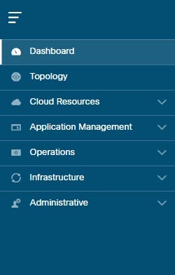
The left side of the GUI contains the Navigation pane, which collapses and expands. To expand the pane, hover your mouse icon over it or click the menu icon at the top. When you click the menu icon, the Navigation pane locks in the open position. To collapse it, click the menu icon again. When you expand the Navigation pane by hovering the mouse icon over the menu icon, you collapse the Navigation pane by moving the mouse icon away from it.

When expanded, the Navigation pane displays a list of tabs. When clicked, each tab displays a set of subtabs that enable you to navigate between the Cisco Cloud APIC component windows.

Figure 2. Navigation Pane (Expanded)

The Cisco Cloud APIC component windows are organized in the Navigation pane as follows:

  • Dashboard Tab—Displays summary information about the Cisco Cloud APIC components.

  • Topology Tab—Displays topology information about the Cisco Cloud APIC.

  • Cloud Resources Tab—Displays information about regions, VNETs, routers, security groups (application security groups/network security groups), endpoints, instances, and cloud services (and target groups).

  • Application Management Tab—Displays information about tenants, application profiles, EPGs, contracts, filters, VRFs, service graphs, devices, and cloud context profiles.

  • Operations Tab—Displays information about event analytics, active sessions, backup & restore policies, tech support policies, firmware management, schedulers, and remote locations.

  • Infrastructure Tab—Displays information about the system configuration, inter-region connectivity, and on-premises connectivity.

  • Administrative Tab—Displays information about authentication, event analytics, security, local and remote users, and smart licensing.

Note 

For more information about the contents of these tabs, see Viewing System Details

Figure 3. Search Menu-Bar Icon

The search menu-bar icon displays the search field, which enables you to to search for any object by name or any other distinctive fields.

Figure 4. Intent Menu-Bar Icon

The Intent icon appears in the menu bar between the search and the help icons.

When clicked, the Intent dialog appears (see below). The Intent dialog enables you to create a component from any window in the Cisco Cloud APIC GUI. When you create or view a component, a dialog box opens and hides the Intent icon. Close the dialog box to access the Intent icon again.

For more information about creating a component, see Configuring Cisco Cloud APIC Components.

Figure 5. Intent Dialog Box

The Intent (What do you want to do?) dialog box contains a search box and a drop-down list. The drop-down list enables you to apply a filter for displaying specific options. The search box enables you to enter text for searching through the filtered list.

Figure 6. Feedback Icon

The feedback icon appears in the menu bar between the Intent and the bookmark icons.

When clicked, the feedback panel appears.

Figure 7. Bookmark Icon

The bookmark icon appears in the menu bar between the feedback and the system tools icons.

When clicked, the current page is bookmarked on your system.

Figure 8. System Tools Menu-Bar Icon

The system tools menu-bar icon provides the following options:

  • About—Display the Cisco Cloud APIC version.

  • ObjectStore Browser—Open the Managed Object Browser, or Visore, which is a utility that is built into Cisco Cloud APIC that provides a graphical view of the managed objects (MOs) using a browser.

Figure 9. Help Menu-Bar Icon

The help menu-bar icon shows the About Cloud APIC menu option, which provides the version information for the Cloud APIC. The help menu-bar icon also shows the Help Center and Welcome Screen menu options.

Figure 10. User Profile Menu-Bar Icon

The user profile menu-bar icon provides the following options:

  • User Preferences—Allows you to set the time format (Local or UTC) and enable or disable the Welcome Screen at login.

  • Change Password—Enables you to change the password.

  • Change SSH Key—Enables you to change the SSH key.

  • Change User Certificate—Enables you to change the user certificate.

  • Logout—Enables you to log out of the GUI.