Overview
The Cisco Cloud APIC enables you to deploy Layer 4 to Layer 7 service devices to the public cloud. This initial release supports application load balancer (ALB) deployments in Amazon Web Services (AWS).
About Application Load Balancers
An application load balancer (ALB) is a Layer 7 load balancer that inspects packets and creates access points to HTTP and HTTPS headers. It also identifies the load and spreads it out to the targets with higher efficiency. You deploy an ALB using a service graph, which enables you to define how you want traffic to come into the network, the devices that the traffic passes through, and how the traffic leaves the network. You specify these actions by configuring one or more listeners.
Listeners enable you to specify the ports and protocols (HTTP or HTTPS) that the ALB accepts traffic on. When specifying HTTPS, you also choose a security policy and an SSL certificate.
 Note |
A listener can have multiple certificates. |
All listeners require you to configure at least one rule (a default rule, which does not have a condition). Rules enable you to specify the action that the load balancer takes when a condition is met. For example, you can create a rule that redirects traffic to a specified URL when a request is made to a specified hostname or path.
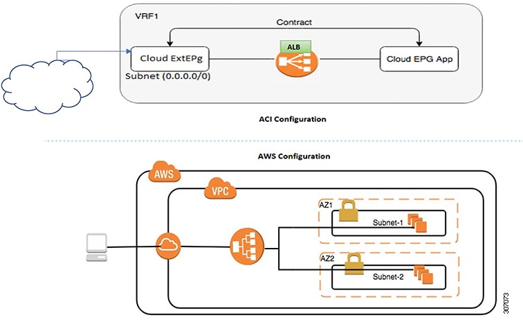
There are two deployment types: internet-facing and internal-facing. An internet-facing deployment inserts the ALB as a service between the consumer external EPG and the provider cloud EPG. The following figure shows the contract configuration within the VRF and the ALB as a service inserted between the consumer external EPG and the provider cloud EPG.

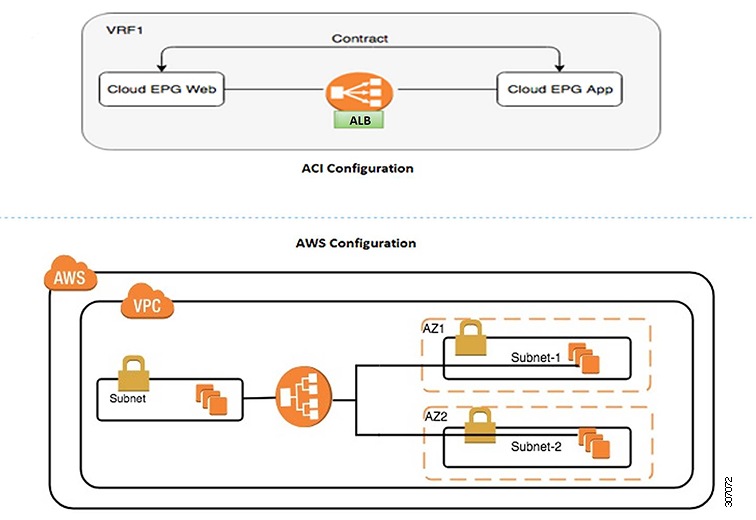
An internal-facing deployment inserts the ALB as a service between the consumer cloud EPG and the provider cloud EPG. The following figure shows the contract configuration within the VRF and the ALB as a service inserted between the consumer cloud EPG and provider cloud EPG.

 Note |
You can find more information about ALBs in the documentation on the AWS website. |
Dynamic Server Attachment to Server Pool
Servers in the server pool or target group are dynamically added. You do not need to specify the IP addresses or instance Ids for the targets. The relation from a listener rule to a provider cloud EPG is used for the dynamic selection of endpoints. The relation is also used for adding the endpoints to the target group. By default, the endpoints are registered with the port number 80.
Based on the target group-to-security group association that is provided in the ALB, and the EPG (security group) of the endpoint, the EC2 instance (server) is associated to the target group dynamically on the target group's default port. Alternatively, instead of registering the EC2 instance on the target group port, you can attach the custom port by specifying the ports in the following table:
|
Provider EPG |
Ports |
|---|---|
|
EPGMap:<Epg1DN> |
9090 |
|
EPGMap:<Epg2DN> |
9091, 9099 |
You can specify EPGMap:<EpgDN> as the tag and the list of ports to be registered on the target group as a list separated by commas.
About Service Graphs
The Cisco Application Centric Infrastructure (ACI) treats services as a part of an application. Any services that are required are treated as a service graph that is instantiated on the Cisco ACI fabric from the Cisco APIC. You define the service for the application while service graphs identify the set of network or service functions that the application needs.
A service graph represents the network using the following elements:
-
Function node—A function node represents a function that is applied to the traffic, such as a load balancer. A function within the service graph might require one or more parameters and have one or more connectors.
-
Terminal node—A terminal node enables input and output from the service graph.
-
Connector—A connector enables input and output from a node.
After the graph is configured, the Cisco APIC automatically configures the services according to the service function requirements that are specified in the service graph. The Cisco APIC also automatically configures the network according to the needs of the service function that is specified in the service graph, which does not require any change in the service device.
A service graph is represented as two or more tiers of an application with the appropriate service function inserted between them.
A service appliance (device) performs a service function within the graph. One or more service appliances might be required to render the services required by a graph. A single-service device can perform one or more service functions.
Service graphs and service functions have the following characteristics:
-
Traffic sent from specific endpoint groups can be redirected based on a policy.
-
Service graph redirection is directional. In other words, redirection can be applied to both traffic directions or either one of them.
-
Logical functions can be rendered on the appropriate device, based on the policy.
-
The service graph supports splits and joins of edges, and it does not restrict the administrator to linear service chains.
-
Traffic can be reclassified again in the network after a service appliance emits it.
By using a service graph, you can install a service, a load balancer, once and deploy it multiple times in different logical topologies. Each time the graph is deployed, Cisco ACI takes care of changing the configuration on the service device to enable the forwarding in the new logical topology.
About Function Nodes
A function node represents a single service function. A function node has function node connectors, which represent the network requirement of a service function.
A function node within a service graph requires the following parameters:
-
A tenant
-
A cloud context profile with subnets in two availability zones
Function parameters can be specified when the service graph is rendered. For example, if the function node is a load balancer, the listener and its rule can be specified for the function node at the time the graph is rendered.
About Terminal Nodes
Terminal nodes connect a service graph with the contracts. You can insert a service graph for the traffic between two application cloud EPGs by connecting the terminal node to a contract. Once connected, traffic between the consumer cloud EPG and provider cloud EPG of the contract is redirected to the service graph.
 Feedback