Configuring Cisco Cloud APIC Components

About Configuring the Cisco Cloud APIC

You create the Cisco Cloud APIC components using either the Cisco Cloud APIC GUI or the REST API. This section explains how to create configuration, application management, operations, and administrative components.


Note


Configuring the Cisco Cloud APIC Using the GUI

Creating a Tenant Using the Cisco Cloud APIC GUI

This section explains how to create a tenant using the Cisco Cloud APIC GUI.

Before you begin

  • You can create a tenant that is managed by the Cisco Cloud APIC or a tenant that is unmanaged. To establish a managed tenant, you must first obtain the Azure subscription ID from the Azure portal. You enter the subscription ID in the appropriate field of the Cisco Cloud APIC when creating the tenant. Before you can use the managed tenant, you must explicitly grant the Cisco Cloud APIC permission to manage the subscription. The steps for doing so are displayed in the Cisco Cloud APIC GUI during tenant creation. The steps for the infra tenant, however, are displayed in the infra tenant details view:

    1. Click the Navigation menu > Application Management subtab.

    2. Double-click the infra tenant.

    3. Click View Azure Role Assignment Command. The steps for granting the Cisco Cloud APIC permission to manage the subscription are displayed.


    Note

    For information about obtaining the Azure subscription ID, see the Microsoft Azure documentation.


  • Creating an unmanaged tenant requires obtaining a directory (Azure Tenant) ID, an Azure enterprise application ID, and a client secret from the enterprise application. For more information, see the Microsoft Azure documentation.


    Note

    Cloud APIC does not disturb Azure resources created by other applications or users. It only manages the Azure resources created by itself.


  • The required steps to explicitly grant the Cisco Cloud APIC permission to manage a given subscription are located in the Cisco Cloud APIC GUI. When creating a tenant, the steps are displayed after entering the client secret. For the infra tenant:

  • Cloud APIC enforces ownership checks to prevent deployment of policies in the same tenant-region combination done either intentionally or by mistake. For example, assume that Cloud APIC is deployed in Azure subscription IA1 in region R1. Now you want to deploy a tenant TA1 in region R2. This tenant deployment i.e. account-region combination TA1-R2 is now owned by IA1-R1. If another Cloud APIC attempts to manage the same tenant-region combination later (say Capic2 in Azure subscription IA2 deployed in region R3), this will not be allowed because the current owner for the deployment TA1-R2 is IA1-R1. In other words, only one account in one region can be managed by one Cloud APIC. Example below shows some valid and wrong deployment combinations.

    Capic1:
    IA1-R1: TA1-R1 - ok
            TA1-R2 - ok
     
    Capic2:
    IA1-R2: TA1-R1 - not allowed
            TA1-R3 - ok
     
    Capic3:
    IA2-R1: TA1-R1 - not allowed
            TA1-R4 - ok
            TA2-R4 - ok
  • Ownership enforcement is done using Azure Resource Groups. When a new tenant in subscription TA1 in region R2 is managed by Cloud APIC, a Resource Group CAPIC_TA1_R2 (e.g. CAPIC_123456789012__eastus2) is created in the subscription. This Resource Group has a resource tag AciOwnerTag with value IA1_R1_TA1_R2, assuming it was managed by Cloud APIC in subscription IA1 and deployed in region R1. If the AciOwnerTag mismatch happens, tenant-region management is aborted.

    Here is a summary of AciOwnerTag mismatch cases:

    • Initially Cloud APIC is installed in a subscription, and then taken down and Cloud APIC is installed in a different subscription. All existing tenant-region deployment will fail.

    • Another Cloud APIC is managing the same tenant-region.

    In ownership mismatch cases, retry (to setup tenant-region again) is not currently supported. As a workaround, if you are certain that no other Cloud APIC is managing the same tenant-region combination, logon to the tenant's Azure subscription and manually remove the affected Resource Group (for example: CAPIC_123456789012__eastus2). Next, reload Cloud APIC or delete and add the tenant again.

Procedure


Step 1

Click the Intent icon. The Intent menu appears.

Step 2

Click the drop-down arrow below the Intent search box and choose Application Management.

A list of Application Management options appear in the Intent menu.

Step 3

From the Application Management list in the Intent menu, click Create Tenant. The Create Tenant dialog box appears.

Step 4

Choose the appropriate options and enter the appropriate values in each field as listed in the following Create Tenant Dialog Box Fields table then continue.

Table 1. Create Tenant Dialog Box Fields

Properties

Description

Name

Enter the name of the tenant.

Description

Enter a description of the tenant.

Settings

Add Security Domain

To add a security domain for the tenant:

  1. Click Add Security Domain. The Select Security Domains dialog appears with a list of security domains in the left pane.

  2. Click to choose a security domain.

  3. Click Select to add the security domain to the tenant.

Azure Subscription

Mode

Choose an account type:

  • Create Own—Choose this option to create a new tenant.

  • Select Shared—Choose this option to inherit the managed or unmanaged settings from an existing tenant.

Azure Subscription ID

Enter the Azure subscription ID.

Access Type

Choose an access type:

  • Unmanaged Identity—Choose this option if the tenant subscription is not managed by the Cisco Cloud APIC.

  • Managed Identity—Choose this option if the tenant subscription is managed by the Cisco Cloud APIC. For more information, see Configuring a Tenant Azure Provider.

Application ID

Note 

This field is only valid for the Unmanaged Identity access type.

Enter the application ID.

Note 

For information about obtaining the application ID, see the Azure documentation or support.

Client Secret

Note 

This field is only valid for the Unmanaged Identity access type.

Enter the client secret.

Note 
  • For information about creating a client secret, see the Azure documentation or support.

  • You must explicitly grant Cloud APIC permission to manage a given subscription. Go to the Azure portal and follow these steps:

    1. Open the Cloud Shell

    2. Choose 'Bash'

    3. Copy and paste the command displayed in the Cisco Cloud APIC GUI.

Active Directory ID

Note 

This field is only valid for the Unmanaged Identity access type.

Enter the active directory ID.

Note 

For information about obtaining the active directory ID, see the Azure documentation or support.

Add Security Domain

To add a security domain for the account:

  1. Click Add Security Domain. The Select Security Domains dialog appears with a list of security domains in the left pane.

  2. Click to choose a security domain.

  3. Click Select to add the security domain to the tenant.

Step 5

Click Save when finished.


Creating an Application Profile Using the Cisco Cloud APIC GUI

This section explains how to create an application profile using the Cisco Cloud APIC GUI.

Before you begin

Create a tenant.

Procedure


Step 1

Click the Intent icon. The Intent menu appears.

Step 2

Click the drop-down arrow below the Intent search box and choose Application Management.

A list of Application Management options appear in the Intent menu.

Step 3

From the Application Management list in the Intent menu, click Create Application Profile. The Create Application Profile dialog box appears.

Step 4

Enter a name in the Name field.

Step 5

Choose a tenant:

  1. Click Select Tenant.

    The Select Tenant dialog box appears.

  2. From the Select Tenant dialog, click to choose a tenant in the left column then click Select.

    You return to the Create Application Profile dialog box.

Step 6

Enter a description in the Description field.

Step 7

Click Save when finished.


Creating a VRF Using the Cisco Cloud APIC GUI

This section explains how to create a VRF using the Cisco Cloud APIC GUI.

Before you begin

Create a tenant.

Procedure


Step 1

Click the Intent icon. The Intent menu appears.

Step 2

Click the drop-down arrow below the Intent search box and choose Application Management.

A list of Application Management options appear in the Intent menu.

Step 3

From the Application Management list in the Intent menu, click Create VRF. The Create VRF dialog box appears.

Step 4

Enter the appropriate values in each field as listed in the following Create VRF Dialog Box Fields table then continue.

Table 2. Create VRF Dialog Box Fields

Properties

Description

General

Name

Enter a name for the VRF in the Name field.

All VRFs are assigned a vrfEncoded value. If the Tenant and VRF name combination has more than 32 characters, then, a VRF name (which also contains the tenant name) is identified in the cloud router using the vrfEncoded value. To see the vrfEncoded value, navigate to Application Management > VRFs subtab. Click a VRF on the right hand pane and look for Encoded VRF Name in Cloud Router.

Tenant

To choose a tenant:

  1. Click Select Tenant. The Select Tenant dialog box appears.

  2. From the Select Tenant dialog, click to choose a tenant in the left column then click Select. You return to the Create VRF dialog box.

Description

Enter a description of the VRF.

Step 5

When finished, click Save.


Creating an EPG Using the Cisco Cloud APIC GUI

Use the procedures in this section to create an application EPG, an external EPG, or a service EPG. The available configuration options vary, depending on which type of EPG you are creating.

Creating an Application EPG Using the Cisco Cloud APIC GUI

This section explains how to create an application EPG using the Cisco Cloud APIC GUI. Each service needs at least one consumer EPG and one provider EPG.


Note

Beginning with Release 5.0(2), Cisco Cloud APIC creates the overlay-2 VRF in the infra tenant by default during the bring up, along with the overlay-1 VRF.

In addition, beginning with Release 5.0(2), you can create cloud EPGs and cloud external EPGs in the infra tenant, where all the cloud EPGs and cloud external EPGs will be associated with the overlay-2 VRF in the infra tenant. A cloud EPG in the overlay-2 VRF can communicate with other cloud EPGs and cloud external EPGs in the overlay-2 VRF, and can also communicate with cloud EPGS in other user tenant VRFs. We recommend that you do not use existing "cloud-infra" application profiles, and instead create a new application profile in the infra tenant and associate that new application profile to the cloud EPGs and cloud external EPGs in the overlay-2 VRF.


Before you begin

Create an application profile and a VRF.

Procedure


Step 1

Click the Intent icon.

The Intent menu appears.

Step 2

Click the drop-down arrow below the Intent search box and choose Application Management.

A list of Application Management options appear in the Intent menu.

Step 3

From the Application Management list in the Intent menu, click Create EPG.

The Create EPG dialog box appears.

Step 4

Enter the appropriate values in each field as listed in the following Create EPG Dialog Box Fields table then continue.

Table 3. Create EPG Dialog Box Fields

Properties

Description

General

Name

Enter the name of the EPG.

Tenant

To choose a tenant:

  1. Click Select Tenant. The Select Tenant dialog box appears.

  2. From the Select Tenant dialog, click to choose a tenant in the left column.

    Beginning with Release 5.0(2), you can select the infra tenant and can create cloud EPGs and cloud external EPGs in the infra tenant, as described earlier in this section.

  3. Click Select. You return to the Create EPG dialog box.

Application Profile

To choose an application profile:

  1. Click Select Application Profile. The Select Application Profile dialog box appears.

  2. From the Select Application Profile dialog, click to choose an application profile in the left column.

    Note 

    If you are creating an EPG in the infra tenant, we recommend that you do not choose the cloud-infra application profile because that application profile is used by EPGs in the overlay-1 VRF. Select a different application profile or click Create Application Profile to create a new one.

  3. Click Select. You return to the Create EPG dialog box.

Description

Enter a description of the EPG.

Settings

Type

Because this will be an application EPG, choose Application as the EPG type.

VRF

To choose a VRF:

  1. Click Select VRF. The Select VRF dialog box appears.

  2. From the Select VRF dialog, click to choose a VRF in the left column.

    If you are creating an EPG in the infra tenant, select the overlay-2 VRF in this step. A cloud EPG in the overlay-2 VRF can communicate with other cloud EPGs and cloud external EPGs in the overlay-2 VRF, and can also communicate with cloud EPGs in other user tenant VRFs.

  3. Click Select. You return to the Create EPG dialog box.

Endpoint Selectors

Note 

See Configuring Virtual Machines in Azure for instructions on configuring virtual machines in Azure as part of the endpoint selector configuration process.

To add an endpoint selector:

  1. Click Add Endpoint Selector to open the Add Endpoint Selector dialog.

  2. In the Add Endpoint Selector dialog, enter a name in the Name field.

  3. Click Selector Expression. The Key, Operator, and Value fields are enabled.

  4. Click the Key drop-down list to choose a key. The options are:

    • Choose IP if you want to use an IP address or subnet for the endpoint selector.

      Note 

      IPv6 is not supported for Cisco Cloud APIC in Azure. You must use a valid IPv4 address for this field.

    • Choose Region if you want to use the Azure region for the endpoint selector.

    • Choose Custom if you want to create a custom key for the endpoint selector.

      Note 

      When choosing the Custom option, the drop-down list becomes a text box. You need to enter a name for the key in the spaces after custom: (for example, custom: Location).

  5. Click the Operator drop-down list to choose an operator. The options are:

    • equals: Used when you have a single value in the Value field.

    • not equals: Used when you have a single value in the Value field.

    • in: Used when you have multiple comma-separated values in the Value field.

    • not in: Used when you have multiple comma-separated values in the Value field.

    • has key: Used if the expression contains only a key.

    • does not have key: Used if the expression contains only a key.

  6. Enter a value in the Value field then click the check mark to validate the entries. The value you enter depends on the choices you made for the Key and Operator fields. For example, if the Key field is set to IP and the Operator field is set to equals, the Value field must be an IP address or subnet. However, if the Operator field is set to has key, the Value field is disabled.

  7. When finished, click the check mark to validate the selector expression.

  8. Determine if you want to create additional endpoint selector expressions to the endpoint selector. If you create more than one expression under a single endpoint selector, a logical AND exists between those expressions.

    For example, assume you created two sets of expressions under a single endpoint selector:

    • Endpoint selector 1, expression 1:

      • Key: Region

      • Operator: equals

      • Value: westus

    • Endpoint selector 1, expression 2:

      • Key: IP

      • Operator: equals

      • Value: 192.0.2.1/24

    In this case, if both of these expressions are true (if the region is westus AND if the IP address belongs to subnet 192.0.2.1/24), then that endpoint is assigned to the Cloud EPG.

  9. Click the check mark after every additional expression that you want to create under this endpoint selector then click Add when finished.

    If you create more than one endpoint selector under an EPG, a logical OR exists between those endpoint selectors. For example, assume you had created endpoint selector 1 as described in the previous step, and then you created a second endpoint selector as described below:

    • Endpoint selector 2, expression 1:

      • Key: Region

      • Operator: in

      • Value: eastus, centralus

    In this case:

    • If the region is westus AND the IP address belongs to the 192.0.2.1/24 subnet (endpoint selector 1 expressions)

      OR

    • If the region is either eastus or centralus (endpoint selector 2 expression)

    Then that end point is assigned to the Cloud EPG.

Step 5

Click Save when finished.


Creating an External EPG Using the Cisco Cloud APIC GUI

This section explains how to create an external EPG using the Cisco Cloud APIC GUI. Each service needs at least one consumer EPG and one provider EPG.


Note

Beginning with Release 5.0(2), Cisco Cloud APIC creates the overlay-2 VRF in the infra tenant by default during the bring up, along with the overlay-1 VRF.

In addition, beginning with Release 5.0(2), you can create cloud EPGs and cloud external EPGs in the infra tenant, where all the cloud EPGs and cloud external EPGs will be associated with the overlay-2 VRF in the infra tenant. A cloud EPG in the overlay-2 VRF can communicate with other cloud EPGs and cloud external EPGs in the overlay-2 VRF, and can also communicate with cloud EPGS in other user tenant VRFs. We recommend that you do not use existing "cloud-infra" application profiles, and instead create a new application profile in the infra tenant and associate that new application profile to the cloud EPGs and cloud external EPGs in the overlay-2 VRF.


Before you begin

Create an application profile and a VRF.

Procedure


Step 1

Click the Intent icon.

The Intent menu appears.

Step 2

Click the drop-down arrow below the Intent search box and choose Application Management.

A list of Application Management options appear in the Intent menu.

Step 3

From the Application Management list in the Intent menu, click Create EPG.

The Create EPG dialog box appears.

Step 4

Enter the appropriate values in each field as listed in the following Create EPG Dialog Box Fields table then continue.

Table 4. Create EPG Dialog Box Fields

Properties

Description

General

Name

Enter the name of the EPG.

Tenant

To choose a tenant:

  1. Click Select Tenant. The Select Tenant dialog box appears.

  2. From the Select Tenant dialog, click to choose a tenant in the left column.

    Beginning with Release 5.0(2), you can select the infra tenant and can create cloud EPGs and cloud external EPGs in the infra tenant, as described earlier in this section.

  3. Click Select. You return to the Create EPG dialog box.

Application Profile

To choose an application profile:

  1. Click Select Application Profile. The Select Application Profile dialog box appears.

  2. From the Select Application Profile dialog, click to choose an application profile in the left column.

    Note 

    If you are creating an EPG in the infra tenant, we recommend that you do not choose the cloud-infra application profile because that application profile is used by EPGs in the overlay-1 VRF. Select a different application profile or click Create Application Profile to create a new one.

  3. Click Select. You return to the Create EPG dialog box.

Description

Enter a description of the EPG.

Settings

Type

Because this will be an external EPG, choose External as the EPG type.

VRF

To choose a VRF:

  1. Click Select VRF. The Select VRF dialog box appears.

  2. From the Select VRF dialog, click to choose a VRF in the left column.

    If you are creating an EPG in the infra tenant, select the overlay-2 VRF in this step. A cloud EPG in the overlay-2 VRF can communicate with other cloud EPGs and cloud external EPGs in the overlay-2 VRF, and can also communicate with cloud EPGs in other user tenant VRFs.

  3. Click Select. You return to the Create EPG dialog box.

Route Reachability

Choose the type of route reachability for the external EPG. The options are:

  • Internet

  • External-Site

Endpoint Selectors

Note 

See Configuring Virtual Machines in Azure for instructions on configuring virtual machines in Azure as part of the endpoint selector configuration process.

To add an endpoint selector:

  1. Click Add Endpoint Selector to add an endpoint selector.

  2. Enter a name in the Name field.

  3. Enter a subnet in the Subnet.

    Note 

    IPv6 is not supported for Cisco Cloud APIC in Azure. You must use a valid IPv4 address for this field.

  4. When finished, click the check mark to validate the endpoint selector.

  5. Determine if you want to create additional endpoint selectors.

    If you create more than one endpoint selector under an EPG, a logical OR exists between those endpoint selectors. For example, assume you created two endpoint selectors:

    • Endpoint selector 1:

      • Name: EP_Sel_1

      • Subnet: 192.1.1.1/24

    • Endpoint selector 2:

      • Name: EP_Sel_2

      • Subnet: 192.2.2.2/24

    In this case:

    • If the IP address belongs to the 192.1.1.1/24 subnet (endpoint selector 1)

      OR

    • If the IP address belongs to the 192.2.2.2/24 subnet (endpoint selector 2)

    Then that end point is assigned to the Cloud EPG.

Step 5

Click Save when finished.


Creating a Service EPG

Use the procedures in the following sections to create a service EPG.

Tasks To Perform Prior to Configuring Service EPGs

Before you can configure a service EPG, there are certain tasks that you might have to perform beforehand. If you are using subnets or private link labels with your service EPG, you must first configure the subnets and/or private link label outside of the service EPG.

Procedure

Step 1

Create a VRF, if necessary.

  1. Click the Intent icon. The Intent menu appears.

  2. Click the drop-down arrow below the Intent search box and choose Application Management.

    A list of Application Management options appear in the Intent menu.

  3. From the Application Management list in the Intent menu, click Create VRF. The Create VRF dialog box appears.

  4. Make the following selections:

    • Name: Enter the name for the VRF.

    • Tenant: Select a tenant.

  5. Click Save.

Step 2

Configure a cloud context profile.

  1. Click the Intent icon. The Intent menu appears.

  2. Click the drop-down arrow below the Intent search box and choose Application Management.

    A list of Application Management options appear in the Intent menu.

  3. From the Application Management list in the Intent menu, click Create Cloud Context Profile. The Create Cloud Context Profile dialog box appears.

Step 3

Enter the appropriate values in each field as listed in the following Cloud Context Profile Dialog Box Fields table then continue.

Table 5. Create Cloud Context Profile Dialog Box Fields

Properties

Description

Name

Enter the name of the cloud context profile.

Tenant

To choose a tenant:

  1. Click Select Tenant. The Select Tenant dialog box appears.

  2. From the Select Tenant dialog, click to choose a tenant in the left column then click Select. You return to the Create Cloud Context Profile dialog box.

Description

Enter a description of the cloud context profile.

Settings

Region

To choose a region:

  1. Click Select Region. The Select Region dialog box appears.

  2. From the Select Region dialog, click to choose a region in the left column then click Select. You return to the Create Cloud Context Profile dialog box.

VRF

To choose a VRF:

  1. Click Select VRF. The Select VRF dialog box appears.

  2. From the Select VRF dialog box, click to choose a VRF in the left column then click Select. You return to the Create Cloud Context Profile dialog box.

Add CIDR

Note 

You cannot add, delete, or edit a CIDR when VNet peering is enabled. You must disable VNet peering before adding, deleting or editing a CIDR. To disable VNet peering:

  • For the infra tenant, disable the Hub Network Peering option in the cloud context profile

  • For a user (non-infra) tenant, disable the VNet Peering option in the cloud context profile

Enable VNet peering again after you have made the changes to the CIDR configuration.

The following features are supported, depending on the release:

  • Beginning in Release 5.0(2), you can add additional secondary CIDRs and subnets for infra VNets (cloudCtxProfiles created by the cloud template). You cannot add primary CIDRs or modify the existing CIDRs created by the cloud template. After subnets are created under the user-created CIDRs, the subnets will be implicitly mapped to the overlay-2 VRF.

  • Beginning with Release 5.1(2), you can add also additional secondary CIDRs and subnets for VNets other than the infra VNet.

See Support for Multiple VRFs Under Single VNet for more information.

To add a CIDR:

  1. Click Add CIDR. The Add CIDR dialog box appears.

  2. Enter the address in the CIDR Block Range field.

  3. Click to check (enabled) or uncheck (disabled) the Primary check box.

    If you are adding additional secondary CIDRs and subnets for VNets, leave the Primary box unchecked.

  4. Click Add Subnet and enter the following information:

    • In the Address field, enter the subnet address.

    • In the Name field, enter the name for this subnet.

    • In the Private Link Label field, choose Create New and enter a unique name for the private link label to associate with this subnet.

  5. In the VRF field, make a selection, if necessary.

    • If you checked the box next to the Primary field, this CIDR is automatically associated with the primary VRF.

    • If you did not check the box next to the Primary field, you can associate this CIDR with a secondary VRF. Click the X next to the VRF, then click on Select VRF to select the secondary VRF to associate with this CIDR.

  6. When finished, click Add.

VNet Gateway Router

Click to check (enable) or uncheck (disable) in the VNet Gateway Router check box.

VNet Peering

Click to check (enable) or uncheck (disable) the Azure VNet peering feature.

For more information on the VNet peering feature, see the Configuring VNet Peering for Cloud APIC for Azure document in the Cisco Cloud APIC documentation page.

Step 4

Click Save.


Creating a Service EPG Using the Cisco Cloud APIC GUI

This section explains how to create a service EPG using the Cisco Cloud APIC GUI. Each service needs at least one consumer EPG and one provider EPG.

Before you begin
  • Review the information in Cloud Service Endpoint Groups.

  • Verify that you have the NSG-per-subnet configuration enabled.

    You must have the NSG-per-subnet configuration enabled if you are configuring cloud service EPGs. See Security Groups for more information.

  • Create an application profile and a VRF.

Procedure

Step 1

Click the Intent icon.

The Intent menu appears.

Step 2

Click the drop-down arrow below the Intent search box and choose Application Management.

A list of Application Management options appear in the Intent menu.

Step 3

From the Application Management list in the Intent menu, click Create EPG.

The Create EPG dialog box appears.

Step 4

Enter the appropriate values in each field as listed in the following Create EPG Dialog Box Fields table then continue.

Table 6. Create EPG Dialog Box Fields

Properties

Description

General

Name

Enter the name of the EPG.

Tenant

To choose a tenant:

  1. Click Select Tenant. The Select Tenant dialog box appears.

  2. From the Select Tenant dialog, click to choose a tenant in the left column.

  3. Click Select. You return to the Create EPG dialog box.

Application Profile

To choose an application profile:

  1. Click Select Application Profile. The Select Application Profile dialog box appears.

  2. From the Select Application Profile dialog, click to choose an application profile in the left column.

    Note 

    If you are creating a service EPG in the infra tenant, we recommend that you do not choose the cloud-infra application profile because that application profile is used by EPGs in the overlay-1 VRF. Select a different application profile or click Create Application Profile to create a new one.

  3. Click Select. You return to the Create EPG dialog box.

Description

Enter a description of the EPG.

Settings

Type

Because this will be a service EPG, choose Service as the EPG type.

VRF

To choose a VRF:

  1. Click Select VRF. The Select VRF dialog box appears.

  2. From the Select VRF dialog, click to choose a VRF in the left column.

  3. Click Select. You return to the Create EPG dialog box.

Deployment Type

Choose the EPG deployment type.

Services are differentiated based on their deployment mode:

  • Cloud Native: A Cloud Native service deployed in the provider network

  • Cloud Native Managed: A Cloud Native service deployed in your network

  • Third-Party: A third-party service from the market place

Access Type

Choose the EPG deployment access type. The access type indicates how the other services or VMs will connect to the service.

The choices vary, depending on the selection you made in the Deployment Type field:

  • Cloud Native deployment type:

    • Public: Access the public IP of the service.

    • Private: Use private links and private endpoints to access the service.

  • Cloud Native Managed deployment type:

    • Private: Choose this type if the service deployed in the managed subnet has only private IP addresses.

    • Public and Private: Use public and private endpoints to access the service. This is used for services that also expose public IP addresses when deployed in Cisco Cloud APIC-managed subnets.

  • Third-Party deployment type: Private is the only option available to you as an access type. This means that you will use only private endpoints to the service, if the service offers it.

Service Type

Choose the Azure service type.

Certain service types are only supported with certain specific deployment types. See Cloud Service Endpoint Groups for more information on the service types that are supported with specific deployment types.

The options are:

Step 5

Enter the necessary information in the Endpoint Selector area, depending on the selection you made in the Deployment Type field:


Configuring Cloud Native as the Deployment Type

Use the procedures in this section to configure Cloud Native as the deployment type for the service EPG.

Before you begin

Review the information provided in Cloud Native to understand tasks that you might have to perform prior to using these instructions.

Procedure

Step 1

Verify that you have completed the steps in Creating a Service EPG Using the Cisco Cloud APIC GUI before beginning these procedures.

These procedures are a continuation of the procedures provided in Creating a Service EPG Using the Cisco Cloud APIC GUI, where you would have set a service type, such as Azure SQL, before configuring the deployment type in these procedures.

Step 2

If you selected Private as the access type, the Select Private Link Label option becomes available.

A private link label is used to associate the subnets to the service EPGs.

Step 3

Click Select Private Link Label.

The Select Private Link Label window appears.

Step 4

Search for the appropriate private link label.

Search for the private link label that you created using the procedures provided in Tasks To Perform Prior to Configuring Service EPGs.

Step 5

In the Select Private Link Label window, select the appropriate private link label.

You are returned to the Create EPG window.

Next, add an endpoint selector in the Endpoint Selectors field.

Step 6

Click Add Endpoint Selector.

The Add Endpoint Selector window appears.

Step 7

In the Add Endpoint Selector window, enter a name in the Name field.

Step 8

Click the Key drop-down list to choose a key.

The options are:

  • Choose Custom if you want to create a custom endpoint selector.

  • Choose Region if you want to use the Azure region for the endpoint selector.

  • Choose Name if you want to use the service resource's name for the endpoint selector.

    For example, to select an SQL server with the name ProdSqlServer, you would choose Name in the Key field, and you would enter ProdSqlServer in the Value field later in these procedures.

  • Choose Resource ID if you want to use the cloud provider's ID for the endpoint selector.

    For example, to select an SQL server using the cloud provider's resource ID, you would choose Resouce ID in the Key field, and you would enter the value of the selector, such as /subscriptions/{subscription-id}/resourceGroups/{resourceGroupName}/providers/Microsoft.Sql/servers/ProdSqlServer, in the Value field later in these procedures.

Step 9

Click the Operator drop-down list to choose an operator.

The options are:

  • equals: Used when you have a single value in the Value field.

  • not equals: Used when you have a single value in the Value field.

  • in: Used when you have multiple comma-separated values in the Value field.

  • not in: Used when you have multiple comma-separated values in the Value field.

  • has key: Used if the expression contains only a key.

  • does not have key: Used if the expression contains only a key.

Step 10

Enter a value in the Value field then click the check mark to validate the entries.

The value you enter depends on the choices you made for the Key and Operator fields.

For example, if the Key field is set to IP and the Operator field is set to equals, the Value field must be an IP address or subnet. However, if the Operator field is set to has key, the Value field is disabled.

Step 11

When finished, click the check mark to validate the selector expression.

Step 12

Determine if you want to create additional endpoint selector expressions for the endpoint selector.

If you create more than one expression under a single endpoint selector, a logical AND exists between those expressions.

For example, assume you created two sets of expressions under a single endpoint selector:

  • Endpoint selector 1, expression 1:

    • Key: Region

    • Operator: equals

    • Value: westus

  • Endpoint selector 1, expression 2:

    • Key: Name

    • Operator: equals

    • Value: ProdSqlServer

In this case, if both of these expressions are true (if the region is westus AND if the name attached to the resource is ProdSqlServer), then that endpoint is assigned to the service EPG.

Step 13

Click the check mark after every additional expression that you want to create under this endpoint selector, then click Add when finished.

You are returned to the Create EPG screen, with the new endpoint selector and the configured expressions shown.

Step 14

If you want to create additional endpoint selectors, click Add Endpoint Selector again and repeat these steps to create additional endpoint selectors.

If you create more than one endpoint selector under an EPG, a logical OR exists between those endpoint selectors. For example, assume you had created endpoint selector 1 as described in the previous step, and then you created a second endpoint selector as described below:

  • Endpoint selector 2, expression 1:

    • Key: Region

    • Operator: in

    • Value: eastus, centralus

In this case:

  • If the region is westus AND the name attached to the resource is ProdSqlServer (endpoint selector 1 expressions)

    OR

  • If the region is either eastus or centralus (endpoint selector 2 expression)

Then that end point is assigned to the service EPG.

Step 15

Click Save when finished.


Configuring Cloud Native Managed as the Deployment Type

Use the procedures in this section to configure Cloud Native Managed as the deployment type for the service EPG.

Before you begin

Review the information provided in Cloud Native Managed to understand tasks that you might have to perform prior to using these instructions.

Procedure

Step 1

Verify that you have completed the steps in Creating a Service EPG Using the Cisco Cloud APIC GUI before beginning these procedures.

These procedures are a continuation of the procedures provided in Creating a Service EPG Using the Cisco Cloud APIC GUI, where you would have set a service type, such as Azure ApiManagement Services, before configuring the deployment type in these procedures.

Step 2

Click Add Endpoint Selector.

The Add Endpoint Selector window appears.

Step 3

In the Add Endpoint Selector window, enter a name in the Name field.

Step 4

Click the Key drop-down list to choose a key.

At this time, IP is the only option available as a key for this access type.

Note 

IPv6 is not supported for Cisco Cloud APIC in Azure. You must use a valid IPv4 address for this field.

Step 5

Click the Operator drop-down list to choose an operator.

The options are:

  • equals: Used when you have a single value in the Value field.

  • not equals: Used when you have a single value in the Value field.

  • in: Used when you have multiple comma-separated values in the Value field.

  • not in: Used when you have multiple comma-separated values in the Value field.

  • has key: Used if the expression contains only a key.

  • does not have key: Used if the expression contains only a key.

Step 6

Enter the appropriate IP address or a subnet in the Value field then click the check mark to validate the entries.

Enter the IP address or subnet that you created using the procedures provided in Tasks To Perform Prior to Configuring Service EPGs.

Step 7

When finished, click the check mark to validate the selector expression.

Step 8

Determine if you want to create additional endpoint selector expressions to the endpoint selector.

If you create more than one expression under a single endpoint selector, a logical AND exists between those expressions.

For example, assume you created two sets of expressions under a single endpoint selector:

  • Endpoint selector 1, expression 1:

    • Key: IP

    • Operator: equals

    • Value: 192.1.1.1/24

  • Endpoint selector 1, expression 2:

    • Key: IP

    • Operator: not equals

    • Value: 192.1.1.2

In this case, if both of these expressions are true (if the IP address belongs to subnet 192.1.1.1/24 AND the IP address is not 192.1.1.2), then that endpoint is assigned to the service EPG.

Step 9

Click the check mark after every additional expression that you want to create under this endpoint selector, then click Add when finished.

You are returned to the Create EPG screen, with the new endpoint selector and the configured expressions shown.

Step 10

If you want to create additional endpoint selectors, click Add Endpoint Selector again and repeat these steps to create additional endpoint selectors.

If you create more than one endpoint selector under an EPG, a logical OR exists between those endpoint selectors. For example, assume you had created endpoint selector 1 as described in the previous step, and then you created a second endpoint selector as described below:

  • Endpoint selector 2, expression 1:

    • Key: IP

    • Operator: equals

    • Value: 192.2.2.2/24

In this case:

  • If the IP address belongs to subnet 192.1.1.1/24 AND the IP address is not 192.1.1.2 (endpoint selector 1 expressions)

    OR

  • If the IP address belongs to subnet 192.2.2.2/24

Then that end point is assigned to the service EPG.

Step 11

Click Save when finished.


Configuring Third-Party as the Deployment Type

Use the procedures in this section to configure Third-Party as the deployment type for the service EPG.


Note

You must choose Custom as the Service Type if you choose Third-Party as the Deployment Type.


Procedure

Step 1

Verify that you have completed the steps in Creating a Service EPG Using the Cisco Cloud APIC GUI before beginning these procedures.

These procedures are a continuation of the procedures provided in Creating a Service EPG Using the Cisco Cloud APIC GUI, where you would have set the service type as Custom Service before configuring the deployment type in these procedures.

Step 2

Make the necessary selections for the access type for the Third-Party deployment type.

Private is the only option available to you as an access type. This means that you will use only private endpoints to the service, if the service offers it.

The Select Private Link Label option becomes available with this access type. A private link label is used to associate the subnets to the service EPGs.

Step 3

Search for the appropriate private link label.

Search for the private link label that you created using the procedures provided in Tasks To Perform Prior to Configuring Service EPGs.

Step 4

In the Select Private Link Label window, select the appropriate private link label.

You are returned to the Create EPG window.

Next, add an endpoint selector in the Endpoint Selectors field.

Step 5

Click Add Endpoint Selector.

The Add Endpoint Selector window appears.

Step 6

In the Add Endpoint Selector window, enter a name in the Name field.

Step 7

Click the Key drop-down list to choose a key.

At this time, URL is the only option available as a key for this access type, where you will use the alias or fully qualified domain name (FQDN) that identifies the service for the endpoint selector.

Step 8

Click the Operator drop-down list to choose an operator.

The options are:

  • equals: Used when you have a single value in the Value field.

  • not equals: Used when you have a single value in the Value field.

  • in: Used when you have multiple comma-separated values in the Value field.

  • not in: Used when you have multiple comma-separated values in the Value field.

  • has key: Used if the expression contains only a key.

  • does not have key: Used if the expression contains only a key.

Step 9

Enter a valid URL in the Value field then click the check mark to validate the entries.

Step 10

When finished, click the check mark to validate the selector expression, then click Add.

You are returned to the Create EPG screen, with the new endpoint selector and the configured expression shown.

Step 11

If you want to create additional endpoint selectors, click Add Endpoint Selector again and repeat these steps to create additional endpoint selectors.

If you create more than one endpoint selector under an EPG, a logical OR exists between those endpoint selectors.

For example, assume you created two endpoint selectors as described below:

  • Endpoint selector 1:

    • Key: URL

    • Operator: equals

    • Value: www.acme1.com

  • Endpoint selector 2:

    • Key: URL

    • Operator: equals

    • Value: www.acme2.com

In this case:

  • If the URL is www.acme1.com

    OR

  • If the URL is www.acme2.com

Then that end point is assigned to the service EPG.

Step 12

Click Save when finished.


Creating a Filter Using the Cisco Cloud APIC GUI

This section explains how to create a filter using the Cisco Cloud APIC GUI.

Procedure


Step 1

Click the Intent icon. The Intent menu appears.

Step 2

Click the drop-down arrow below the Intent search box and choose Application Management.

A list of Application Management options appear in the Intent menu.

Step 3

From the Application Management list in the Intent menu, click Create Filter. The Create Filter dialog box appears.

Step 4

Enter the appropriate values in each field as listed in the following Create Filter Dialog Box Fields table then continue.

Table 7. Create Filter Dialog Box Fields

Properties

Description

Name

Enter a name for the filter in the Name field.

Tenant

To choose a tenant:

  1. Click Select Tenant. The Select Tenant dialog box appears.

  2. From the Select Tenant dialog, click to choose a tenant in the left column then click Select. You return to the Create Filter dialog box.

Description

Enter a description of the filter.

Add Filter

To add a filter:

  1. Click Add Filter Entry. The Add Filter Entry dialog box appears.

  2. Enter a name for the filter entry in the Name field.

  3. Click the Ethernet Type drop-down list to choose an ethernet type. The options are:

    • IP

    • Unspecified

      Note 

      When Unspecified is chosen, any traffic type is alloed, including IP, and the remaining fields are disabled.

  4. Click the IP Protocol drop-down menu to choose a protocol. The options are:

    • tcp

    • udp

    • Unspecified

      Note 

      The remaining fields are enabled only when tcp or udp is chosen.

  5. Enter the appropriate port range information in the Destination Port fields.

  6. When finished entering filter entry information, click Add. You return to the Create Filter dialog box where you can repeat the steps to add another filter entry.

Step 5

When finished, click Save.


Creating a Contract Using the Cisco Cloud APIC GUI

This section explains how to create a contract using the Cisco Cloud APIC GUI.

Before you begin

Create filters.

Procedure


Step 1

Click the Intent icon. The Intent menu appears.

Step 2

Click the drop-down arrow below the Intent search box and choose Application Management.

A list of Application Management options appear in the Intent menu.

Step 3

From the Application Management list in the Intent menu, click Create Contract. The Create Contract dialog box appears.

Step 4

Enter the appropriate values in each field as listed in the following Create Contract Dialog Box Fields table then continue.

Table 8. Create Contract Dialog Box Fields

Properties

Description

Name

Enter the name of the contract.

Tenant

To choose a tenant:

  1. Click Select Tenant. The Select Tenant dialog box appears.

  2. From the Select Tenant dialog, click to choose a tenant in the left column.

    Note 

    Beginning in Release 5.0(2), you can create contracts in the infra tenant. You can also export contracts from and import contracts to the infra tenant for shared services use cases.

  3. Click Select. You return to the Create Contract dialog box.

Description

Enter a description of the contract.

Settings

Scope

The scope limits the contract to any endpoint groups within the same application profile, within the same VRF instance, throughout the fabric (globally), or within the same tenant.

Note 

Shared services enables communication between EPGs in different tenants and between EPGs in different VRFs.

To enable EPGs in one tenant to communicate with EPGs in another tenant, choose Global scope.

To enable an EPG in one VRF to communicate with another EPG in a different VRF, choose Global or Tenant scope.

For more information about shared services, see Shared Services.

Click the drop-down arrow to choose from the following scope options:

  • Application Profile

  • VRF

  • Global

  • Tenant

Add Filter

To choose a filter:

  1. Click Add Filter. The filter row appears with a Select Filter option.

  2. Click Select Filter. The Select Filter dialog box appears.

  3. From the Select Filter dialog, click to choose a filter in the left column then click Select. You return to the Create Contract dialog box.

Step 5

Click Save when finished.


Creating an Inter-Tenant Contract Using the Cisco Cloud APIC GUI

This section explains how to create an inter-tenant contract using the Cisco Cloud APIC GUI. See Shared Services for more information on situations where you might want to create an inter-tenant contract.

Before you begin

Create filters.

Procedure


Step 1

Click the Intent icon. The Intent menu appears.

Step 2

Click the drop-down arrow below the Intent search box and choose Application Management.

A list of Application Management options appear in the Intent menu.

Step 3

From the Application Management list in the Intent menu, click Create Contract. The Create Contract dialog box appears.

Step 4

Enter the appropriate values in each field as listed in the following Create Contract Dialog Box Fields table then continue.

Table 9. Create Contract Dialog Box Fields

Properties

Description

Name

Enter the name of the contract.

Tenant

To choose a tenant:

  1. Click Select Tenant. The Select Tenant dialog box appears.

  2. From the Select Tenant dialog, click to choose a tenant in the left column.

    Note 

    Beginning in Release 5.0(2), you can create contracts in the infra tenant. You can also export contracts from and import contracts to the infra tenant for shared services use cases.

  3. Click Select. You return to the Create Contract dialog box.

Description

Enter a description of the contract.

Settings

Scope

The scope limits the contract to any endpoint groups within the same application profile, within the same VRF instance, throughout the fabric (globally), or within the same tenant.

For inter-tenant communication, you will first create a contract with the Global scope in one of the tenants (for example, tenant1). This tenant’s EPG will always be the provider of this contract.

This contract will then be exported to the other tenant (for example, tenant2). For the other tenant that imports this contract, its EPG will be the consumer of the imported contract. If you want tenant2’s EPG to be the provider and tenant1’s EPG to be the consumer, then create a contract in tenant2 and then export it to tenant1.

Add Filter

To choose a filter:

  1. Click Add Filter. The filter row appears with a Select Filter option.

  2. Click Select Filter. The Select Filter dialog box appears.

  3. From the Select Filter dialog, click to choose a filter in the left column then click Select. You return to the Create Contract dialog box.

Step 5

Click Save when finished.

Step 6

Export the contract that you just created to another tenant.

For example, assume the following:

  • The contract that you created in the procedure above is named contract1 in tenant tenant1.

  • The contract that you want to export is named exported_contract1 and you are exporting it to tenant tenant2.

  1. Navigate to the Contracts page (Application Management > Contracts).

    The configured contracts are listed.

  2. Select the contract that you just created.

    For example, scroll through the list until you see the contract contract1 and click the box next to it to select it.

  3. Go to Actions > Export Contract.

    The Export Contract window appears.

  4. Click Select Tenant.

    The Select Tenant window appears.

  5. Select the tenant that you want to export the contract to, then click Save.

    For example, tenant2. You are returned to the Export Contract window.

  6. In the Name field, enter a name for the exported contract.

    For example, exported_contract1.

  7. In the Description field, enter a description for the exported contract, if necessary.

  8. Click Save.

    The list of contracts appears again.

Step 7

Configure the first tenant's EPG as the provider EPG, with the original contract, as the first part of the EPG communication configuration.

  1. Click the Intent button, then choose EPG Communication.

    The EPG Communication window appears.

  2. Click Let's Get Started.

  3. In the Contract area, click Select Contract.

    The Select Contract window appears.

  4. Locate and select the contract that you created at the beginning of these procedures.

    In this example, you would locate and select contract1.

  5. Click Select.

    The EPG Communication window appears.

  6. In the Provider EPGs area, click Add Provider EPGs.

    The Select Provider EPGs window appears.

  7. Leave the Keep selected items box checked, then select the first tenant's (tenant1) EPG.

  8. Click Select.

    The EPG Communication window appears.

  9. Click Save.

Step 8

Configure the second tenant's EPG as the consumer EPG, with the exported contract, as the second part of the EPG communication configuration.

  1. Click the Intent button, then choose EPG Communication.

    The EPG Communication window appears.

  2. Click Let's Get Started.

  3. In the Contract area, click Select Contract.

    The Select Contract window appears.

  4. Locate and select the contract that you created at the beginning of these procedures.

    In this example, you would locate and select exported_contract1.

  5. Click Select.

    The EPG Communication window appears.

  6. In the Consumer EPGs area, click Add Consumer EPGs.

    The Select Consumer EPGs window appears.

  7. Leave the Keep selected items box checked, then select the second tenant's (tenant2) EPG.

  8. Click Select.

    The EPG Communication window appears.

  9. Click Save.


Configuring Network Security Groups Using the Cloud APIC GUI

As described in Security Groups, the way the network security groups are configured differ, depending on the release:

  • For releases prior to Release 5.1(2), there is a one-to-one mapping between NSGs in Azure and EPGs on Cisco Cloud APIC (these configurations are also referred to as NSG-per-EPG configurations throughout this document).

  • Beginning with Release 5.1(2), in addition to the existing NSG-per-EPG configurations available previously, NSGs in Azure can also have a one-to-one mapping with subnets rather than EPGs on Cisco Cloud APIC (these configurations are also referred to as NSG-per-subnet configurations throughout this document).


Note

You can have either the newer NSG-per-subnet configuration or the older NSG-per-EPG configuration in your Cisco Cloud APIC. You cannot have both configurations in the same Cisco Cloud APIC system.


These procedures describe how to select either the newer NSG-per-subnet configuration or the older NSG-per-EPG configuration for your Cisco Cloud APIC for Release 5.1(2) or later.

Before you begin

Review the information provided in Security Groups to better understand how security groups are configured, depending on the release, and to understand the guidelines and limitations for security groups.

Procedure


Step 1

Log in to the Cloud APIC, if you are not logged in already.

Step 2

In the left navigation bar, navigate to Infrastructure > System Configuration.

The General tab is displayed by default.

Step 3

In the General area in the System Configuration window, locate the Network Security Group at Subnet Level field.

Step 4

Determine the current setting for the Network Security Group at Subnet Level field.

  • If you see Enabled as the value in this field, that means that you have the newer NSG-per-subnet configuration for your Cisco Cloud APIC.

  • If you see Disabled as the value in this field, that means that you have the older NSG-per-EPG configuration for your Cisco Cloud APIC.

Step 5

Determine if you want to change the setting for the Network Security Group at Subnet Level field or leave it as-is.

Desired Configuration

Existing Configuration

Action

If you want to have the newer NSG-per-subnet configuration for your Cisco Cloud APIC, and:

You see Enabled as the value in the Network Security Group at Subnet Level field, then:

Your Cisco Cloud APIC is already set up with the NSG-per-subnet configuration that you want. You do not have to make any changes.

You see Disabled as the value in the Network Security Group at Subnet Level field, then:

You will have to change the setting in the Network Security Group at Subnet Level field. Go to Step 6.

If you want to have the older NSG-per-EPG configuration for your Cisco Cloud APIC, and:

You see Enabled as the value in the Network Security Group at Subnet Level field, then:

You will have to change the setting in the Network Security Group at Subnet Level field. Go to Step 6.

You see Disabled as the value in the Network Security Group at Subnet Level field, then:

Your Cisco Cloud APIC is already set up with the NSG-per-EPG configuration that you want. You do not have to make any changes.

Step 6

If you have to change the setting in the Network Security Group at Subnet Level field, click the pencil icon in the upper right corner of the field.

The Settings window for Network Security Group at Subnet Level appears.

Step 7

Make the necessary changes in this window.

Note 

Changing the network security group setting will result in traffic loss. If you have to change the network security group setting, we recommend that you make the change during a maintenance window.

  • If you want to have the newer NSG-per-subnet configuration for your Cisco Cloud APIC and you do not see a check in the box next to the Enabled field in this window, then click the box to add the check mark. This allows you to enable the newer NSG-per-subnet configuration for your Cisco Cloud APIC.

  • If you want to have the older NSG-per-EPG configuration for your Cisco Cloud APIC and you see a check in the box next to the Enabled field in this window, then click the box to remove the check mark. This allows you to disable the newer NSG-per-subnet configuration, and to enable the older NSG-per-EPG configuration, for your Cisco Cloud APIC.

    Note the following:

    • Changing the setting from the newer NSG-per-subnet to the older NSG-per-EPG configuration is not recommended. Disabling the NSG-per-subnet setting means losing support for service EPG configurations and will result in traffic loss.

    • If you have a service EPG or a private link label configured, you will not be able to disable the NSG-per-subnet configuration. You must disable the configured service EPG and/or a private link label before you can disable the NSG-per-subnet configuration.

      • To disable a configured service EPG:

        1. Navigate to Application Management > EPGs.

        2. Locate the EPGs with Service shown in the Type column.

        3. Select the service EPG that you want to delete, then click Actions > Delete EPG.

      • To disable a configured private link label:

        1. Navigate to Application Management > Cloud Context Profiles.

        2. Locate the necessary cloud context profile and click on that profile.

          A panel showing details for this cloud context profile slides in from the right side of the window.

        3. Click the Details icon ().

          Another window appears that provides more detailed information for this cloud context profile. In the CIDRs area, you should see the text Private Link Labels in the Subnets column.

        4. Click the pencil icon in the upper right corner of the window.

          The Edit Cloud Context Profile window appears.

        5. In the Settings area, locate the CIDRs area again and click the pencil icon in that row.

          The Edit CIDR window appears.

        6. In the Subnets area, locate the row with an entry in the Private Link Label column and click on the pencil icon for that subnet row.

          The entries on this subnet row become editable.

        7. Click the X next to the entry in the Private Link Label column for that subnet row.

          This removes the private link label.

Step 8

Click Save after you have made the necessary changes in the Network Security Group at Subnet Level window.

The General area in the System Configuration window appears again, and the setting in the Network Security Group at Subnet Level field reflects the change that you made in the previous step.


Viewing Security Group Details

Procedure


Step 1

Log into your Cisco Cloud APIC GUI, if you aren't logged in already.

Step 2

Navigate to Cloud Resources > Security Groups.

The Security Groups window appears.

Step 3

Click on the Network Security Groups (NSG) tab or the Application Security Groups ASG tab, depending on which type of security group that you want to get details on.

The following information is provided in each tab:

  • Network Security Groups tab:

    • Name: The name of the network security group.

    • Cloud Provider ID: The cloud provider ID that is associated with the network security group.

      Note that the value provided in the Name and the Cloud Provider ID fields will show whether the NSGs are configured with the newer NSG-per-subnet configuration (shown as subnet- in the Cloud Provider ID column) or with the older NSG-per-EPG configuration (shown as epg- in the Cloud Provider ID column). See Security Groups for more information on the different types of NSG configurations available, depending on the software release.

    • EPGs: The EPG that is associated with the network security group, if you have the older NSG-per-EPG configuration.

    • Virtual Machines: The virtual machine that is associated with the network security group.

    • Endpoints: The endpoints that are associated with the network security group.

    • Subnets: The subnets that are associated with the network security group, if you have the newer NSG-per-subnet configuration.

  • Application Security Groups tab:

    • Health: The health status for the application security group.

    • Name: The name of the application security group.

    • Cloud Provider ID: The cloud provider ID that is associated with the application security group.

    • EPGs: The EPG that is associated with the application security group.

    • Virtual Machines: The virtual machine that is associated with the application security group.

    • Endpoints: The endpoints that are associated with the application security group.

Step 4

Click on the value in any of the columns to get more detailed information.

For example, clicking on a value in the Name column in the Network Security Groups tab will being up more detailed information about that particular network security group.

In this window, clicking on the Details icon () brings up another window that provides more detailed information for this security group, such as cloud resources information, including ingress and egress rules.


Specifying Consumer and Provider EPGs Using the Cisco Cloud APIC

This section explains how to specify an EPG as a consumer or a provider.

Before you begin

  • You have configured a contract.

  • You have configured an EPG.

Procedure


Step 1

Click the Intent icon. The Intent menu appears.

Step 2

Click the drop-down arrow below the Intent search box and choose Configuration.

A list of Configuration options appears in the Intent menu.

Step 3

From the Configuration list in the Intent menu, click EPG Communication. The EPG Communication dialog box appears with the Consumer EPGs, Contract, and Provider EPGs information.

Step 4

To choose a contract:

  1. Click Select Contract. The Select Contract dialog appears.

  2. In the pane on the left side of the Select Contract dialog, click to choose a contract then click Select. The Select Contract dialog box closes.

Step 5

To add a consumer EPG:

  1. Click Add Consumer EPGs. The Select Consumer EPGs dialog appears.

    Note 

    EPGs within the tenant (where the contract is created) are displayed.

  2. In the pane on the left side of the Select Consumer EPGs dialog, click to place a check in a check box to choose an EPG.

Step 6

To add a provider EPG:

  1. Click Add Provider EPGs. The Select Provider EPGs dialog appears.

    Note 

    EPGs within the tenant (where the contract is created) are displayed.

  2. In the pane on the left side of the Select Provider EPGs dialog, click to place a check in a check box to choose a provider EPG.

    Note 

    If the chosen contract is an Imported Contract, the provider EPG selection is disabled.

  3. When finished, click Select. The Select Provider EPGs dialog box closes, and you return to the EPG Communication Configuration window.

  4. Click Save.


Creating a Cloud Context Profile Using the Cisco Cloud APIC GUI

This section explains how to create a cloud context profile using the Cisco Cloud APIC GUI.

Before you begin

Create a VRF.

Procedure


Step 1

Click the Intent icon. The Intent menu appears.

Step 2

Click the drop-down arrow below the Intent search box and choose Application Management.

A list of Application Management options appear in the Intent menu.

Step 3

From the Application Management list in the Intent menu, click Create Cloud Context Profile. The Create Cloud Context Profile dialog box appears.

Step 4

Enter the appropriate values in each field as listed in the following Cloud Context Profile Dialog Box Fields table then continue.

Table 10. Create Cloud Context Profile Dialog Box Fields

Properties

Description

Name

Enter the name of the cloud context profile.

Tenant

To choose a tenant:

  1. Click Select Tenant. The Select Tenant dialog box appears.

  2. From the Select Tenant dialog, click to choose a tenant in the left column then click Select. You return to the Create Cloud Context Profile dialog box.

Description

Enter a description of the cloud context profile.

Settings

Region

To choose a region:

  1. Click Select Region. The Select Region dialog box appears.

  2. From the Select Region dialog, click to choose a region in the left column then click Select. You return to the Create Cloud Context Profile dialog box.

VRF

To choose a VRF:

  1. Click Select VRF. The Select VRF dialog box appears.

  2. From the Select VRF dialog box, click to choose a VRF in the left column then click Select. You return to the Create Cloud Context Profile dialog box.

Add CIDR

Note 

The following subnet is reserved and should not be used in this Add CIDR field:

192.168.100.0/24 (reserved by the CCR for the bridge domain interface)

Note 

You cannot add, delete, or edit a CIDR when VNet peering is enabled. You must disable VNet peering before adding, deleting or editing a CIDR. To disable VNet peering:

  • For the infra tenant, disable the Hub Network Peering option in the cloud context profile

  • For a user (non-infra) tenant, disable the VNet Peering option in the cloud context profile

Enable VNet peering again after you have made the changes to the CIDR configuration.

The following features are supported, depending on the release:

  • Beginning in Release 5.0(2), you can add additional secondary CIDRs and subnets for infra VNets (cloudCtxProfiles created by the cloud template). You cannot add primary CIDRs or modify the existing CIDRs created by the cloud template. After subnets are created under the user-created CIDRs, the subnets will be implicitly mapped to the overlay-2 VRF.

  • Beginning with Release 5.1(2), you can add also additional secondary CIDRs and subnets for VNets other than the infra VNet.

See Support for Multiple VRFs Under Single VNet for more information.

To add a CIDR:

  1. Click Add CIDR. The Add CIDR dialog box appears.

  2. Enter the address in the CIDR Block Range field.

  3. Click to check (enabled) or uncheck (disabled) the Primary check box.

    If you are adding additional secondary CIDRs and subnets for VNets, leave the Primary box unchecked.

  4. Click Add Subnet and enter the following information:

    • In the Address field, enter the subnet address.

    • In the Name field, enter the name for this subnet.

    • In the Private Link Label field, choose one of the following:

      • Select Existing: Click Select Private Link Label, then choose an existing private link label to associate with this subnet.

      • Create New: Enter a unique name for the private link label to associate with this subnet.

  5. In the VRF field, make a selection, if necessary.

    • If you checked the box next to the Primary field, this CIDR is automatically associated with the primary VRF.

    • If you did not check the box next to the Primary field, you can associate this CIDR with a secondary VRF. Click the X next to the VRF, then click on Select VRF to select the secondary VRF to associate with this CIDR.

  6. When finished, click Add.

VNet Gateway Router

Click to check (enable) or uncheck (disable) in the VNet Gateway Router check box.

VNet Peering

Click to check (enable) or uncheck (disable) the Azure VNet peering feature.

For more information on the VNet peering feature, see the Configuring VNet Peering for Cloud APIC for Azure document in the Cisco Cloud APIC documentation page.

Step 5

Click Save when finished.


Configuring Virtual Machines in Azure

When you configure endpoint selectors for Cisco Cloud APIC, you will also need to configure the virtual machines that you will need in Azure that will correspond with the endpoint selectors that you configure for Cisco Cloud APIC.

This topic provides the requirements for configuring the virtual machines in Azure. You can use these requirements to configure the virtual machines in Azure either before you configure the endpoint selectors for Cisco Cloud APIC or afterward. For example, you might go to your account in Azure and create a custom tag or label in Azure first, then create an endpoint selector using a custom tag or label in Cisco Cloud APIC afterward. Or you might create an endpoint selector using a custom tag or label in Cisco Cloud APIC first, then go to your account in Azure and create a custom tag or label in Azure afterward.

Before you begin

You must configure a cloud context profile as part of the Azure virtual machine configuration process. When you configure a cloud context profile, the configurations, such as the VRF and region settings, are pushed out to Azure afterward.

Procedure


Step 1

Review your cloud context profile configuration to get the following information:

  • VRF name

  • Subnet information

  • Subscription Id

  • The resource group that corresponds to where the cloud context profile is deployed.

Note 

In addition to the information above, if you are using tag-based EPGs, you also need to know the tag names. The tag names are not available in the cloud context profile configuration.

To obtain the cloud context profile configuration information:

  1. From the Navigation menu, choose the Application Management tab.

    When the Application Management tab expands, a list of subtab options appear.

  2. Choose the Cloud Context Profiles subtab option.

    A list of the cloud context profiles that you have created for your Cisco Cloud APIC are displayed.

  3. Select the cloud context profile that you will use as part of this Azure virtual machine configuration process.

    Various configuration parameters are displayed for this cloud context profile, such as the region, VRF, IP address and subnets. Use the information displayed in this window when you configure the Azure virtual machine.

Step 2

Log in to the Azure portal account for the Cisco Cloud APIC user tenant and begin creating an Azure VM using the information you gathered from the cloud context profile configuration.

Note 

For information about how to create the VM in the Azure portal, see the Microsoft Azure documentation.


Creating a Backup Configuration Using the Cisco Cloud APIC GUI

This section explains how to create a backup configuration.

Before you begin

Create a remote location and a scheduler, if needed.

Procedure


Step 1

Click the Intent icon. The Intent menu appears.

Step 2

Click the drop-down arrow below the Intent search box and choose Operations.

A list of Operations options appear in the Intent menu.

Step 3

From the Operations list in the Intent menu, click Create Backup Configuration. The Create Backup Configuration dialog box appears.

Step 4

Enter the appropriate values in each field as listed in the following Create Backup Configuration Dialog Box Fields table then continue.

Table 11. Create Backup Configuration Dialog Box Fields

Properties

Description

General

Name

Enter the name of the backup configuration.

Description

Enter a description of the backup configuration.

Settings

Backup Destination

Choose a backup destination.

  • Local

  • Remote

Backup Object

Choose the root hierarchical content to consider for the backup

  • Policy Universe

  • Selector Object—When chosen, this option adds the Object Type drop-down list and Object DN field.

    1. From the Object Type drop-down list, choose from the following options:

      • Tenant—When chosen the Select Tenant option appears.

      • Application Profile—When chosen the Select Application Profile option appears.

      • EPG—When chosen the Select EPG option appears.

      • Contract—When chosen the Select Contract option appears.

      • Filter—When chosen the Select Filter option appears.

      • VRF—When chosen the Select VRFoption appears.

      • Device—When chosen the Select fvcloudLBCtxoption appears.

      • Service Graph—When chosen the Select Service Graph option appears.

      • Cloud Context Profile—When chosen the Select Cloud Context Profile option appears.

    2. Click the Select <object_name>. The Select <object_name> dialog appears.

    3. From the Select <object_name> dialog, click to choose from the options in the left column then click Select. You return to the Create Backup Configuration dialog box.

      Note 

      The Object DN field is automatically populated with the DN of the object it will use as root of the object tree to backup

  • Enter DN—When chosen, this option displays the Object DN field.

    1. From the Object DN field, enter the DN of a specific object to use as the root of the object tree to backup.

Scheduler

  1. Click Select Scheduler to open the Select Scheduler dialog and choose a scheduler from the left-side column.

  2. Click the Select button at the bottom-right corner when finished.

Trigger Backup After Creation

Choose one of the following:

  • Yes—(Default) Trigger a backup after creating the backup configuration.

  • No—Do not trigger a backup after creating the backup configuration.

Step 5

Click Save when finished.


Creating a Tech Support Policy Using the Cisco Cloud APIC GUI

This section explains how to create a tech support policy.

Before you begin

When creating a tech support policy for a remote location, you must first create the remote location.

Procedure


Step 1

Click the Intent icon. The Intent menu appears.

Step 2

Click the drop-down arrow below the Intent search box and choose Operations.

A list of Operations options appear in the Intent menu.

Step 3

From the Operations list in the Intent menu, click Create Tech Support. The Create Tech Support dialog box appears.

Step 4

Enter the appropriate values in each field as listed in the following Create Tech Support Dialog Box Fields table then continue.

Table 12. Create Tech Support Dialog Box Fields

Properties

Description

General

Name

Enter the name of the tech support policy.

Description

Enter a description of the tech support.

Settings

Export Destination

Choose an export destination.

  • Controller

  • Remote Location—When chosen the Select Remote Location option appears.

    1. Click Select Remote Location. The Select Remote Location dialog box appears.

    2. From the Select Remote Location dialog, click to choose a remote location in the left column then click Select. You return to the Create Tech Suport dialog box.

Include Pre-Upgrade Logs

Click to place a check in the Enabled check box if you want to include pre-upgrade logs in the tech support policy.

Trigger After Creation

Click to place a check in the Enabled (the default) check box if you want to create the tech support policy after the policy creation. To disable, click the check box to uncheck.

Step 5

Click Save when finished.


Creating a Scheduler Using the Cisco Cloud APIC GUI

This section explains how to create a scheduler, which would be in User Laptop Browser local time and will be converted to the Cisco Cloud APIC default UTC time.

Procedure


Step 1

Click the Intent icon. The Intent menu appears.

Step 2

Click the drop-down arrow below the Intent search box and choose Operations.

A list of Operations options appear in the Intent menu.

Step 3

From the Operations list in the Intent menu, click Create Scheduler. The Create Scheduler dialog box appears.

Step 4

Enter the appropriate values in each field as listed in the following Create Scheduler Dialog Box Fields table then continue.

Table 13. Create Scheduler Dialog Box Fields

Properties

Description

General

Name

Enter the name of the trigger scheduler policy.

Description

Enter a description of the trigger scheduler.

Settings

Recurring Windows

Click Add Recurring Window. The Add Recurring Window dialog appears.

  1. From the Schedule drop-down list, choose from the following.

    • every-day

    • Monday

    • Tuesday

    • Wednesday

    • Thursday

    • Friday

    • Saturday

    • Sunday

    • odd-day

    • even-day

  2. From the Start Time field, enter a time.

  3. From the Maximum Concurrent Tasks field, enter a number or leave the field empty to specify unlimited.

  4. From the Maximum Running Time, click to choose Unlimited or Custom.

  5. Click Add when finished.

Add One Time Window

Click Add One Time Window. The Add One Time Window dialog appears.

  1. From the Start Time field, enter a date and time.

  2. From the Maximum Concurrent Tasks field, enter a number or leave the field blank to specify unlimited.

  3. From the Maximum Running Time, click to choose Unlimited or Custom.

  4. Click Add when finished.

Step 5

Click Save when finished.


Creating a Remote Location Using the Cisco Cloud APIC GUI

This section explains how to create a remote location using the Cisco Cloud APIC.

Procedure


Step 1

Click the Intent icon. The Intent menu appears.

Step 2

Click the drop-down arrow below the Intent search box and choose Operations.

A list of Operations options appear in the Intent menu.

Step 3

From the Operations list in the Intent menu, click Create Remote Location. The Create Remote Location dialog box appears.

Step 4

Enter the appropriate values in each field as listed in the following Create Remote Location Dialog Box Fields table then continue.

Table 14. Create Remote Location Dialog Box Fields

Properties

Description

General

Name

Enter the name of the remote location policy.

Description

Enter a description of the remote location policy.

Settings

Hostname/IP Address

Enter the hostname or IP address of the remote location

Protocol

Choose a protocol:

  • FTP

  • SFTP

  • SCP

Path

Enter the path for the remote location.

Port

Enter the port for the remote location.

Username

Enter a username for the remote location.

Authentication Type

When using SFTP or SCP, choose the authentication type:

  • Password

  • SSH Key

SSH Key Content

Enter the SSH key content.

SSH Key Passphrase

SSH key passphrase.

Password

Enter a password for accessing the remote location.

Confirm Password

Reenter the password for accessing the remote location.

Step 5

Click Save when finished.


Creating a Login Domain Using the Cisco Cloud APIC GUI

This section explains how to create a login domain using the Cisco Cloud APIC GUI.

Before you begin

Create a provider before creating a non-local domain.

Procedure


Step 1

Click the Intent icon. The Intent menu appears.

Step 2

Click the drop-down arrow below the Intent search box and choose Administrative.

A list of Administrative options appear in the Intent menu.

Step 3

From the Administrative list in the Intent menu, click Create Login Domain. The Create Login Domain dialog box appears.

Step 4

Enter the appropriate values in each field as listed in the following Create Login Domain Dialog Box Fields table then continue.

Table 15. Create Login Domain Dialog Box Fields

Properties

Description

Name

Enter the name of the login domain.

Description

Enter a description of the login domain.

Realm

Choose a realm:

  • Local

  • LDAP—Requires adding providers and choosing an authenication type.

  • RADIUS—Requires adding providers.

  • TACACS+—Requires adding providers.

  • SAML—Requires adding providers.

Providers

To add a provider:

  1. Click Add Providers. The Select Providers dialog appears with a list of providers in the left pane.

  2. Click to choose a provider.

  3. Click Select to add the provider.

Advanced Settings

Displays the Authentication Type and LDAP Group Map Rules fields.

Authentication Type

When LDAP is chosen for realm option, choose one of the following authentication types:

  • Cisco AV Pairs—(Default)

  • LDAP Group Map Rules—Requires adding LDAP group map rules.

LDAP Group Map Rules

To add an LDAP group map rule:

  1. Click Add LDAP Group Map Rule. The Add LDAP Group Map Rule dialog appears with a list of providers in the left pane.

  2. Enter a name for the rule in the Name field.

  3. Enter a description for the rule in the Description field.

  4. Enter a group DN for the rule in the Group DN field.

  5. Add security domains:

    1. Click Add Security Domain. The Add Security Domain dialog box appears.

    2. Click Select Security Domain. The Select Security Domain dialog box appears with a list of security domains in the left pane.

    3. Click to choose a security domain.

    4. Click Select to add the security domain. You return to the Add Security Domain dialog box.

    5. Add a user role:

      1. From the Add Security Domain dialog box, click Select Role. The Select Role dialog box appears with a list of roles in the left pane.

      2. Click to choose a role.

      3. Click Select to add the role. You retun to the Add Security Domain dialog box.

      4. From the Add Security Domain dialog box, click the Privilege Type drop-down list and choose Read Privilege or Write Privilege.

      5. Click the check mark on the right side of the Privilege Type drop-down list to confirm.

      6. Click Add when finished. You return to the Add LDAP Group Map Rule dialog box where you can add another security domain.

Step 5

Click Save when finished.


Creating a Security Domain Using the Cisco Cloud APIC GUI

A security domain restricts the tenant to the security domains that you add. If you do not add a security domain, all security domains will have access to this tenant. This section explains how to create a security domain using the GUI.

Procedure


Step 1

Click the Intent icon. The Intent menu appears.

Step 2

Click the drop-down arrow below the Intent search box and choose Administrative.

A list of Administrative options appear in the Intent menu.

Step 3

From the Administrative list in the Intent menu, click Security > Security Domains > Create Security Domain. The Create Security Domain dialog box appears.

Step 4

In the Name field, enter the name of the security domain.

Step 5

In the Description field, enter a description of the security domain.

Step 6

Set the Restricted Domain control to Yes or No.

If the security domain is configured as a restricted domain (Yes), users who are assigned to this domain will not be able to see policies, profiles, or users configured in other security domains.

Step 7

Click Save when finished.


Creating a Role Using the Cisco Cloud APIC GUI

This section explains how to create a role using the Cisco Cloud APIC GUI.

Procedure


Step 1

Click the Intent icon. The Intent menu appears.

Step 2

Click the drop-down arrow below the Intent search box and choose Administrative.

A list of Administrative options appear in the Intent menu.

Step 3

From the Administrative list in the Intent menu, click Create Role. The Create Role dialog box appears.

Step 4

Enter the appropriate values in each field as listed in the following Create Role Dialog Box Fields table then continue.

Table 16. Create Role Dialog Box Fields

Properties

Description

General

Name

Enter a name for the role in the Name field.

Description

Enter a description of the role.

Settings

Privilege

Click to place a check mark in the check boxes of the privileges you want to assign the user. The privileges are:

  • aaa—Used for configuring authentication, authorization, accouting and import/export policies.

  • access-connectivity-l1Used for Layer 1 configuration under infra. Example: selectors and port Layer 1 policy configurations.

  • access-connectivity-l2—Used for Layer 2 configuration under infra. Example: Encap configurations on selectors, and attachable entity.

  • access-connectivity-l3—Used for Layer 3 configuration under infra and static route configurations under a tenant's L3Out.

  • access-connectivity-mgmt—Used for management infra policies.

  • access-connectivity-util—Used for tenant ERSPAN policies.

  • access-equipment—Used for access port configuration.

  • access-protocol-l1—Used for Layer 1 protocol configurations under infra.

  • access-protocol-l2—Used for Layer 2 protocol configurations under infra.

  • access-protocol-l3—Used for Layer 3 protocol configurations under infra.

  • access-protocol-mgmt—Used for fabric-wide policies for NTP, SNMP, DNS, and image management.

  • access-protocol-ops—Used for operations-related access policies such as cluster policy and firmware policies.

  • access-protocol-util—Used for tenant ERSPAN policies.

  • access-qos—Used for changing CoPP and QoS-related policies.

  • admin—Complete access to everything (combine ALL roles)
  • fabric-connectivity-l1—Used for Layer 1 configuration under the fabric. Example: selectors and port Layer 1 policy and VNET protection.

  • fabric-connectivity-l2—Used in firmware and deployment policies for raising warnings for estimating policy deployment impact.

  • fabric-connectivity-l3—Used for Layer 3 configuration under the fabric. Example: Fabric IPv4 and MAC protection groups.

  • fabric-connectivity-mgmt—Used for atomic counter and diagnostic policies on leaf switches and spine switches.

  • fabric-connectivity-util—Used for atomic counter, diagnostic, and image management policies on leaf switches and spine switches.

  • fabric-equipment—Used for atomic counter, diagnostic, and image management policies on leaf switches and spine switches.

  • fabric-protocol-l1—Used for Layer 1 protocol configurations under the fabric.

  • fabric-protocol-l2—Used for Layer 2 protocol configurations under the fabric.

  • fabric-protocol-l3—Used for Layer 3 protocol configurations under the fabric.

  • fabric-protocol-mgmt—Used for fabric-wide policies for NTP, SNMP, DNS, and image management.

  • fabric-protocol-ops—Used for ERSPAN and health score policies.

  • fabric-protocol-util—Used for firmware management traceroute and endpoint tracking policies.

  • none—No privilege.

  • nw-svc-device—Used for managing Layer 4 to Layer 7 service devices.

  • nw-svc-devshare—Used for managing shared Layer 4 to Layer 7 service devices.

  • nw-svc-params—Used for managing Layer 4 to Layer 7 service policies.

  • nw-svc-policy—Used for managing Layer 4 to Layer 7 network service orchestration.

  • ops—Used for operational policies including monitoring and troubleshooting policies such as atomic counter, SPAN, TSW, tech support, traceroute, analytics, and core policies.

  • tenant-connectivity-l1—Used for Layer 1 connectivity changes, including bridge domains and subnets.

  • tenant-connectivity-l2—Used for Layer 2 connectivity changes, including bridge domains and subnets.

  • tenant-connectivity-l3—Used for Layer 3 connectivity changes, including VRFs.

  • tenant-connectivity-mgmt—Used for tenant in-band and out-of-band management connectivity configurations and for debugging/monitoring policies such as atomic counters and health score.

  • tenant-connectivity-util—Used for atomic counter, diagnostic, and image management policies on leaf switches and spine switches.

  • tenant-epg—Used for managing tenant configurations such as deleting/creating endpoint groups, VRFs, and bridge domains.

  • tenant-ext-connectivity-l2—Used for managing tenant L2Out configurations.

  • tenant-ext-connectivity-l3—Used for managing tenant L3Out configurations.

  • tenant-ext-connectivity-mgmt—Used as write access for firmware policies.

  • tenant-ext-connectivity-util—Used for debugging/monitoring/observer policies such as traceroute, ping, oam, and eptrk.

  • tenant-ext-protocol-l1—Used for managing tenant external Layer 1 protocols. Generally only used for write access for firmware policies.

  • tenant-ext-protocol-l2—Used for managing tenant external Layer 2 protocols. Generally only used for write access for firmware policies.

  • tenant-ext-protocol-l3—Used for managing tenant external Layer 3 protocols such as BGP, OSPF, PIM, and IGMP.

  • tenant-ext-protocol-mgmt—Used as write access for firmware policies.

  • tenant-ext-protocol-util—Used for debugging/monitoring/observer policies such as traceroute, ping, oam, and eptrk.

  • tenant-network-profile—Used for managing tenant configurations, such as deleting and creating network profiles, and deleting and creating endpoint groups.
  • tenant-protocol-l1—Used for managing configurations for Layer 1 protocols under a tenant.

  • tenant-protocol-l2—Used for managing configurations for Layer 2 protocols under a tenant.

  • tenant-protocol-l3—Used for managing configurations for Layer 3 protocols under a tenant.

  • tenant-protocol-mgmt—Only used as write access for firmware policies.

  • tenant-protocol-ops—Used for tenant traceroute policies.

  • tenant-protocol-util—Used for debugging/monitoring/observer policies such as traceroute, ping, oam, and eptrk.

  • tenant-qos—Only used as Write access for firmware policies.

  • tenant-security—Used for Contract related configurations for a tenant.

  • vmm-connectivity—Used to read all the objects in APIC's VMM inventory required for VM connectivity.

  • vmm-ep—Used to read VM and Hypervisor endpoints in the APIC's VMM inventory.

  • vmm-policy—Used for managing policies for VM networking.

  • vmm-protocol-ops—Not used by VMM policies.

  • vmm-security—Used for Contract related configurations for a tenant.
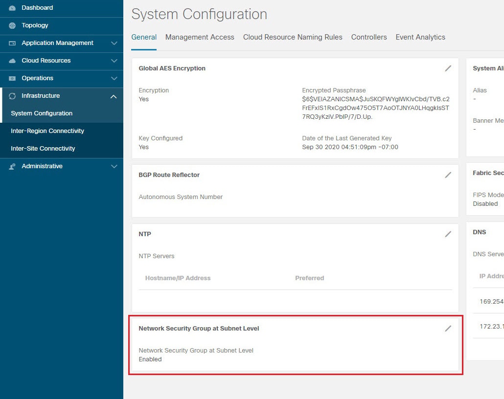
Step 5

Click Save when finished.


Creating a Certificate Authority Using the Cisco Cloud APIC GUI

This section explains how to create a certificate authority using the GUI.

Before you begin

  • Have the certificate chain.

  • If the certificate authority is for a tenant, create the tenant.

Procedure


Step 1

Click the Intent icon. The Intent menu appears.

Step 2

Click the drop-down arrow below the Intent search box and choose Administrative.

A list of Administrative options appears in the Intent menu.

Step 3

From the Administrative list in the Intent menu, click Create Certificate Authority. The Create Certificate Authority dialog box appears.

Step 4

Enter the appropriate values in each field as listed in the following Create Certificate Authority Dialog Box Fields table then continue.

Table 17. Create Certificate Authority Dialog Box Fields

Properties

Description

Name

Enter the name of the certificate authority.

Description

Enter a description of the certificate authority.

Used for

Choose from the following options:

  • Tenant—Choose if the certificate authority is for a specific tenant. When chosen, the Select Tenant option appears in the GUI.

  • System—Choose if the certificate authority is for the system.

Select Tenant

To choose a tenant:

  1. Click Select Tenant. The Select Tenant dialog box appears.

  2. From the Select Tenant dialog, click to choose a tenant in the left column then click Select. You return to the Create Certificate Authority dialog box.

Certificate Chain

Enter the certificate chain in the Certificate Chain text box.
Note 

Add the certificates for a chain in the following order:

  1. CA

  2. Sub-CA

  3. Subsub-CA

  4. Server

Step 5

Click Save when finished.


Creating a Key Ring Using the Cisco Cloud APIC GUI

This section explains how to create a key ring using the Cisco Cloud APIC GUI.

Before you begin

  • Create a certificate authority.

  • Have a certificate.

  • If the key ring is for a specific tenant, create the tenant.

Procedure


Step 1

Click the Intent icon. The Intent menu appears.

Step 2

Click the drop-down arrow below the Intent search box and choose Administrative.

A list of Administrative options appear in the Intent menu.

Step 3

From the Administrative list in the Intent menu, click Create Key Ring. The Create Key Ring dialog box appears.

Step 4

Enter the appropriate values in each field as listed in the following Create Key Ring Dialog Box Fields table then continue.

Table 18. Create Key Ring Dialog Box Fields

Properties

Description

Name

Enter the name of the key ring.

Description

Enter a description of the key ring.

Used for

  • System—The key ring is for the system.

  • Tenant—The key ring is for a specific tenant. Displays a Tenant field for specifying the tenant.

Select Tenant

To choose a tenant:

  1. Click Select Tenant. The Select Tenant dialog box appears.

  2. From the Select Tenant dialog, click to choose a tenant in the left column then click Select. You return to the Create Key Ring dialog box.

Settings

Certificate Authority

To choose a certificate authority:

  1. Click Select Certificate Authority. The Select Certificate Authority dialog appears.

  2. Click to choose a certificate authority in the column on the left.

  3. Click Select. You return to the Create Key Ring dialog box.

Private Key

Choose one of the following:

  • Generate New Key—Generates a new key.

  • Import Existing Key—Displays the Private Key text box and enables you to use an existing key.

Private Key

Enter an existing key in the Private Key text box (for the Import Existing Key option).

Modulus

Click the Modulus drop-down list to choose from the following:

  • MOD 512

  • MOD 1024

  • MOD 1536

  • MOD 2048—(Default)

Certificate

Enter the certificate information in the Certificate text box.

Step 5

Click Save when finished.


Creating a Local User Using the Cisco Cloud APIC GUI

This section explains how to create a local user using the Cisco Cloud APIC GUI.

Procedure


Step 1

Click the Intent icon. The Intent menu appears.

Step 2

Click the drop-down arrow below the Intent search box and choose Administrative.

A list of Administrative options appear in the Intent menu.

Step 3

From the Administrative list in the Intent menu, click Create Local User. The Create Local User dialog box appears.

Step 4

Enter the appropriate values in each field as listed in the following Create Local User Dialog Box Fields table then continue.

Table 19. Create Local User Dialog Box Fields

Properties

Description

Name

Enter the username of the local user.

Password

Enter the password for the local user.

Confirm Password

Reenter the password for the local user.

Description

Enter a description of the local user.

Settings

Account Status

To choose the account status:

  • Active—Activates the local user account.

  • Inactive—Deactivates the local user account.

First Name

Enter the first name of the local user.

Last Name

Enter the last name of the local user.

Email Address

Enter the email address of the local user.

Phone Number

Enter the phone number of the local user.

Security Domains

To add a security domain:

  1. Click Add Security Domain. The Add Security Domain dialog box appears.

  2. Click Select Security Domain. The Select Security Domain dialog box appears with a list of security domains in the left pane.

  3. Click to choose a security domain.

  4. Click Select to add the security domain. You return to the Add Security Domain dialog box.

  5. Add a user role:

    1. From the Add Security Domain dialog box, click Select Role. The Select Role dialog box appears with a list of roles in the left pane.

    2. Click to choose a role.

    3. Click Select to add the the role. You retun to the Add Security Domain dialog box.

    4. From the Add Security Domain dialog box, click the Privilege Type drop-down list and choose Read Privilege or Write Privilege.

    5. Click the check mark on the right side of the Privilege Type drop-down list to confirm.

    6. Click Add when finished. You return to the Create Local User dialog box where you can add another security domain.

Step 5

Click Advanced Settings and enter the appropriate values in each field as listed in the following Create Local User Dialog Box Fields: Advanced Settings table then continue.

Table 20. Create Local User Dialog Box Fields: Advanced Settings

Property

Description

Account Expires

If you choose Yes, the account is set to expire at the time that you choose.

Password Update Required

If you choose Yes, the user must change the password upon the next login.

OTP

Put a check in the box to enable the one-time password feature for the user.

User Certificates

To add a user certificate:

  1. Click Add X509 Certificate. The Add X509 Certificate dialog box appears.

  2. Enter a name in the Name field.

  3. Enter the X509 certificate in the User X509 Certificate text box.

  4. Click Add. The X509 certificate in the User X509 Certificate dialog box closes. You return to the Local User dialog box.

SSH Keys

To add a an SSH key:

  1. Click Add SSH Key. The Add SSH Key dialog box appears.

  2. Enter a name in the Name field.

  3. Enter the SSH key in the Key text box.

  4. Click Add. The Add SSH Key dialog box closes. You return to the Local User dialog box.

Step 6

Click Save when finished.


Managing Regions (Configuring a Cloud Template) Using the Cisco Cloud APIC GUI

Regions are configured during the first-time setup. When configured, you specify the regions that are managed by Cisco Cloud APIC and the region's inter-site and inter-region connectivity. This section explains how to manage regions with the cloud template using the Cisco Cloud APIC GUI after the initial installation.

For more information about cloud templates, see About the Cloud Template.

Procedure


Step 1

Click the Intent icon. The Intent menu appears.

Step 2

Click the drop-down arrow below the Intent search box and choose Configuration.

A list of options appear in the Intent menu.

Step 3

From the Configuration list in the Intent menu, click cAPIC Setup.

The Set up - Overview dialog box appears with options for DNS and NTP Servers, Region Management, and Smart Licensing.
Step 4

For Region Management, click Edit Configuration.

The Setup - Region Management dialog box appears. and the first step in the Setup - Region Management series of steps appears, Regions to Manage, with a list of managed regions.
Step 5

If you want inter-site connectivity, click to place a check mark in the Enabled box in the Inter-Site Connectivity area.

The Inter-Site Connectivity step is added in the Setup - Region Management steps at the top of the page.
Step 6

To choose a region that you want to be managed by the Cisco Cloud APIC, click to place a check mark in check box of that region.

Step 7

To deploy cloud routers locally to this region, click to place a check mark in the Cloud Routers check box for that region.

Step 8

To configure the fabric infra connectivity for the cloud site, click Next.

The next step in the Setup - Region Management series of steps appears, General Connectivity.
Step 9

To add a subnet pool for the CSRs, click Add Subnet Pool for Cloud Router and enter the subnet in the text box.

Note 

The /24 subnet provided during the Cloud APIC deployment would be sufficient for up to two cloud sites. If you need to manage more than two cloud sites, you need to add more subnets.

Step 10

Enter a value in the BGP Autonomous System Number for CSRs field.

The BGP ASN can be in the range of 1 - 65534.

Step 11

In the Assign Public IP to CSR Interface field, determine if you want to have a public or a private IP address assigned to the CSR interface.

Note that CSRs require a public IP address for intersite communication.

  • To have a public IP address assigned to the CSR interface, leave the check in the Enabled check box. By default, the Enabled check box is checked.

  • To have a private IP address assigned to the CSR interface, uncheck the Enabled check box. A private IP address is used for connectivity in this case.

Note 

Changing a CSR address from a public IP address to a private IP address (or vice-versa) is a disruptive operation and can result in traffic loss.

Beginning with release 5.1(2), both the public and private IP addresses assigned to a CSR are displayed with the other details of the router in the Cloud Resources area. If a public IP is not assigned to a CSR, only the private IP is displayed.

Step 12

To chose the number of routers per region, click the Number of Routers Per Region drop-down list and click 2, 3, 4, 6, or 8.

Step 13

Enter a username in the Username text box.

Note 

Do not use admin as a username for the Cisco Cloud Services Router when connecting to an Azure cloud site.

Step 14

Enter a password in the Password and Confirm Password text boxes.

Step 15

To choose the throughput value, click the Throughput of the routers drop-down list.

Currently, the maximum supported CSR throughput speed available for Cisco Cloud APIC is 5GB. Even though 7.5GB and 10GB options are available in the Throughput of the routers field, those throughput speeds are not supported at this time, so do not select the 7.5GB and 10GB options in the Throughput of the routers field.

Note 

Cloud routers should be undeployed from all regions before changing the throughput or login credentials.

Step 16

Enter the necessary information in the TCP MSS field, if applicable.

Beginning with Release 4.2(4q), the TCP MSS option is available to configure the TCP maximum segment size (MSS). This value will be applied to all cloud router tunnel interfaces, including VPN tunnels towards the cloud and external tunnels towards the on-premises site or other cloud sites. For VPN tunnels towards the cloud, if the cloud provider's MSS value is less than the value that you enter in this field, then the lower value is used; otherwise, the value that you enter in this field is used.

The MSS value affects only TCP traffic, and has no impact on other types of traffic, such as ping traffic.

Step 17

(Optional) To specify the license token, enter the product instance registration token in the License Token text box.

Note 

If no token is entered, the CSR will be in EVAL mode.

Note 

If you assigned private IP addresses to the CSRs in Step 11, the only supported option is Direct connect to Cisco Smart Software Manager (CSSM) when registering smart licensing for CSRs with private IP addresses (available by navigating to Administrative > Smart Licensing). You must provide reachability to the CSSM through express route in this case.

Step 18

Click Next.

  • If you placed a check mark in the Enabled box in the Inter-Site Connectivity area earlier in these procedures, Inter-Site Connectivity appears as the next step in the Setup - Region Management series of steps. Go to Step 19.

  • If you did not place a check mark in the Enabled box in the Inter-Site Connectivity area earlier in these procedures, Cloud Resource Naming Rules appears as the next step in the Setup - Region Management series of steps. Go to Step 23.

Step 19

To enter a peer public IP address of the IPsec Tunnel peer on-premises in the text box, click Add Public IP of IPSec Tunnel Peer.

Step 20

Enter the OSPF area ID in the OSPF Area Id text box.

Step 21

To add an external subnet pool, click Add External Subnet and enter a subnet pool in the text box.

Step 22

When you have configured all the connectivity options, click Next at the bottom of the page.

The Cloud Resource Naming Rules page appears.

Step 23

In the Cloud Resource Naming Rules page, configure the cloud resource naming rules, if necessary.

The cloud resource naming rules are described in detail in the Cloud Resources Naming section. If you don't need to make any changes to the naming rules, you can skip this page.

Step 24

Click Save and Continue when finished.


Configuring Smart Licensing

This task demonstrates how to set up smart licensing in the Cisco Cloud APIC.

Before you begin

You need the product instance registration token.

Procedure


Step 1

Click the Intent icon. The Intent menu appears.

Step 2

Click the drop-down arrow below the Intent search box and choose Configuration.

A list of options appear in the Intent menu.

Step 3

From the Configuration list in the Intent menu, click Set Up cAPIC. The Set up - Overview dialog box appears with options for DNS Servers, Region Management, and Smart Licensing.

Step 4

To register the Cloud APIC to Cisco's unified license management system: From Smart Licensing, click Register. The Smart Licensing dialog appears.

Step 5

Choose a transport setting:

  • Direct to connect to Cisco Smart Software Manager (CSSM)

  • Transport Gateway/Smart Software Manager Satellite

  • HTTP/HTTPS Proxy

    Note 

    An IP address is alo required when choosing HTTP/HTTPS Proxy.

Step 6

Enter the product instance registration token in the provided text box.

Step 7

Click Register when finished.


Cloud Resources Naming

Prior to Cloud APIC Release 5.0(2), the cloud resources created by the Cloud APIC in Azure were assigned names that were derived from the names of the ACI objects:

  • Resource groups were created based on the Tenant, VRF, and region. For example, CAPIC_<tenant>_<vrf>_<region>.

  • VNET names matched the name of the Cloud APIC VRF.

  • Subnet names were derived from the CIDR address space. For example, subnet-10.10.10.0_24 for the 10.10.10.0/24 cloud subnet.

  • The cloud application name was derived from the EPG name and the application profile name. For example, <epg-name>_cloudapp_<app-profile-name>

This approach is not ideal for deployments with strict cloud resource naming conventions and it does not follow the Azure best practices for naming and tagging of cloud resources.

Starting with Cloud APIC Release 5.0(2), you can create a global naming policy on the Cloud APIC, which allows you to define a custom cloud resources naming convention for all objects deployed from the Cloud APIC into the Azure cloud. You can define custom naming rules for all cloud resources during the first time setup wizard of the Cloud APIC, with the exception of the Resource group name used for the Cloud APIC ARM template deployment. The resource group name for the template is defined when you first deploy it and cannot be changed after. In addition to the global policy, you can also explicitly define the names of the cloud resources created from each Cloud APIC object using the REST API.

Starting with Cloud APIC Release 5.1(2), for Layer 4 to Layer 7 service deployments, you can provide custom names to cloud resources, such as, Network Load Balancers, Application Load Balancers and Device Application Security Groups.


Note

Keep in mind that even with custom naming policy, once a cloud resource is created, you will not be able to modify the name. If you want to change the name of an existing cloud resource, you would need to delete all configured cloud resources and recreate them. Cloud resources to be deleted include overlay-2 CIDR and subnets, Cisco Cloud Services Router 1000Vs deployed by Cloud APIC and therefore IPSec tunnels from the CSRs to every remote site.


Variables Available for Naming Rules

When creating your cloud resources naming policy, you can use the following variables to dynamically define the name of the cloud resource based on the Cisco Cloud APIC objects:

  • ${tenant} – the resource will include the name of the Tenant

  • ${ctx} – the resource will include the name of the VRF

  • ${ctxprofile} – the resources will include the cloud context profile, which is a VRF deployed in a given cloud region

  • ${subnet} – the resource will include the string subnet followed by the subnet IP address

  • ${app} – the resource will include the name of the application profile.

  • ${epg} – the resource will include the name of the EPG.

  • ${contract} – the resource will include the name of the contract

  • ${region} – the resource will include the name of the cloud region

  • ${priority} – the resource will include the name of the network security group (NSG) rule priority. This number is allocated automatically to ensure that each NSG rule name is unique

  • ${serviceType} – the resource will include an abbreviation of the service Type (only valid for private endpoint resources)

  • ${resourceName} – the resource will include the name of the target resource (only valid for private endpoint resources)

  • ${device} – the resource will include the name of the Layer 4 to Layer 7 device.

  • ${interface} – the resource will include the name of the Layer 4 to Layer 7 device interface.

  • ${deviceInterfaceDn} – the resource will include the DN of the Layer to Layer 7 device interface.

For private endpoints, the combination of the ${app}-${svcepg}-${subnet}-${serviceType}-${resourceName} makes the private endpoint name unique. Removing any of these variables might form a name of a private endpoint that already exists. This would result in a fault raised by the Cisco Cloud APIC. Also, the max length requirements vary from Azure service to service.

When you define a global naming policy using one or more of the above variables, Cisco Cloud APIC validates the string to ensure that all mandatory variables are present and no invalid string is specified.

There is a maximum name length limit in Azure. If the length of the name exceeds the length supported by the cloud provider, it rejects the config and Cisco Cloud APIC raises a fault that the resource creation failed. You can then check the fault for details and correct the naming rules. The maximum length limits at the time of Cisco Cloud APIC, Release 5.0(2) are listed below, for the latest up-to-date information and any changes to the length limit, consult the Azure documentation.

The following table provides a summary of which cloud resources support each of the naming variables above. Cells denoted with an asterisk (*) indicate variables that are mandatory for that type of cloud resource. Cells denoted with a plus sign (+) indicate that at least one of these variables is mandatory for that type of cloud resource; for example, for VNET resources you can provide ${ctx}, or ${ctxprofile}, or both.

Table 21. Supported Variables for Cloud Resources

Azure Resource

${tenant} ${ctx} ${ctxprofile} ${subnet} ${app} ${epg} ${contract} ${region} ${priority}

Resource Group

Max Length: 90

Yes*

Yes*

Yes*

Virtual Network (VNET)

Max Length: 64

Yes

Yes+

Yes+

Yes

Subnet

Max Length: 80

Yes

Yes

Yes

Yes*

Yes

Application Security Group (ASG)

Max Length: 80

Yes

Yes*

Yes*

Yes

Network Security Group (NSG)

Max Length: 80

Yes

Yes*

Yes*

Yes

Network Security Group Rule

Max Length: 80

Yes

Yes

Yes* (auto)

Table 22. Supported Variables for Cloud Resources (Layer 4 to Layer 7 device services)

Azure Resource

${tenant} ${region} ${ctxprofile} ${device} ${interface} ${deviceInterfaceDN}

Internal Network Load Balancer

Max Length: 80

Yes

Yes

Yes

Yes*

Internet-facing Network Load Balancer

Max Length: 80

Yes

Yes

Yes

Yes*

Internal Application Load Balancer

Max Length: 80

Yes

Yes

Yes

Yes*

Internet-facing Application Load Balancer

Max Length: 80

Yes

Yes

Yes

Yes*

Device ASG

Max Length: 80

Yes

Yes

Yes*

Yes*

Yes*

Naming Rules Guidelines and Limitations

When configuring custom rules for naming cloud resources, the following restrictions apply:

  • You define global naming policy during the Cloud APIC's first time setup using two sets of naming rules:

    • Hub Resource Naming Rules define names for the Hub Resource Group, Hub VNET, Overlay-1 CIDR, Overlay-2 CIDR subnet in the Infra Tenant, as well as the subnet prefixes for subnets that are created automatically by the system in the Infra tenant.

    • Cloud Resource Naming Rules define the names of the Network Security Group (NSG), Application Security Group (ASG), Network Load Balancer, Application Load Balancer, Device Application Security Group, and subnets you create in the Infra Tenant, as well as the names of all resources (Resource Groups, Virtual Networks, Subnets, NSG, ASG, Network Load Balancer, Application Load Balancer) in user Tenants.

    After you define the naming rules, you will be required to review and confirm them. Keep in mind that you must confirm the naming rules before any cloud resources are deployed.

  • Once a cloud resource is created, its name cannot be changed and the naming policy cannot be updated in the GUI. If you upgrade your Cloud APIC to Release 5.0(2) with some resources already deployed in Azure, you will also not be able to change the global custom naming rules.

    If you want to change the names of the existing cloud resources or the policy, you would need to delete the deployed resources before being able to update the global naming policy in the GUI.

    In these cases you can use the REST API to explicitly assign custom names to any new resources you create.

  • When updating cloud resources naming via REST API, we recommend you do not import configuration at the same time.

    We recommend you define any naming rules first. Then any tenant configuration.

    We recommend that you do not change the naming policy after the tenant configuration is deployed.

Viewing Cloud Resource Naming Rules

You initially define the cloud resource naming rules in the Region Management part of the first time setup wizard when you deploy your Cloud APIC, which is described in the Cisco Cloud APIC Installation Guide. After the initial setup, you can view the rules you configured in the System Configuration screen of your Cloud APIC GUI as described in this section.

Note that the information in this screen is presented in read-only view and if you want to change the rules any time after the original deployment, you will need to re-run the first time setup wizard .

Procedure


Step 1

Log in to your Cloud APIC GUI.

Step 2

Navigate to the Cloud Resource Naming Rules screen.

  1. In the Navigation sidebar, expand the Infrastructure category.

  2. From the Infrastructure category, select System Configuration.

  3. In the System Configuration screen, select the Cloud Resource Naming Rules tab.

    In the Cloud Resource Naming Rules tab, you can see a summary of the currently configured rules for the names of resources that you deploy in the cloud site from your Cloud APIC.

    If you did not configure custom naming rules before, the default rules are listed here, which use the Cloud APIC object names for cloud resources.

    If you have not accepted the naming rules you have defined during the first time setup, a warning banner will be displayed across the top of the screen.

    Note 

    Keep in mind that you must confirm the naming rules before any cloud resources are deployed.


Configuring Cisco Cloud APIC Using the REST API

Creating a Tenant Using the REST API

There are two types of subscriptions: own and shared. Each subscription type has a primary tenant. You choose the own subscription when creating a new managed or unmanaged tenant. You choose the shared subscription when creating a tenant that inherits the managed or unmanaged settings of an existing primary tenant. This section demonstrates how to create a managed and unmanaged tenant with the own type of subscription and how to create a shared subscription.

This section demonstrates how to create a tenant using the REST API using sample POST requests from the body of Postman.

Procedure


Step 1

Create an own subscription.

  1. To create an unmanaged tenant using a client secret:

        
    POST https://<cloud-apic-ip-address>/api/mo/uni.xml
    
    <fvTenant name="{{primary-tenant-name}}">
        <cloudAccount id="{{user-tenant-subscription-id}}" vendor="azure" accessType="credentials" status=""> 
            <cloudRsCredentials tDn="uni/tn-{{primary-tenant-name }}/credentials-{{ primary-tenant-name }}"/>
        </cloudAccount>
        <cloudCredentials name="{{ primary-tenant-name }}" keyId="{{application_key_id}}" key="{{client_secret_key}}">
            <cloudRsAD tDn="uni/tn-{{ primary-tenant-name }}/ad-{{active_directory_id}}"/>
        </cloudCredentials>
        <cloudAD name="{{active_directory_name}}" id="{{active_directory_id}}" />
        <fvRsCloudAccount tDn="uni/tn-{{ primary-tenant-name }}/act-[{{ user-tenant-subscription-id }}]-vendor-azure" status=""/>
    </fvTenant>
    
  2. To create a managed tenant:

       
    POST https://<cloud-apic-ip-address>/api/mo/uni.xml
    
    <fvTenant name="{{ primary-tenant-name }}">
        <cloudAccount id="{{ user-tenant-subscription-id }}" vendor="azure" accessType="managed" status="" /> 
        <fvRsCloudAccount tDn="uni/tn-{{ primary-tenant-name }}/act-[{{ user-tenant-subscription-id }}]-vendor-azure" status=""/>
    </fvTenant>
    
Step 2

Create a shared subscription:

   
POST https://<cloud-apic-ip-address>/api/mo/uni.xml

<fvTenant name="{{ primary-tenant-name }}">
    <fvRsCloudAccount tDn="uni/tn-{{ primary-tenant-name }}/act-[{{ user-tenant-subscription-id }}]-vendor-azure" status=""/>
</fvTenant>

Creating a Contract Using the REST API

This example demonstrates how to create a contract for the Cisco Cloud APIC using the REST API.

Before you begin

Create filters.

Procedure


To create a contract:

Example:


<polUni>
  <fvTenant name="t2" status="">
    <vzFilter descr="" name="http-family-destination" ownerKey="" ownerTag="">
      <vzEntry name="http" prot="tcp" etherT="ip" dFromPort="http" dToPort="http"/>
      <vzEntry name="https" prot="tcp" etherT="ip" dFromPort="https" dToPort="https"/>
    </vzFilter>
    <vzBrCP name="httpFamily">
      <vzSubj name="default" revFltPorts="yes" targetDscp="unspecified">
        <vzRsSubjFiltAtt action="permit" directives="" tnVzFilterName="http-family-destination"/>
      </vzSubj>
    </vzBrCP>
  </fvTenant>
</polUni>

Creating a Cloud Context Profile Using the REST API

This section demonstrates how to create a cloud context profile.

Before you begin

Create a VRF.

Procedure


Step 1

To create a basic cloud context profile:

Example:

<?xml version="1.0" encoding="UTF-8"?> 
<!-- api/node/mo/uni/.xml -->
<polUni>
    <fvTenant name="tn15">
    <cloudCtxProfile name="cProfilewestus151">
        <cloudRsCtxProfileToRegion tDn="uni/clouddomp/provp-azure/region-westus"/>
      <cloudRsToCtx tnFvCtxName="ctx151"/>
    <cloudCidr addr="15.151.0.0/16" primary="true" status="">
          <cloudSubnet ip="15.151.1.0/24" name="GatewaySubnet" usage="gateway">
              <cloudRsZoneAttach tDn="uni/clouddomp/provp-azure/region-westus/zone-default"/>
        </cloudSubnet>
        <cloudSubnet ip="15.151.2.0/24" name="albsubnet" >
            <cloudRsZoneAttach tDn="uni/clouddomp/provp-azure/region-westus/zone-default"/>
        </cloudSubnet>
          <cloudSubnet ip="15.151.3.0/24" name="subnet" usage="">
              <cloudRsZoneAttach tDn="uni/clouddomp/provp-azure/region-westus/zone-default"/>
        </cloudSubnet>
    </cloudCidr>
    </cloudCtxProfile>
  </fvTenant>
</polUni>
Step 2

To create a cloud context profile where you are adding a secondary VRF, CIDR, and subnet for a VNet:

Example:

<?xml version="1.0" encoding="UTF-8"?> 
<!-- api/node/mo/uni/.xml -->
<polUni>
    <fvTenant name="tenant1" status="">
        <fvCtx name="VRF1" />
        <fvCtx name="VRF2” />
        <cloudCtxProfile name="vpc1" status="">
            <cloudRsCtxProfileToRegion tDn="uni/clouddomp/provp-azure/region-centralus" status=""/>
            <cloudRsToCtx tnFvCtxName="VRF1" />
            <cloudRsCtxProfileToGatewayRouterP tDn="uni/tn-infra/gwrouterp-default" status=""/>
            <cloudCidr name="cidr1" addr="192.0.2.0/16" primary="yes" status="">
                <cloudSubnet ip="192.0.3.0/24" usage="gateway" status="">
                    <cloudRsZoneAttach status="" tDn="uni/clouddomp/provp-azure/region-centralus/zone-default"/>
                </cloudSubnet>
            </cloudCidr>
            <cloudCidr name="cidr1" addr="193.0.2.0/16" primary="no" status="">
                <cloudSubnet ip="193.0.3.0/24" usage="" status="">
                    <cloudRsSubnetToCtx tnFvCtxName="VRF2"/>
                    <cloudRsZoneAttach status="" tDn="uni/clouddomp/provp-azure/region-centralus/zone-default"/>
                </cloudSubnet>
            </cloudCidr>
        </cloudCtxProfile>
    </fvTenant>
</polUni>


Managing a Cloud Region Using the REST API

This section demonstrates how to manage a cloud region using the REST API.

Procedure


To create a cloud region:


<?xml version="1.0" encoding="UTF-8"?>
<!-- api/node/mo/uni/.xml -->
<polUni>
  <cloudDomP name="default">
       <cloudProvP vendor="azure">
          <cloudRegion adminSt="managed" name="eastus"><cloudZone name="default"/></cloudRegion>
          <cloudRegion adminSt="managed" name="eastus2"><cloudZone name="default"/></cloudRegion>
          <cloudRegion adminSt="managed" name="westus"><cloudZone name="default"/></cloudRegion>
        </cloudProvP>
    </cloudDomP>
</polUni>

Creating a Filter Using the REST API

This section demonstrates how to create a filter using the REST API.

Procedure


To create a filter:


https://<IP_Address>/api/node/mo/.xml
<?xml version="1.0" encoding="UTF-8"?>
<!-- api/node/mo/uni/.xml -->
<polUni>
    <fvTenant name="t15">
    <vzFilter name="rule1">
      <vzEntry etherT="ip" dToPort="22" prot="tcp" dFromPort="22" name="ssh"/>
      <vzEntry etherT="ip" prot="unspecified" name="any"/>
    </vzFilter>
    <vzFilter name="rule2">
      <vzEntry etherT="ip" dToPort="http" prot="tcp" dFromPort="http" name="http"/>
    </vzFilter>
    <vzFilter name="rule3">
      <vzEntry etherT="ip" dToPort="22" prot="tcp" dFromPort="22" name="ssh"/>
    </vzFilter>
    <vzFilter name='all_rule'>
        <vzEntry etherT="ip" prot="unspecified" name="any"/>
  </vzFilter>
  
    <vzBrCP name="c1">
        <vzSubj name="c1">
            <vzRsSubjFiltAtt tnVzFilterName="rule2"/>
            <vzRsSubjGraphAtt tnVnsAbsGraphName="c13_g1"/>
            <vzRsSubjFiltAtt tnVzFilterName="rule3"/>
            <vzRsSubjFiltAtt tnVzFilterName="all_rule"/>
      </vzSubj>
    </vzBrCP>
    
  </fvTenant>
</polUni>

Creating an Application Profile Using the REST API

This section demonstrates how to create an application profile using the REST API.

Before you begin

Create a tenant.

Procedure


To create an application profile:


https://<IP_Address>/api/node/mo/.xml
<?xml version="1.0" encoding="UTF-8"?> 
<!-- api/node/mo/uni/.xml -->
<polUni>
    <fvTenant name="tn15">
        <fvRsCloudAccount tDn="uni/tn-infra/act-[<subscription id>]-vendor-azure" />    
    

        <fvCtx name="ctx151"/>

        <cloudVpnGwPol name="VgwPol1"/>
        <cloudApp name="a1">

    </cloudApp>
    
  </fvTenant>
</polUni>

Configuring Network Security Groups Using the REST API

This example demonstrates how set the newer NSG-per-subnet configuration for your Cisco Cloud APIC using the REST API.

Before you begin

Review the information provided in Security Groups.

Procedure


To set the NSG-per-subnet configuration for your Cisco Cloud APIC:

Example:


<polUni>
    <cloudDomP status="">
        <cloudProvP vendor="azure">
            <cloudProvResPolCont><cloudProvSGForSubnetP enableSGForSubnet="true" status=""/></cloudProvResPolCont>
        </cloudProvP>
    </cloudDomP>
</polUni>


Creating an EPG Using the REST API

Use the procedures in this section to create an application EPG, an external EPG, or a service EPG using the REST API.

Creating a Cloud EPG Using the REST API

This example demonstrates how to create a cloud EPG using the REST API.

Before you begin

Create an application profile and a VRF.

Procedure


To create a cloud EPG:

Example:


<?xml version="1.0" encoding="UTF-8"?> 
<!-- api/node/mo/uni/.xml -->
<polUni>
    <fvTenant name="tn15">
        <fvRsCloudAccount tDn="uni/tn-infra/act-[<subscription id>]-vendor-azure" />    
    

        <fvCtx name="ctx151"/>

        <cloudVpnGwPol name="VgwPol1"/>
        <cloudApp name="a1">
    
        
        <cloudEPg name="epg1">
            <cloudRsCloudEPgCtx tnFvCtxName="ctx151"/>
            <cloudEPSelector matchExpression="custom:tag1=='value1'" name="selector-1"/>
        </cloudEPg>
    
    
    </cloudApp>
    
  </fvTenant>
</polUni>

Creating an External Cloud EPG Using the REST API

This example demonstrates how to create an external cloud EPG using the REST API.

Before you begin

Create an application profile and a VRF.

Procedure


Step 1

To create an external cloud EPG:

Example:

<?xml version="1.0" encoding="UTF-8"?> 
<!-- api/node/mo/uni/.xml -->
<polUni>
    <fvTenant name="tn15">
        <fvRsCloudAccount tDn="uni/tn-infra/act-[<subscription id>]-vendor-azure" />    
        <fvCtx name="ctx151"/>
        <cloudVpnGwPol name="VgwPol1"/>
        <cloudApp name="a1">
        <cloudExtEPg routeReachability="internet" name="extEpg-1">
            <fvRsCons tnVzBrCPName="extEpg-1"/>
            <cloudRsCloudEPgCtx tnFvCtxName="ctx151"/>
            <cloudExtEPSelector name="extSelector1" subnet="0.0.0.0/0"/>
       </cloudExtEPg>
    </cloudApp>
  </fvTenant>
</polUni>
Step 2

To create an external cloud EPG with type site-external:

Example:

<?xml version="1.0" encoding="UTF-8"?>
<!-- api/node/mo/uni/.xml -->
<polUni>
    <fvTenant name="infra">
        <cloudApp name="a1">
        <cloudExtEPg routeReachability="site-ext" name="extEpg-1">
            <fvRsCons tnVzBrCPName="extEpg-1"/>
            <cloudRsCloudEPgCtx tnFvCtxName="overlay-2"/>
            <cloudExtEPSelector name="extSelector1" subnet="10.100.0.0/16"/>
       </cloudExtEPg>
    </cloudApp>
  </fvTenant>
</polUni>

Creating a Service EPG Using the REST API

This example demonstrates how to create a service EPG using the REST API.

Before you begin

Procedure


Step 1

To create a service EPG with a deployment type of Cloud Native:

Example:


<cloudSvcEPg name="Storage" type="Azure-Storage" accessType="Private" deploymentType="CloudNative">
    <cloudPrivateLinkLabel name="ProductionSubnets"/>
    <cloudRsCloudEPgCtx tnFvCtxName="HUB-SERVICES-VRF"/>
    <cloudSvcEPSelector matchExpression="ResourceName=='StorageAcct1'" name="selector-1"/>
    <cloudSvcEPSelector matchExpression="custom:Tag=='ProdStorage'" name="selector-2"/>
</cloudSvcEPg>
Step 2

To create a service EPG with a deployment type of Cloud Native Managed:

Example:


<cloudSvcEPg name="APIM" type="Azure-ApiManagement" accessType="Private" deploymentType="CloudNativeManaged" status="">
    <cloudRsCloudEPgCtx tnFvCtxName="infra-SvcCtx" />
    <fvRsCons tnVzBrCPName="infra-APIM-Mock"/>
    <fvRsProv tnVzBrCPName="infra-managedAPIM" status=""/>
    <cloudSvcEPSelector matchExpression="IP=='10.21.52.0/28'" name="sel1" status=""/>
</cloudSvcEPg>
Step 3

To create a service EPG with a deployment type of Third-Party:

Example:


<cloudSvcEPg name="SaaS-Hub" type="Custom"  accessType="Private" deploymentType="Third-party" status="">
    <cloudRsCloudEPgCtx tnFvCtxName="infra-SvcCtx" status=""/>
    <cloudSvcEPSelector matchExpression="URL=='saassvcepg.286b0377-a9b7-40d7-a94f-67abe03ce5f4.centralus.azure.privatelinkservice'" name="s1" status=""/>
    <cloudPrivateLinkLabel name="saas-hub" status=""/>
    <fvRsProv tnVzBrCPName="SaaS-Hub" status=""/>
</cloudSvcEPg>

Creating a Cloud Template Using the REST API

This section demonstrates how to create a cloud template using the REST API. For more information about cloud templates, see About the Cloud Template.

Before you begin

Procedure


To create a cloud template:

<polUni>
  <fvTenant name="infra">
    <cloudtemplateInfraNetwork name="default" numRemoteSiteSubnetPool="2" numRoutersPerRegion="2" status="" vrfName="overlay-1">
         <cloudtemplateProfile name="default" routerPassword="cisco123" routerUsername="cisco" routerThroughput="250M" routerLicenseToken="thisismycsrtoken" />
              </cloudtemplateProfile>
      <cloudtemplateExtSubnetPool subnetpool="10.20.0.0/16"/>

      <cloudtemplateIntNetwork name="default">
        <cloudRegionName provider="azure" region="westus"/>
        <cloudRegionName provider="azure" region="westus2"/>
      </cloudtemplateIntNetwork>

      <cloudtemplateExtNetwork name="default">
        <cloudRegionName provider="azure" region="westus2"/>

        <cloudtemplateVpnNetwork name="default">

          <cloudtemplateIpSecTunnel peeraddr="23.2.1.1/32" />
          <cloudtemplateIpSecTunnel peeraddr="23.0.1.1/32" />
          <cloudtemplateIpSecTunnel peeraddr="23.1.1.1/32" />

          <cloudtemplateOspf area="0.0.0.1"/>

        </cloudtemplateVpnNetwork>

      </cloudtemplateExtNetwork>
</cloudtemplateInfraNetwork>
  </fvTenant>
</polUni>

Defining Global Cloud Resource Naming Rules or Overriding Specific Object's Name

This section provides an example REST API POST you can use to configure a global policy for naming your cloud resources or override a specific cloud resource's name.


Note

To ensure that any custom naming conventions can be supported, cloud resource names can be defined on a per-object basis. These explicit name overrides are not available in the Cloud APIC GUI and can be done using REST API only. We recommend using the global cloud resource naming policy to define the names. Explicit name overrides shouldf be used only when naming requirements cannot be met using the global naming policy.


Procedure


Step 1

To create Hub Resource Naming Rules:

<?xml version="1.0" encoding="UTF-8"?>
<!-- api/node/mo/uni/.xml -->
<polUni>
  <fvTenant name="infra">
    <cloudtemplateInfraNetwork name="default" numRemoteSiteSubnetPool="2"
    numRoutersPerRegion="2" status="" vrfName="overlay-1">
      <cloudtemplateIntNetwork name="default">
        <cloudRegionName provider="azure" region=“west’s” status="">
          <cloudtemplateRegionNameCustomization ctxProfileName="infra-vnet"
          resourceGroupName="infra-rh" subnetNamePrefix="snet-" />
        </cloudRegionName>
      </cloudtemplateIntNetwork>
    </cloudtemplateInfraNetwork>
  </fvTenant>
</polUni>
Step 2

To create Cloud Resource Naming Rules:

<?xml version="1.0" encoding="UTF-8"?>
<!-- api/node/mo/uni/.xml -->
<polUni>
  <cloudDomP name="default">
    <cloudNaming 
    azResourceGroup="${tenant}-network-${ctx}-${region}-rg" 
    azVirtualNetwork="${tenant}-${ctxprofile}-vnet" 
    azSubnet="${tenant}-${ctxprofile}-snet-${subnet}" 
    azNetworkSecurityGroup="${app}-${epg}-nsg" 
    azApplicationSecurityGroup="${app}-${epg}-asg" 
    azNetworkSecurityGroupRule="${contract}--${priority}"
    internetApplicationBalancer="agw-e-${device}"
    internalApplicationBalancer="agw-i-${device}"
    internetNetworkBalancer="lbe-${device}"
    internalNetworkBalancer="lbi-${device}"
    l4L7DeviceApplicationSecurityGroup="${deviceInterfaceDn}" 
   reviewed="yes" />
  </cloudDomP>
</polUni>
Step 3

To override an Azure cloud resource name corresponding to a specific Cloud APIC object:

You can use the same variables (for example, ${tenant}) when specifying the custom name using the API.

<?xml version="1.0" encoding="UTF-8"?>
<!-- api/node/mo/uni/.xml -->
<fvTenant name="ExampleCorp" status="">
  <fvRsCloudAccount status="" tDn="uni/tn-infra/act-[<infra-subscription>]-vendor-azure"/>
  <fvCtx name="VRF1"/>
  <cloudApp name="App1">
    <cloudEPg name="Db" azNetworkSecurityGroup="db-nsg" azApplicationSecurityGroup="db-asg-${region}">
      <cloudRsCloudEPgCtx tnFvCtxName="VRF1"/>
      <cloudEPSelector matchExpression="custom:EPG=='db'" name="100"/>
    </cloudEPg>
  </cloudApp>
  <cloudCtxProfile name="c02" azResourceGroup="custom-tc-rg1" azVirtualNetwork="vnet1">
    <cloudRsCtxProfileToRegion tDn="uni/clouddomp/provp-azure/region-westus"/>
    <cloudRsToCtx tnFvCtxName="VRF1"/>
    <cloudCidr addr="10.20.20.0/24" name="cidr1" primary="yes" status="">
      <cloudSubnet ip="10.20.20.0/24" name="subnet1" azSubnet="s1" status="">
        <cloudRsZoneAttach status="" tDn="uni/clouddomp/provp-azure/region-westus/zone-default"/>
      </cloudSubnet>
    </cloudCidr>
  </cloudCtxProfile>
</fvTenant>
Step 4

To override a Layer 4 to Layer 7 Azure cloud resource name corresponding to a specific Cloud APIC object:

You can use the same variables (for example, ${tenant}) when specifying the custom name using the API.

Override policy for load balancer:

<?xml version="1.0" encoding="UTF-8"?>
<!-- api/node/mo/uni/.xml -->
 <fvTenant>
 <cloudLB name="ALB" type="application" scheme="internet" size="small" instanceCount="2" status="" nativeLBName=”ALB” >
                <cloudRsLDevToCloudSubnet tDn="uni/tn-{{tenantName}}/ctxprofile-c1/cidr-[31.10.0.0/16]/subnet-[31.10.80.0/24]" status="" />
        </cloudLB>
 </fvTenant>

Override policy for device ASG:


<?xml version="1.0" encoding="UTF-8"?>
<!-- api/node/mo/uni/.xml --> 
 <fvTenant>
 <cloudLDev name="{{FWName}}" status="" l4L7DeviceApplicationSecurityGroup="Group1" >
            <cloudRsLDevToCtx tDn="uni/tn-{{tenantName}}/ctx-VRF1" status=""/>
            </cloudLIf>
        </cloudLDev>
 <fvTenant>