Fabric Management

Tenants

A tenant is a logical container for application policies that enable an administrator to exercise domain-based access control. A tenant represents a unit of isolation from a policy perspective, but it does not represent a private network. Tenants can represent a customer in a service provider setting, an organization or domain in an enterprise setting, or just a convenient grouping of policies.

To manage tenants, you must have either Power User or Site and Tenant Manager read-write role.

Three tenants are pre-configured for you:

  • common—A special tenant with the purpose of providing "common" services to other tenants in ACI fabrics. Global reuse is a core principle in the common tenant. Some examples of common services include shared L3Outs, DNS, DHCP, Active Directory, and shared private networks or bridge domains.

  • dcnm-default-tn—A special tenant with the purpose of providing configuration for Cisco DCNM fabrics.

  • infra—The Infrastructure tenant that is used for all internal fabric communications, such as tunnels and policy deployment. This includes switch to switch and switch to APIC communications. The infra tenant does not get exposed to the user space (tenants) and it has its own private network space and bridge domains. Fabric discovery, image management, and DHCP for fabric functions are all handled within this tenant.

When using Multi-Site Orchestrator to manage Cisco DCNM fabrics, you will use the default dcnm-default-tn that is preconfigured for you and allows you to create and manage the following objects:

  • VRFs

  • Networks

Schemas and Templates

A schema is a collection of templates, which are used for defining networking configuration, with each template assigned to a specific tenant. A template is a set of configuration objects and their properties that you deploy all at once to one or more sites. There are multiple approaches you can take when it comes to creating schema and template configurations specific to your deployment use case. The following sections describe a few simple design directions you can take when deciding how to define the schemas, templates, and policies in your Multi-Site environment.

Keep in mind that when designing schemas, you must consider the supported scalability limits for the number of schemas, templates, and objects per schema. Detailed information on verified scalability limits is available in the Cisco Multi-Site Verified Scalability Guides for your release.

Single Schema Deployment

The simplest schema design approach is a single schema deployment. You can create a single schema with all VRFs and Networks in that schema. You can then create a single application profile or multiple application profiles within the templates and deploy it to one or more sites.

This simplest approach to Multi-Site schema creation is to create all objects within the same schema and template. However, the supported number of schemas or templates per schema scalability limit may make this approach unsuitable for large scale deployments, which could exceed those limits.

Multiple Schemas Based On Object Relationships

When configuring multiple schemas with shared object references, it is important to be careful when making changes to those objects. For instance, making changes to or deleting a shared networking object can impact applications in one or more sites. Because of that, you may choose to create a template around each individual site that contains only the objects used by that site and its applications. And create different templates containing the shared objects.

For example, you can use the following templates for a configuration that you plan to deploy to 3 different sites:

  • Site 1 template

  • Site 2 template

  • Site 3 template

  • Site 1 and 2 shared template

  • Site 1 and 3 shared template

  • Site 2 and 3 shared template

  • All shared template

Similarly, rather than separating objects based on which site they are deployed to, you can also choose to create schemas and templates based on individual applications instead. This would allow you to easily identify each application profile and map them to schemas and sites as well as easily configure each application as local or stretched across sites.

However, as this could quickly exceed the templates per schema limit (listed in the Verified Scalability Guide for your release), you would have to create additional schemas to accommodate the multiple combinations. While this creates additional complexity with multiple additional schemas and templates, it provides true separation of objects based on site or application.

Template Design

In this release, we recommend creating separate templates for VRFs and Networks within each schema and then deploying the VRF templates first, followed by the templates that contain Networks. This way any VRFs required by the networks will be already created when you push Network configuration to the sites.

Similarly, when undeploying multiple networks and VRFs, we recommend undeploying the Networks template first, followed by the VRF templates. This will ensure that when VRFs are undeployed, there will be no conflicts with any existing Networks still using them.

Concurrent Configuration Updates

The Multi-Site Orchestrator GUI will ensure that any concurrent updates on the same site or schema object cannot unintentionally overwrite each other. If you attempt to make changes to a site or schema that was updated by another user since you opened it, the GUI will reject any subsequent changes you try to make and present a warning requesting you to refresh the object before making additional changes:

However, the default REST API functionality was left unchanged in order to preserve backward compatibility with existing applications. In other words, while the UI is always enabled for this protection, you must explicitly enable it for your API calls for MSO to keep track of configuration changes.


Note

When enabling this feature, note the following:

  • This release supports detection of conflicting configuration changes for Site and Schema objects only.

  • Only PUT and PATCH API calls support the version check feature.

  • If you do not explicitly enable the version check parameter in your API calls, MSO will not track any updates internally. And as a result, any configuration updates can be potentially overwritten by both subsequent API calls or GUI users.


To enable the configuration version check, you can pass the enableVersionCheck=true parameter to the API call by appending it to the end of the API endpoint you are using, for example:

https://<mso-ip-address>/mso/api/v1/schemas/<schema-id>?enableVersionCheck=true

Example

We will use a simple example of updating the display name of a template in a schema to show how to use the version check attribute with PUT or PATCH calls.

First, you would GET the schema you want to modify, which will return the current latest version of the schema in the call's response:

{
    "id": "601acfed38000070a4ee9ec0",
    "displayName": "Schema1",
    "description": "",
    "templates": [
        {
            "name": "Template1",
            "displayName": "current name",
            [...]
        }
    ],
    "_updateVersion": 12,
    "sites": [...]
}

Then you can modify the schema in one of two ways appending enableVersionCheck=true to the request URL:


Note

You must ensure that the value of the "_updateVersion" field in the payload is the same as the value you got in the original schema.


  • Using the PUT API with the entire updated schema as payload:

    PUT /v1/schemas/601acfed38000070a4ee9ec0?enableVersionCheck=true
    {
        "id": "601acfed38000070a4ee9ec0",
        "displayName": "Schema1",
        "description": "",
        "templates": [
            {
                "name": "Template1",
                "displayName": "new name",
                [...]
            }
        ],
        "_updateVersion": 12,
        "sites": [...]
    }
  • Using any of the PATCH API operations to make a specific change to one of the objects in the schema:

    PATCH /v1/schemas/601acfed38000070a4ee9ec0?enableVersionCheck=true
    [ 
        {
            "op": "replace", 
            "path": "/templates/Template1/displayName", 
            "value": "new name",
            "_updateVersion": 12
        }
    ]

When the request is made, the API will increment the current schema version by 1 (from 12 to 13) and attempt to create the new version of the schema. If the new version does not yet exist, the operation will succeed and the schema will be updated; if another API call (with enableVersionCheck enabled) or the UI have modified the schema in the meantime, the operation fails and the API call will return the following response:

{
    "code": 400,
    "message": "Update failed, object version in the DB has changed, refresh your client and retry"
}

Creating Schemas and Templates

Before you begin

  • You must have an administrative user account with full read/write privileges.

  • You must have a tenant user account with read/write tenant policy privileges.

Procedure


Step 1

Log in to your Multi-Site Orchestrator GUI.

Step 2

Create a new schema.

  1. From the left navigation pane, choose Application Management > Schemas.

  2. On the Schemas page, click Add Schema.

  3. In the schema creation dialog, provide the Name and optional description for the schema.

    By default, the new schema is empty, so you need to add one or more templates.

Step 3

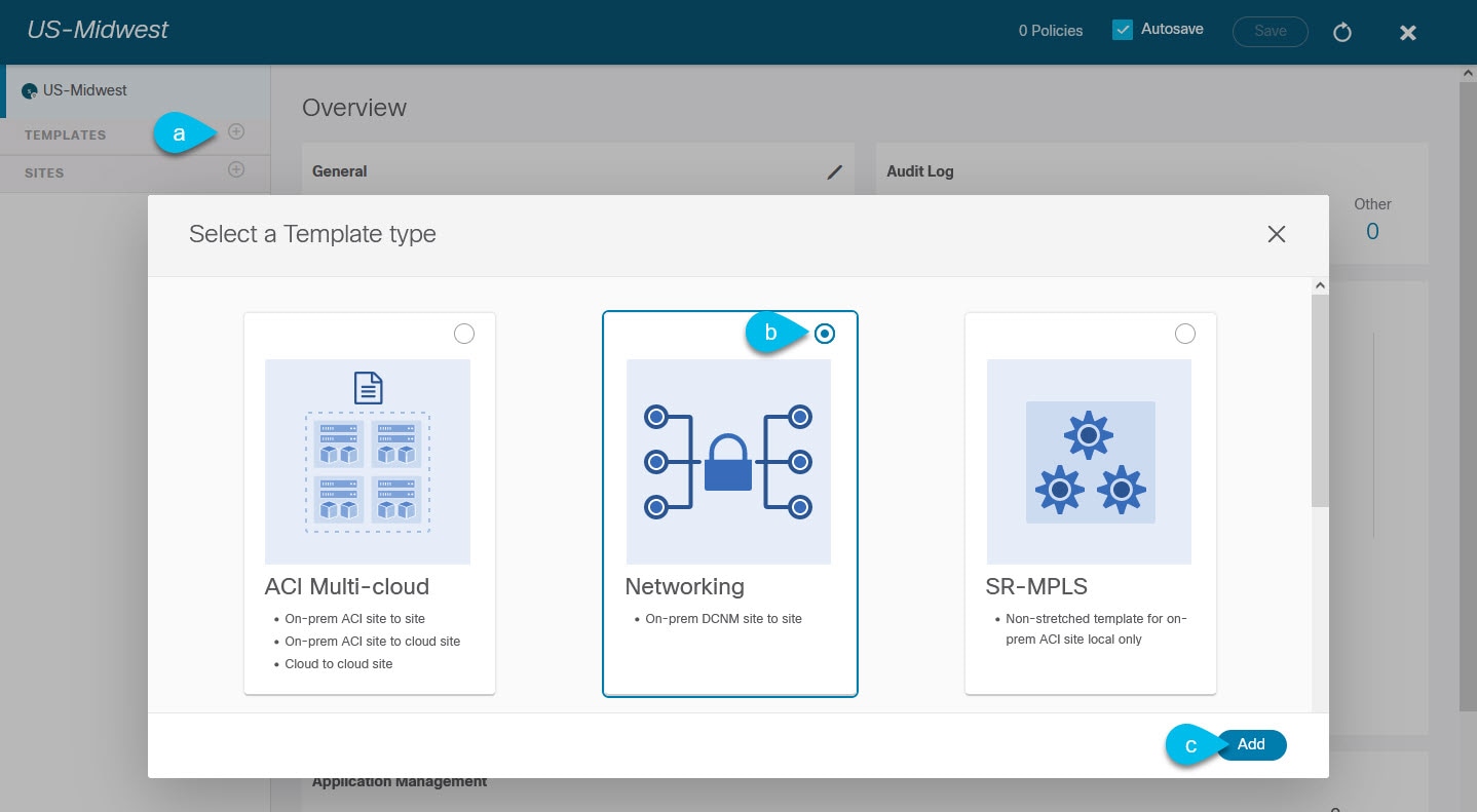
Create a template.

  1. In the left sidebar under Templates, click the + sign to add a new template.

  2. In the Select a Template type window, choose Networking for the template type.

  3. Click Add to create the template.

Step 4

Provide the name and the tenant for the template.

  1. In the right sidebar, specify the Display Name for the template.

  2. From the Select a Tenant dropdown, select the dcnm-default-tn tenant.

    Keep in mind, the user account you're using to create a new schema must be associated with the tenant you are trying to add to it, otherwise the tenant will not be available in the drop-down menu.

Step 5

Assign the templates to sites.

You deploy one template at a time, so you need to associate the template with at least one site where you want to deploy the configuration.

  1. In the left pane, click the + icon next to Sites

  2. In the Add Sites window, check the checkbox next to the sites where you want to deploy the template.

  3. From the Assign to Template dropdown next to each site, select one or more templates.

    While you deploy one template at a time to every site with which it is associated, you can associate multiple templates to a site at once.

  4. Click Save.


Importing Schema Elements From DCNM Sites

You can create new objects and push them out to one or more sites or you can import existing site-local objects and manage them using the Multi-Site Orchestrator. This section describes how to import one or more existing objects, while creating new objects is described later on in this document.

Procedure


Step 1

Open the Schema where you want to import objects.

Step 2

In the left sidebar, select the Template where you want to import objects.

Step 3

In the main pane click the Import button and select the Site from which you want to import.

Step 4

In the Import from <site-name> window that opens, select one or more objects.

Note 

The names of the objects imported into the Multi-Site Orchestrator must be unique across all sites. Importing different objects with duplicate names will cause a schema validation error and the import to fail. If you want to import objects that have the same name, you must first rename them.


Creating VRFs

This section describes how to create a VRF.

Before you begin

You must have the schema and template created and a tenant assigned to the template, as described in Creating Schemas and Templates.

Procedure


Step 1

Select the schema and template where you want to create VRF.

Step 2

In the schema edit view, choose Create Object > VRF.

Step 3

In the properties pane on the right, provide Display Name for the VRF.

Step 4

Configure the DCNM Properties for the VRF.

  1. (Optional) Provide the VRF ID.

    You can choose to specify the VNI of the VRF or leave the field empty and the VNI will be automatically allocated by the MSO from the ranges you specified in Configuring Infra: General Settings.

  2. From the VRF Profile dropdown, select the VRF profile.

    You can assign the Default_VRF_Universal profile or choose any available VRF Profile that had been previously created in DCNM. Any profiles created in DCNM are automatically imported into the MSO and are available for selection here.

  3. From the VRF Extension Profile dropdown, select the extension profile.

    You can assign the Default_VRF_Extension_Universal profile or choose any available VRF Extension Profile that had been previously created in the DCNM. Any profiles created in DCNM are automatically imported into the MSO and are available for selection here.

  4. Provide the Loopback Routing Tag.

    If a VLAN is associated with multiple subnets, then this tag is associated with the IP prefix of each subnet. Note that this routing tag is associated with overlay network creation too.

  5. Provide the Redistribute Direct Route Map.

    Specifies the route map name for redistribution of routes in the VRF.

Step 5

Configure the VRF's site-local properties.

In addition to the network's general properties that apply to every site where the VRF is deployed, you can configure site-specific properties for this VRF individually for each site.

  1. In the left sidebar under SITES, select the template where the network is defined.

  2. In the main pane, select the network.

  3. In the right Properties sidebar, provide the site-specific settings.

    You can configure the following site-local properties:

    • Enable Tenant Routed Multicast—Tenant Routed Multicast (TRM) enables multicast forwarding on the VXLAN fabric that uses a BGP-based EVPN control plane. TRM provides multi-tenancy aware multicast forwarding between senders and receivers within the same or different subnets local or across VTEPs.

      If you enable TRM, you must also provide the RP Address and Overlay Multicast Group.

    • Enable RP External if the Rendezvous Point (RP) is external to the fabric.

    • Click Add Static Leaf to select one or more leaf switches where the VRF will be configured.

      In the Add Static Leaf window that opens, choose the leaf node and provide the VLAN ID for the VRF.


Creating Networks

This section describes how to configure a DCNM network from Multi-Site Orchestrator.

Before you begin

Procedure


Step 1

Select the schema and template where you want to create the application profile.

Step 2

In the schema edit view, choose Create Object > Network.

Step 3

In the properties pane on the right, provide Display Name for the network.

Step 4

(Optional) Provide the Network ID.

You can choose to specify the network ID or leave the field empty and the ID will be automatically allocated by the MSO when you save the schema.

Step 5

Choose whether or not this is a Layer2 Only network.

Step 6

From the Virtual Routing & Forwarding dropdown, select the VRF you created for this network.

This option will be unavailable if you enabled Layer2 Only.

Step 7

From the Network Profile dropdown, select the network profile.

You can assign the Default_Network_Universal profile or choose any available Network Profile that had been previously created in DCNM. Any profiles created in DCNM are automatically imported into the MSO and are available for selection here.

Step 8

From the Network Extension Profile dropdown, select the network extension profile.

You can assign the Default_Network_Extension_Universal profile or choose any available Network Extension Profile that had been previously created in the DCNM. Any profiles created in DCNM are automatically imported into the MSO and are available for selection here.

Step 9

Provide the VLAN ID for the network.

Step 10

Provide the VLAN Name.

Step 11

Add one or more Subnets.

This option will be unavailable if you enabled Layer2 Only.

  1. Click +Add Subnet.

    An Add Subnet window opens.

  2. Click +Add Gateway IP and enter the subnet's Gateway IP address.

    You can configure up to four gateway IPs.

  3. Choose Primary for the first gateway you add.

  4. Click the checkmark to save the gateway information.

  5. Repeat the previous substeps to provide additional gateways.

  6. Click Add to finish adding the subnet.

Step 12

Choose whether you want to Suppress ARP.

Step 13

Provide the MTU for this network.

Step 14

Provide the Routing Tag.

Step 15

Configure the network's site-local properties.

In addition to the network's general properties that apply to every site where the network is deployed, you can configure site-specific properties for this network individually for each site.

  1. In the left sidebar under SITES, select the template where the VRF is defined.

  2. In the main pane, select the VRF.

  3. In the right Properties sidebar, provide the site-specific settings.

    You can configure the following site-local properties:

    • Enable Tenant Routed Multicast—Tenant Routed Multicast (TRM) enables multicast forwarding on the VXLAN fabric that uses a BGP-based EVPN control plane. TRM provides multi-tenancy aware multicast forwarding between senders and receivers within the same or different subnets local or across VTEPs.

    • Check Enable L3 Gateway Border to enable Layer 3 SVI on the border gateways to allow connecting dual-attached hosts to it.

    • Provide the DHCP Loopback ID.

      The value must be in the 0-1023 range.

    • Click +Add DHCP Server to add one or more DHCP relay servers.

      In the Add DHCP Server window that opens, provide the IP address of the DHCP relay and the VRF to which it belongs.

    • Click +Add Static Port to add one or more ports to which the network's VLAN will be attached.

      In the Add Static Port window that opens, select the leaf switch that contains the port, provide the VLAN ID, and finally click Add Port to specify one or more ports for the network.

      Note that if you want to add multiple static ports from different leaf switches, you will need to repeat the process for each leaf switch separately.


Deploying Templates

This section describes how to deploy new or updated configuration to DCNM fabrics.

Before you begin

You must have the schema, template, and any objects you want to deploy to sites already created, as described in previous sections of this document.

Procedure


Step 1

Navigate to the schema that contains one or more templates that you want to deploy.

Step 2

Assign the templates to sites.

If you have already assigned the templates to sites, skip this step.

You deploy one template at a time, so you need to associate the template with at least one site where you want to deploy the configuration.

  1. In the left pane, click the + icon next to Sites

  2. In the Add Sites window, check the checkbox next to the sites where you want to deploy the template.

  3. From the Assign to Template dropdown next to each site, select one or more templates.

    While you deploy one template at a time to every site with which it is associated, you can associate multiple templates to a site at once.

  4. Click Save.

Step 3

In the left sidebar, select the template you want to deploy.

Step 4

In the top right of the template edit view, click Deploy to sites.

The Deploy to Sites window opens that shows the summary of the objects to be deployed.

Step 5

Click Deploy to deploy the template.

  • If this is the first time you are deploying this template or you have made changes to a previously deployed template, the Deploy to Sites summary will show the configuration difference that will be deployed to sites.

    Note 

    You can filter the view using the Created, Modified, and Deleted checkboxes for informational purposes, but keep in mind that all of the changes are still deployed when you click Deploy.

  • If you have previously deployed this template but made no changes to it since, the Deploy to Sites summary will allow you to re-deploy the entire template only the Full Template option and you can simply click Deploy to re-deploy the entire template.


Schema Overview and Deployment Visualizer

When you open a schema with one or more objects defined and deployed to one or more fabrics, the schema Overview page will provide you with a summary of the deployment.

Figure 1. Schema Overview

The following details are provided on this page:

  1. General—Provides general information of the schema, such the name and description.

  2. Audit Log—Provides audit log summary of the actions performed on the schema.

  3. Sites > Health—Provides the number of sites associated with the templates in this schema sorted by the site's health status.

  4. Sites > Type—Provides the number of sites associated with the templates in this schema sorted by the site's type.

  5. Template to Site Associations > Deployment Status—Provides the number of templates in this schema that are associated with one or more sites and their deployment status.

  6. Application Management—Provides a summary of individual objects contained by the templates in this schema.

The Topology tile allows you to create a topology visualizer by selecting one or more objects to be displayed by the diagram as shown in the following figure.

Figure 2. Deployment Visualizer
  1. Configuration Options—Allows you to choose which policy objects to display in the topology diagram below.

  2. Topology Diagram—Provides visual representation of the policies configured in all of the Schema's templates that are assigned to sites.

    You can choose which objects you want to display using the Configuration Options above.

    You can also mouse over an objects to highlight all of its dependencies.