Configuring Layer 3 Interfaces

About Layer 3 Interfaces

Layer 3 interfaces forward IPv4 packets to another device using static or dynamic routing protocols. You can use Layer 3 interfaces for IP routing and inter-VLAN routing of Layer 2 traffic.

Routed Interfaces

You can configure a port as a Layer 2 interface or a Layer 3 interface. A routed interface is a physical port that can route IP traffic to another device. A routed interface is a Layer 3 interface only and does not support Layer 2 protocols, such as the Spanning Tree Protocol (STP).

All Ethernet ports are routed interfaces by default. You can change this default behavior with the CLI setup script.


Note

The default mode for the Cisco Nexus® 3550-T switch interface is Layer 3.


You can assign an IP address to the port, enable routing, and assign routing protocol characteristics to this routed interface.

You can also create a Layer 3 port channel from routed interfaces. For more information about port channels, see the Configuring Port Channels section.

Routed interfaces support exponentially decayed rate counters. Cisco NX-OS tracks the following statistics with these averaging counters:

  • Input packets/sec

  • Output packets/sec


Note

Layer 3 sub-interfaces are not supported in the Cisco Nexus® 3550-T 10.1(2t) release.


VLAN Interfaces

A VLAN interface, or switch virtual interface (SVI), is a virtual routed interface that connects a VLAN on the device to the Layer 3 router engine on the same device. Only one VLAN interface can be associated with a VLAN, but you need to configure a VLAN interface for a VLAN only when you want to route between VLANs or to provide IP host connectivity. When you enable VLAN interface creation, Cisco NX-OS creates a VLAN interface for the default VLAN (VLAN 1) to permit remote switch administration.

You must enable the VLAN network interface feature before you can see configure it. The system automatically takes a checkpoint prior to disabling the feature, and you can roll back to this checkpoint. See the Cisco Nexus® 3550-T System Management Configuration section for information on rollbacks and checkpoints.


Note

You cannot delete the VLAN interface for VLAN 1.


You can route across VLAN interfaces to provide Layer 3 inter-VLAN routing by configuring a VLAN interface for each VLAN that you want to route traffic to and assigning an IP address on the VLAN interface. For more information about IP addresses and IP routing, see the Cisco Nexus® 3550-T Unicast Routing Configuration section.

The following figure shows two hosts connected to two VLANs on a device. You can configure VLAN interfaces for each VLAN that allows Host 1 to communicate with Host 2 using IP routing between the VLANs. VLAN 1 communicates at Layer 3 over VLAN interface 1 and VLAN 10 communicates at Layer 3 over VLAN interface 10.
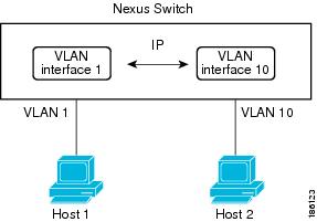
Figure 1. Connecting Two VLANs with VLAN interfaces


Note

In Cisco Nexus® 3550-T 10.1(2t) release, SVI interfaces are only supported in the default VRF instances.


Loopback Interfaces

A loopback interface is a virtual interface with a single endpoint that is always up. Any packet transmitted over a loopback interface is immediately received by this interface. Loopback interfaces emulate a physical interface. You can configure up to 1024 loopback interfaces, numbered 0 to 1023.

You can use loopback interfaces for performance analysis, testing, and local communications. Loopback interfaces can act as a termination address for routing protocol sessions. This loopback configuration allows routing protocol sessions to stay up even if some of the outbound interfaces are down.

Prerequisites for Layer 3 Interfaces

Layer 3 interfaces have the following prerequisites:

  • You are familiar with IP addressing and basic configuration. See the Cisco Nexus® 3550-T Unicast Routing Configuration section for more information about IP addressing.

Guidelines and Limitations for Layer 3 Interfaces

Layer 3 interfaces have the following configuration guidelines and limitations:

  • show commands with the internal keyword are not supported.

  • The Dynamic Host Configuration Protocol (DHCP) option is not supported in Cisco Nexus 3550-T - 10.1(2t) release.

  • Layer 3 sub-interfaces are not supported Cisco Nexus 3550-T - 10.1(2t) release.

  • SVI interfaces are only supported in Default VRF instances in Cisco Nexus 3550-T - 10.1(2t) release.

  • MTU Check is not supported in Cisco Nexus 3550-T - 10.1(2t) release and MTU CLI's do not take effect. Control-plane adjacencies would not be formed when peering devices send packets larger than 1518 bytes.

  • Cisco Nexus 3550-T - 10.1(2t) release switch does cut-through forwarding; hence there is no MTU- check implemented.

    Hardware buffering is not designed for jumbo packets and packets beyond regular MTU size 1516 is not supported.

  • There is no support for VLAN packet and byte counters in Cisco Nexus 3550-T - 10.1(2t) release.

  • Cisco Nexus 3550-T - 10.1(2t) release release does not support any byte counters on any interface. All these counters will display as 0.


Note

If you are familiar with the Cisco IOS CLI, be aware that the Cisco NX-OS commands for this feature might differ from the Cisco IOS commands that you would use.


Default Settings

The following table lists the default settings for Layer 3 interface parameters.

Table 1. Default Layer 3 Interface Parameters

Parameters

Default

Admin state

Shut

Configuring Layer 3 Interfaces

Configuring a Routed Interface

You can configure any Ethernet port as a routed interface.

Procedure

  Command or Action Purpose
Step 1

configure terminal

Example:

switch# configure terminal
switch(config)#

Enters global configuration mode.

Step 2

interface ethernet slot/port

Example:

switch(config)# interface ethernet 1/1
switch(config-if)#

Enters interface configuration mode.

Step 3

no switchport

Example:

switch(config-if)# no switchport

Configures the interface as a Layer 3 interface.

Step 4

[ip address]

Example:

switch(config-if)# ip address 192.0.2.1/8
  • Configures an IP address for this interface. See the Cisco Nexus® 3550-T Unicast Routing Configuration section for more information about IP addresses.

Step 5

show interfaces

Example:

switch(config-if)# show interfaces ethernet 1/1

(Optional) Displays the Layer 3 interface statistics.

Step 6

no shutdown

Example:

switch# 
switch(config-if)# int e1/1
switch(config-if)# no shutdown

(Optional) Clears the errors on the interfaces where policies correspond with hardware policies. This command allows policy programming to continue and the port to come up. If policies do not correspond, the errors are placed in an error-disabled policy state.

Step 7

copy running-config startup-config

Example:

switch(config)# copy running-config startup-config  

(Optional) Saves the configuration change.

Example

  • Use the medium command to set the interface medium to either point to point or broadcast.

Command

Purpose

switchport

Example:

switch(config-if)# switchport

Configures the interface as a Layer 2 interface and deletes any configuration specific to Layer 3 on this interface.

  • This example shows how to configure a routed interface:

    switch# configure terminal
    switch(config)# interface ethernet 1/1
    switch(config-if)# no switchport
    switch(config-if)# ip address 192.0.2.1/8 
    switch(config-if)# copy running-config startup-config

    The default setting for interfaces is routed. If you want to configure an interface for Layer 2, enter the switchport command. Then, if you change a Layer 2 interface to a routed interface, enter the no switchport command.

Configuring a VLAN Interface

You can create VLAN interfaces to provide inter-VLAN routing.

Procedure

  Command or Action Purpose
Step 1

configure terminal

Example:

switch# configure terminal
switch(config)#

Enters configuration mode.

Step 2

feature interface-vlan

Example:

switch(config)# feature interface-vlan

Enables VLAN interface mode.

Step 3

interface vlan number

Example:

switch(config)# interface vlan 10
switch(config-if)#

Creates a VLAN interface. The number range is from 1 to 4094.

Step 4

[ip address ip-address/length]

Example:

switch(config-if)# ip address 192.0.2.1/8
  • Configures an IP address for this VLAN interface. See the Cisco Nexus® 3550-T Unicast Routing Configuration section for more information on IP addresses.

Step 5

show interface vlan number

Example:

switch(config-if)# show interface vlan 10

(Optional) Displays the Layer 3 interface statistics.

Step 6

copy running-config startup-config

Example:

switch(config-if)# copy running-config startup-config  

(Optional) Saves the configuration change.

Example

This example shows how to create a VLAN interface:

switch# configure terminal
switch(config)# feature interface-vlan
switch(config)# interface vlan 10
switch(config-if)# ip address 192.0.2.1/8
switch(config-if)# copy running-config startup-config

Configuring a Loopback Interface

You can configure a loopback interface to create a virtual interface that is always up.

Before you begin

Ensure that the IP address of the loopback interface is unique across all routers on the network.

Procedure

  Command or Action Purpose
Step 1

configure terminal

Example:

switch# configure terminal
switch(config)#

Enters configuration mode.

Step 2

interface loopback instance

Example:

switch(config)# interface loopback 0
switch(config-if)#

Creates a loopback interface. The range is from 0 to 1023.

Step 3

[ip address ip-address/length]

Example:

switch(config-if)# ip address 192.0.2.1/8
  • Configures an IP address for this interface. See the Cisco Nexus® 3550-T Unicast Routing Configuration section for more information about IP addresses.

Step 4

show interface loopback instance

Example:

switch(config-if)# show interface loopback 0

(Optional) Displays the loopback interface statistics.

Step 5

copy running-config startup-config

Example:

switch(config-if)# copy running-config startup-config  

(Optional) Saves the configuration change.

Example

This example shows how to create a loopback interface:

switch# configure terminal
switch(config)# interface loopback 0
switch(config-if)# ip address 192.0.2.1/8
switch(config-if)# copy running-config startup-config

Configuring a DHCP Client on an Interface

You can configure the DHCP client on an SVI, a management interface, or a physical Ethernet interface for IPv4 address

Procedure

  Command or Action Purpose
Step 1

switch# configure terminal

Enters global configuration mode.

Step 2

switch(config)# interface | mgmt 0 | vlan vlan id

Selects a management interface.

Step 3

switch(config-if)# [no] [ip | ipv4] address dhcp

Requests the DHCP server for an IPv4 address.

The no form of this command removes any address that was acquired.

Step 4

switch# configure terminal

Enters global configuration mode.

Example

This example shows how to configure the IP address of a DHCP client on an SVI:

switch# configure terminal
switch(config)# interface mgmt 0
switch(config-if)# ip address dhcp

Verifying the Layer 3 Interfaces Configuration

To display the Layer 3 configuration, perform one of the following tasks:

Command

Purpose

show interface ethernet slot/port

Displays the Layer 3 interface configuration, status, and counters (including the 5-minute exponentially decayed moving average of inbound and outbound packet rates).

show interface ethernet slot/port brief

Displays the Layer 3 interface operational status.

show interface ethernet slot/port capabilities

Displays the Layer 3 interface capabilities, including port type, speed, and duplex.

show interface ethernet slot/port description

Displays the Layer 3 interface description.

show interface ethernet slot/port status

Displays the Layer 3 interface administrative status, port mode, speed, and duplex.

show interface loopback number

Displays the loopback interface configuration, status, and counters.

show interface loopback number brief

Displays the loopback interface operational status.

show interface loopback number description

Displays the loopback interface description.

show interface loopback number status

Displays the loopback interface administrative status and protocol status.

show interface vlan number

Displays the VLAN interface configuration, status, and counters.

show interface vlan number brief

Displays the VLAN interface operational status.

show interface vlan number description

Displays the VLAN interface description.

show interface vlan number status

Displays the VLAN interface administrative status and protocol status.

Monitoring the Layer 3 Interfaces

Use the following commands to display Layer 3 statistics:

Command

Purpose

load- interval {interval seconds {1 | 2 | 3}}

Cisco Nexus® 3550-T devices set three different sampling intervals to packet-rate statistics.

The range for VLAN network interface is 60 to 300 seconds, and the range for Layer interfaces is 30 to 300 seconds.

show interface ethernet slot/port counters

Displays the Layer 3 interface statistics (unicast, multicast, and broadcast).

show interface ethernet slot/port counters brief

Displays the Layer 3 interface input and output counters.

show interface ethernet errors slot/port detailed [all]

Displays the Layer 3 interface statistics. You can optionally include all 32-bit and 64-bit packet and byte counters (including errors).

show interface ethernet errors slot/port counters errors

Displays the Layer 3 interface input and output errors.

show interface ethernet errors slot/port counters snmp

Displays the Layer 3 interface counters reported by SNMP MIBs.

show interface loopback number counters

Displays the loopback interface input and output counters (unicast, multicast, and broadcast).

show interface loopback number detailed [all]

Displays the loopback interface statistics. You can optionally include all 32-bit and 64-bit packet and byte counters (including errors).

show interface loopback number counters errors

Displays the loopback interface input and output errors.

Configuration Examples for Layer 3 Interfaces

This example shows how to configure Ethernet subinterfaces:

interface ethernet 1/1.10
description Layer 3
ip address 192.0.2.1/8

This example shows how to configure a loopback interface:

interface loopback 3
ip address 192.0.2.2/32

Related Documents

Related Documents

Document Title

IP

Cisco Nexus® 3550-T Unicast Routing Configuration section

VLANs

Cisco Nexus® 3550-T Layer 2 Switching Configuration section