About ITD
Intelligent Traffic Director (ITD) is an intelligent, hardware-based, multi-terabit solution that allows you to build a scalable architecture for Layer 3 and Layer 4 traffic distribution, load balancing, and redirection.
Benefits of ITD:
-
Multi-terabit solution at line rate
-
Transparency to end device and stateless protocol benefits
-
Reduced complexities and architecture scaling for alternative features like Web Cache Communication Protocol (WCCP) and policy-based routing
-
Simplified provisioning and ease of deployment
-
Legacy service appliances can co-exist with new ones
-
Removes the requirement for an expensive external load balancer
-
No certification, integration, or qualification needed between the devices and the Cisco NX-OS switch
-
Order of magnitude OPEX savings : reduction in configuration, and ease of deployment
-
CAPEX savings : No service module or external L3/L4 load-balancer needed. Every Nexus port can be used as load-balancer
ITD features:
-
Hardware based multi-terabit/s L3/L4 load-balancing at wire-speed
-
Zero latency load-balancing
-
Redirect line-rate traffic to any devices, for example web cache engines, Web Accelerator Engines (WAE), video-caches, etc
-
Capability to create clusters of devices, for example, Firewalls, Intrusion Prevention System (IPS), or Web Application Firewall (WAF), Hadoop cluster
-
IP-stickiness
-
Resilient (like resilient ECMP), Consistent hash
-
Virtual IP based L4 load-balancing
-
Weighted load-balancing and Failaction are supported among nodes
-
Load-balances to large number of devices/servers
-
ACL along with redirection and load balancing simultaneously
-
Bi-directional flow-coherency. Traffic from A–>B and B–>A goes to same node
-
The servers/appliances don’t have to be directly connected to Nexus switch
-
Monitoring the health of servers/appliances with IP SLA-based probes
-
N + M redundancy (N number of nodes and M number of hot-standbys)
-
Automatic failure handling of servers/appliances
-
VRF support, vPC support
-
Supports both IPv4 and IPv6 (all platforms do not support IPv6)
-
The feature does not add any load to the supervisor CPU
-
Handles unlimited number of flows
-
Nondisruptive node addition or deletion
-
Simultaneous redirection and load balancing
-
Rate sharing across multiple ITD services in the same switch
Use case examples:
-
Load-balance to cluster of Firewalls.
-
Scale IPS, IDS and WAF by load-balancing to NX-OS devices
-
Scale the NFV solution by load-balancing to low cost VM/container based NFV
-
Scale the WAAS / WAE solution. Traffic redirection mechanism for the Wide Area Application Services (WAAS) or Web Accelerator Engine (WAE) solution
-
Scale the VDS-TC (video-caching) solution
-
Scale Layer-7 load-balancers, by distributing traffic to L7 LBs
-
Replaces ECMP or the port channel to avoid rehashing . ITD is resilient, and doesn’t cause re-hashing on node add/delete/failure
-
Server load balancing in DSR (Direct Server Return) mode
-
Scales up NG intrusion prevention systems (IPSs) and web application firewalls (WAFs) by load balancing to NX-OS devices
-
Load balances to Layer 5 through Layer 7 load balancers
Deployment Modes
One-Arm Deployment Mode
You can connect servers to the switch in one-arm deployment mode. In this topology, the server is not in the direct path of client or server traffic, which enables you to plug a server into the network with no changes to the existing topology or network.

Server Load-Balancing Deployment Mode
The ITD service can be configured to host a virtual IP (VIP) on the switch. Internet traffic destined for the VIP will be load balanced to the active nodes. The ITD service is not a stateful load balancer.
 Note |
You need to configure the ITD service manually and in a similar manner on each switch. |

Device Groups
Nodes can be a physical server, virtual server, or a service appliance where traffic can be load balanced. These nodes are grouped together under a device group, and this device group can be mapped to a service.
ITD supports device groups. When you configure a device group, you can specify the following:
-
The device group's nodes
-
The device group's probe
You can configure probes at the device-group level or at the node level. With node-level probing, each node can be configured with its own probe, allowing for further customization per node. Node-level probes are useful in scenarios where each node needs to be monitored differently for failure conditions.
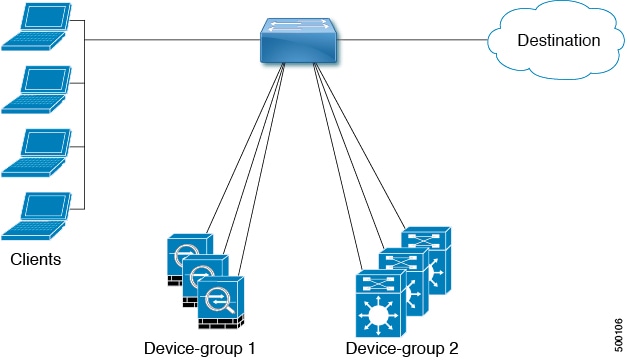
Multiple Device Groups in an ITD Service
device groups are supported in an ITD service (as shown in the figure below). An ITD service generates a single route map with different sequences that point to different device groups.
Each device group represents different types of traffic requiring different services but arriving on the same ingress interface. Traffic on the interface is redirected to the appropriate device group based on the virtual IP address. Supporting multiple device groups per ITD service on the same interface allows ITD to scale.
For a configuration example showing how to configure multiple device groups in an ITD service, see .
VRF Support
The ITD service can be configured in the default VRF as well as in non-default VRFs.
Ingress Interfaces must belong to the VRF configured for the ITD service. If no VRF is configured for the service, the ingress interface must belong to the default VRF.
Beginning Cisco NX-OS release 10.2(1), VRF may be configured for the ITD device-group. All device-group node members must be reachable in the VRF configured for the ITD device-group. If no VRF is configured for the device-group, you must ensure that all ingress interfaces for the service and node members of the associated device group are reachable in the configured VRF for service. If no VRF is configured for the device-group and the service, all ingress interfaces for the service and the node members of the associated device-group must be reachable in the default VRF.
Include and Exclude ACLs
Include ACL
The include ACL feature allows you to assign an access control list (ACL) to an ITD service. Only traffic matching the ACE is load-balanced toward the nodes and other traffic follows default routing rules.
You can configure up to 8 access-lists under one ITD service. You can associate each access list with its own device-group (Multi-ACL). When specific device-group is associated with one user ACL, that device-group takes priority and overwrites the default device-group. With this feature, ITD can load-balance traffic matching different ACLs to different device-groups.
Exclude ACL
You can configure an exclude ACL to specify the traffic that you want ITD to exclude from the ITD load balancer. The traffic, which the exclude ACL selects, is RIB-routed and bypasses ITD. An exclude ACL can filter based on both source and destination fields. The exclude ACL precedes the virtual IP address.
Virtual IP Address Filtering
A virtual IP address can be used to filter traffic for ITD. A virtual IP address and subnet mask combination for traffic filtering is supported for the destination field only.
Port Number-Based Filtering
Port numbering can be used to filter traffic for ITD. The following methods are supported to filter traffic based on Layer 4 ports (for example, port 80):
-
Matching destination ports
Any source or destination IP address with destination port 80 is matched. (For example: The virtual IP address is configured as 0.0.0.0 0.0.0.0 tcp 80.)
-
Matching source ports
Any port other than 80 bypasses ITD, and port 80 is redirected. (For example: The exclude ACL is configured as permit tcp any neq 80 any.)
-
Matching multiple port numbers
Multiple virtual IP address lines in ITD can be configured, one for each port.
Hot-Standby
The hot-standby feature reconfigures the switch to look for an operational hot-standby node and select the first available hot-standby node to replace the failed node. ITD reconfigures the switch to redirect the traffic segment that was originally headed toward the failed node to the hot-standby node. The service does not impose any fixed mapping of hot-standby nodes to active nodes.
When the failed node becomes operational again, it is reinstated as an active node. The traffic from the acting hot-standby node is redirected back to the original node, and the hot-standby node reverts to the pool of standby nodes.
When multiple nodes fail, traffic destined to all failed nodes gets redirected to the first available hot-standby node.
The hot-standby node can be configured only at the node level . At the node level, the hot-standby node receives traffic only if its associated active node fails.
ITD supports N + M redundancy where M nodes can act as hot-standby nodes for N active nodes.
Multiple Ingress Interfaces
You can configure the ITD service to apply traffic redirection policies on multiple ingress interfaces. This feature allows you to use a single ITD service to redirect traffic arriving on different interfaces to a group of nodes.
same ingress interface can be included in two ITD services, allowing one IPv4 ITD service and one IPv6 ITD service.
Including the same ingress interface in both IPv4 and IPv6 ITD services allows both IPv4 and IPv6 traffic to arrive on the same ingress interface. An IPv4 ITD policy is applied to redirect the IPv4 traffic, and an IPv6 ITD policy is applied to redirect the IPv6 traffic.
Note |
Make sure that the same ingress interface is not referenced in more than one IPv4 ITD service or more than one IPv6 ITD service. The system does not automatically enforce it and it is not supported. |
Note |
ITD IPv4 services cannot be enabled with the ingress interfaces on which IPv4 PBR policies are already applied. ITD IPv6 services cannot be enabled with the ingress interfaces on which IPv6 PBR policies are already applied. |
System Health Monitoring
ITD monitors health of the nodes and applications running on those nodes periodically to detect any failures and to handle the failure scenarios.
ICMP, TCP, UDP probes are supported.
Health of an Interface Connected to a Node
leverages the IP service level agreement (IP SLA) feature to periodically probe each node. ITD uses the Internet Control Message Protocol (ICMP) to periodically probe each node. The probes are sent at a 10-second frequency by default and can be configured down to 1 second. They are sent simultaneously to all nodes. You can configure the probe as part of the pool group configuration.
A probe is declared to have failed after retrying three times by default. At this point, the node state becomes “Failed,” and its status becomes “PROBE_FAILED.”
Node Failure Handling
Upon marking a node as down, the ITD performs the following tasks automatically to minimize traffic disruption and to redistribute the traffic to remaining operational nodes:
-
Determines if a standby node is configured to take over from the failed node.
-
If the standby node is operational, it is identified the node as a candidate node for traffic handling.
-
Redefines the standby node as active for traffic handling, if an operational standby node is available
-
Programs automatically to reassign traffic from the failed node to the newly active standby node.
Failaction Reassignment
Failaction for ITD enables traffic to the failed nodes to be reassigned to one or more active nodes. When the failed node becomes active again, it resumes serving connections. If all the nodes are down, the packets are routed automatically. All Failaction mechanisms are supported for both IPv4 and IPv6 services.
Note |
You must configure a probe under an ITD device group before enabling the failaction feature. |
Failaction Node Reassign
When a node goes down, the traffic buckets associated with the node are reassigned to the first active node found in the configured set of nodes. If the newly reassigned node also fails, traffic is reassigned to the next available active node.
When a node recovers and in the lack of any further failure events, the traffic buckets originally assigned to the node before any failures, are reassigned to it.
Failaction Node Least-Bucket
When a node goes down, the traffic buckets associated with the node are reassigned to an active node that is currently receiving traffic from the least number of traffic buckets. For each subsequent node failure, the active node with least traffic buckets is recomputed and all the buckets directed to a failed node are redirected to this node, thereby allowing the re-assigned buckets to be distributed over multiple active nodes.
When a node recovers and in the lack of any further failure events, the traffic buckets originally assigned to the node before any failures, are reassigned to it.
Failaction Bucket Distribute
When the service is enabled, ITD uses an internal algorithm to preselect varied sequences of primary nodes as alternate backup paths for with different priorities for each primary node. When a node goes down, the traffic to the node will be re-directed to the first active backup node with the highest priority, and so on, for subsequent failures, thereby minimizing the convergence delays.
When a node recovers, the traffic buckets originally assigned to this node as the primary will be reassigned to it. Any traffic buckets whose primary node is still in failure, for which the newly recovered node behaves as the highest priority active backup will also be re-assigned to it.
the primary nodes of a device-group or up to 32 primary nodes of a device-group (whichever is lesser) shall be preselected with different priorities for each node.
Note |
This algorithm is intended for relatively even traffic distribution but doesn't guarantee even distribution with node failures. |
Failaction Node-Per-Bucket
When a particular node fails, the node with least number of buckets are identified and the buckets are distributed across the other active nodes, starting from the node with least buckets.
ITD repeatedly identifies the least buckets node currently and assign one bucket to the node until all buckets are reassigned. Hence all buckets are distributed evenly among all remaining active nodes.
Note |
identifies the nodes to fail-over, based on the weights of the nodes. If a node doesn't have a weight configured a default weight of 1 is used. |
No Failaction Reassignment
When failaction node reassignment is not configured, there are two possible scenarios:
No Failaction Reassignment with a Probe Configured
The ITD probe can detect the node failure or the lack of service reachability. If the node fails, the traffic is routed and does not get reassigned, as failaction is not configured. Once the node recovers, the recovered node starts to handle the traffic.
No Failaction Reassignment without a Probe Configured
Without a probe configuration, ITD cannot detect the node failure. When the node is down, ITD does not reassign or redirect the traffic to an active node.


 Feedback