Managing the Fabric Extender Feature Set
Installing the Fabric Extender Feature Set
SUMMARY STEPS
- configure terminal
- install feature-set fex
- exit
DETAILED STEPS
| Command or Action | Purpose | |||
|---|---|---|---|---|
|
Step 1 |
configure terminal Example: |
Enters global configuration mode. |
||
|
Step 2 |
install feature-set fex Example: |
To uninstall the Fabric Extender feature set, use the no install feature-set fex command.
|
||
|
Step 3 |
exit Example: |
Exits global configuration mode. |
Uninstalling the Fabric Extender Feature Set
Ensure that you have enabled the Fabric Extender feature set.
SUMMARY STEPS
- configure terminal
- no install feature-set fex
- exit
DETAILED STEPS
| Command or Action | Purpose | |
|---|---|---|
|
Step 1 |
configure terminal Example: |
Enters global configuration mode. |
|
Step 2 |
no install feature-set fex Example: |
Uninstalls the Fabric Extender feature set. |
|
Step 3 |
exit Example: |
Exits global configuration mode. |
Enabling the Fabric Extender Feature Set
You can enable the installed Fabric Extender feature set in a VDC on the device.
SUMMARY STEPS
- configure terminal
- feature-set fex
- exit
DETAILED STEPS
| Command or Action | Purpose | |||
|---|---|---|---|---|
|
Step 1 |
configure terminal Example: |
Enters global configuration mode. |
||
|
Step 2 |
feature-set fex Example: |
Enables the Fabric Extender feature set. The feature set must be installed before it shows as an option to this command. To disable the Fabric Extender feature set, use the no feature-set fex command.
|
||
|
Step 3 |
exit Example: |
Exits global configuration mode. |
Disabling the Fabric Extender Feature Set
Ensure that you have enabled the Fabric Extender feature set.
SUMMARY STEPS
- configure terminal
- no feature-set fex
- exit
DETAILED STEPS
| Command or Action | Purpose | |
|---|---|---|
|
Step 1 |
configure terminal Example: |
Enters global configuration mode. |
|
Step 2 |
no feature-set fex Example: |
Disables the installed Fabric Extender feature set in a VDC on the device. |
|
Step 3 |
exit Example: |
Exits global configuration mode. |
Associating a Fabric Extender to a Fabric Interface
Associating a Fabric Extender to a Port Channel
Before you begin
Ensure that you have enabled the Fabric Extender feature set.
SUMMARY STEPS
- configure terminal
- interface port-channel channel
- switchport mode fex-fabric
- fex associate FEX-number
- (Optional) show interface port-channel channel fex-intf
DETAILED STEPS
| Command or Action | Purpose | |
|---|---|---|
|
Step 1 |
configure terminal Example: |
Enters global configuration mode. |
|
Step 2 |
interface port-channel channel Example: |
Specifies a port channel to configure. |
|
Step 3 |
switchport mode fex-fabric Example: |
Sets the port channel to support an external Fabric Extender. |
|
Step 4 |
fex associate FEX-number Example: |
Associates a FEX number to the Fabric Extender unit attached to the interface. The range is from 101 to 199. |
|
Step 5 |
(Optional) show interface port-channel channel fex-intf Example: |
(Optional)
Displays the association of a Fabric Extender to a port channel interface. |
Example
This example shows how to associate the Fabric Extender to a port channel interface on the parent device:
switch# configure terminal
switch(config)# interface ethernet 1/28
switch(config-if)# channel-group 4
switch(config-if)# no shutdown
switch(config-if)# exit
switch(config)# interface ethernet 1/29
switch(config-if)# channel-group 4
switch(config-if)# no shutdown
switch(config-if)# exit
switch(config)# interface ethernet 1/30
switch(config-if)# channel-group 4
switch(config-if)# no shutdown
switch(config-if)# exit
switch(config)# interface ethernet 1/31
switch(config-if)# channel-group 4
switch(config-if)# no shutdown
switch(config-if)# exit
switch(config)# interface port-channel 4
switch(config-if)# switchport
switch(config-if)# switchport mode fex-fabric
switch(config-if)# fex associate 101
 Note |
|
This example shows how to display the association of the Fabric Extender and the parent device:
switch# show interface port-channel 4 fex-intf
Fabric           FEX
Interface        Interfaces
---------------------------------------------------
Po4              Eth101/1/48   Eth101/1/47   Eth101/1/46   Eth101/1/45
                 Eth101/1/44   Eth101/1/43   Eth101/1/42   Eth101/1/41
                 Eth101/1/40   Eth101/1/39   Eth101/1/38   Eth101/1/37
                 Eth101/1/36   Eth101/1/35   Eth101/1/34   Eth101/1/33
Disassociating a Fabric Extender from an Fabric Interface
Before you begin
Ensure that you have enabled the Fabric Extender feature set.
SUMMARY STEPS
- configure terminal
- interface port-channel channel
- no fex associate <FEX-id>
- default interface ethernet <interface>
- no fex <FEX-id>
DETAILED STEPS
| Command or Action | Purpose | |
|---|---|---|
|
Step 1 |
configure terminal Example: |
Enters global configuration mode. |
|
Step 2 |
interface port-channel channel Example: |
Specifies a port channel to configure. |
|
Step 3 |
no fex associate <FEX-id> Example: |
Disassociates the Fabric Extender unit attached to the interface. |
|
Step 4 |
default interface ethernet <interface> Example: |
Sets the default settings for the member interface of the fabric port channel. |
|
Step 5 |
no fex <FEX-id> Example: |
Removes the FEX configuration. |
Configuring Fabric Extender Global Features
You can configure global features on the Fabric Extender.
Before you begin
Ensure that you have enabled the Fabric Extender feature set.
SUMMARY STEPS
- configure terminal
- fex FEX-number
- (Optional) locator-led fex FEX-number
- (Optional) description desc
- (Optional) no description
- (Optional) no type
- (Optional) serial serial
- (Optional) no serial
DETAILED STEPS
| Command or Action | Purpose | |||
|---|---|---|---|---|
|
Step 1 |
configure terminal Example: |
Enters global configuration mode. |
||
|
Step 2 |
fex FEX-number Example: |
Enters FEX configuration mode for the specified Fabric Extender. The range of the FEX-number argument is from 101 to 199.
|
||
|
Step 3 |
(Optional) locator-led fex FEX-number Example: |
(Optional)
Turns on the locator LED of a Fabric Extender. The range of the FEX-number argument is from 101 to 199. |
||
|
Step 4 |
(Optional) description desc Example: |
(Optional)
Specifies the description. The default is the string FEXxxxx where xxxx is the FEX number. If the FEX number is 123, the description is FEX0123. |
||
|
Step 5 |
(Optional) no description Example: |
(Optional)
Deletes the description. |
||
|
Step 6 |
(Optional) no type Example: |
(Optional)
Deletes the FEX type. When a Fabric Extender is connected to the fabric interfaces and does not match the configured type that is saved in the binary configuration on the parent switch, all configurations for all interfaces on the Fabric Extender are deleted. |
||
|
Step 7 |
(Optional) serial serial Example: |
(Optional)
Defines a serial number string. If this command is configured, a switch allows the corresponding chassis ID to associate (using the fex associate command) only if the Fabric Extender reports a matching serial number string.
|
||
|
Step 8 |
(Optional) no serial Example: |
(Optional)
Deletes the serial number string. |
Configuration Examples
This section contains examples of FEX configurations.
Configuring a Host Interface in a vPC Topology Connected to Two FEXs
This example shows how to configure a host vPC with a FEX (host vPC attached to two different FEXs):
| Switch 1 Configuration | Switch 2 Configuration |
|---|---|
|
|
Switch vPC Topology and Straight Through FEX Topologies (Host vPC)
The Straight through FEX is supported on the Cisco Nexus 9300-FX2 platform. Beginning with Cisco NX-OS Release 9.3(5) it is supported on the Cisco Nexus 9300-FX3 platform also.
In Cisco NX-OS Release 9.3(5), the following third-party equipment is not supported for straight-through FEX for Cisco Nexus 9300-FX3 platform switches: B22-HP, B22-IBM, B22-Dell, and B22-Fujitsu.
The following is an example of a straight through FEX topology:

Note that this topology shows:
-
The Cisco Nexus 9000 Series switch ports are directly connected to another switch or host and are configured as part of a port channel that becomes part of a vPC.
-
That vPC 20 is configured on port channel 20, which has Eth1/10 on N9k-1 and Eth2/1 on N9k-2 as members.

Note that this topology shows:
-
Each FEX is single-homed (straight-through FEX topology) with a Cisco Nexus 9000 Series switch. The host interfaces on this FEX are configured as port channels and those port channels are configured as vPCs.
-
Eth100/1/1 on N9k-1 and Eth102/1/5 on N9k-2 are configured as members of PO200 and PO200 is configured for vPC 200.
In both topologies, port channels P020 and P0200 must be configured identically on the peer switches and configuration synchronization is used to synchronize the configurations of the vPC switches.
The following table compares the sample running configuration that must be configured for the peer switches shown in the Switch vPC Topology and the FEX Straight-Through Topology (Host vPC).
|
Basic Configuration—No Port Profile |
Port Profile Configuration |
|---|---|
|
|
|
|
|
|
|
|
|
|
|
New Deployment in a vPC Topology and Straight-Through FEX Topology
In a new deployment, configuration synchronization is introduced initially to synchronize the new configuration. Because it is a new deployment, there is no existing running configuration on the FEX ports.
The following example shows how to configure the peer switches in the Switch vPC Topology and the FEX Straight-Through Topology (Host vPC):
-
Configure the CFS over IPV4 distribution to change the multicast address.
N9k-1(config)# no cfs ipv4 distribute This will prevent CFS from distributing over IPv4 network Are you sure? (y/n) [n] y N9k-2(config)# no cfs ipv4 distribute This will prevent CFS from distributing over IPv4 network. Are you sure? (y/n) [n] y -
Configure the CFSoIP multicast address on each peer switch
N9k-1(config)# cfs ipv4 mcast-address 239.255.1.1 Distribution over this IP type will be affected Change multicast address for CFS-IP? Are you sure? (y/n) [n] y N9k-2# config terminal N9k-2(config)# cfs ipv4 mcast-address 239.255.1.1 Distribution over this IP type will be affected Change multicast address for CFS-IP? Are you sure? (y/n) [n] y -
Enable CFSoIP on both switches.
N9k-1(config)# cfs ipv4 distribute N9k-2(config)# cfs ipv4 distribute -
Create a switch profile and configure the peer on both switches.
N9k-1# config sync N9k-1(config-sync)# switch-profile Test N9k-1(config-sync-sp)# sync-peers destination <out of band mgmt0 IP address of peer switch N9k-2> N9k-2# config sync N9k-2(config-sync)# switch-profile Test N9k-2(config-sync-sp)# sync-peers destination <out of band mgmt0 IP address of peer switch N9k-1> -
Add the referred global configuration to the switch profile. Because the configuration on the interfaces will be synchronized, all policies that are applied on the interface must be synchronized (for example, port profiles, QoS and ACL policies).
N9k-1(config-sync-sp)# port-profile type port-channel pc-profile N9k-1(config-sync-port-prof)# switchport mode trunk N9k-1(config-sync-port-prof)# state enabled -
Create port-channel interfaces inside the switch profile.
Note
Use switch profile mode to create the port-channel interfaces.
N9k-1(config-sync-sp)# interface port-channel 20 N9k-1(config-sync-sp)# interface port-channel 200 -
Commit the configuration in the switch profile.
N9k-1(config-sync-sp)# commit -
Add members to the port channel in configuration terminal mode on both switches. When the configuration is done in configuration terminal mode, both switches must be configured independently.
Note
In this topology, port-channel members must not be identical on the peer switches.
N9k-1(config)# interface Ethernet1/10
N9k-1(config-if)# channel-group 20 force
N9k-1(config)# interface Ethernet100/1/1
N9k-1(config-if)# channel-group 200 force

N9k-2(config)# interface Ethernet2/1
N9k-2(config-if)# channel-group 20 force
N9k-2(config)# interface Ethernet102/1/5
N9k-2(config-if)# channel-group 200 force
N9k-1(config)# interface Ethernet100/1/1 N9k-1(config-if)# switchport mode trunk N9k-1(config-if)# switchport trunk allowed vlan 1-5 N9k-2(config)# interface Ethernet2/1 N9k-2(config-if)# switchport mode trunk N9k-2(config-if)# switchport trunk allowed vlan 1-5 N9k-2(config)# interface Ethernet102/1/5 N9k-2(config-if)# switchport mode trunk N9k-2(config-if)# switchport trunk allowed vlan 1-5 -
Modify the port-channel configuration in the switch profile.
N9k-1(config-sync-sp)# interface port-channel 20 N9k-1(config-sync-sp-if)# inherit port-profile pc-profile N9k-1(config-sync-sp-if)# vpc 20 N9k-1(config-sync-sp-if)# switchport trunk allowed vlan 1-5 N9k-1(config-sync-sp)# interface port-channel 200 N9k-1(config-sync-sp-if)# inherit port-profile pc-profile N9k-1(config-sync-sp-if)# vpc 200 N9k-1(config-sync-sp-if)# switchport trunk allowed vlan 1-5 -
Commit the configuration in the switch profile.
N9k-1(config-sync-sp)# commit
Existing Deployments in a vPC Topology and Straight-Through FEX Topology
In an existing deployment, the configurations are already present and configuration synchronization is used to simplify future configuration modifications.
The following example shows how to configure the peer switches in the Switch vPC Topology and the FEX Straight-Through Topology (Host vPC):
-
Configure the CFS over IPV4 distribution to change the multicast address N9k-1(config)# no cfs ipv4 distribute This will prevent CFS from distributing over IPv4 network Are you sure? (y/n) [n] y N9k-2(config)# no cfs ipv4 distribute This will prevent CFS from distributing over IPv4 network. Are you sure? (y/n) [n] y -
Configure the CFSoIP multicast address on each peer switch N9k-1(config)# cfs ipv4 mcast-address 239.255.1.1 Distribution over this IP type will be affected Change multicast address for CFS-IP? Are you sure? (y/n) [n] y N9k-2# config terminal N9k-2(config)# cfs ipv4 mcast-address 239.255.1.1 Distribution over this IP type will be affected Change multicast address for CFS-IP? Are you sure? (y/n) [n] y -
Enable CFSoIP on both switches. N9k-1(config)# cfs ipv4 distribute N9k-2(config)# cfs ipv4 distribute -
Create a switch profile on both switches. N9k-1# config sync N9k-1(config-sync)# switch-profile Test N9k-2# config sync N9k-2(config-sync)# switch-profile Test -
Import the running configuration. N9k-1(config-sync-sp)# import running-config N9k-1(config-sync-sp-import)# show switch-profile Test bufferImport the configuration to the switch profile on both switches. You can import the configuration using one of the following three methods: -
Running configuration—All configurations that are allowed inside a switch profile are imported.
You must remove unwanted configurations. For example, you must remove port-channel member configurations.
-
Interface configuration—Only specified interface configurations are imported.
-
Manual mode—Selected configurations are imported. If the configuration that needs to be imported is small, use the manual mode to paste the desired configuration.
The following shows the command sequence to import the running configuration:
Table 2. Command Sequence to Import the Running Configuration Buffer Sequence Number
Command
1vlan 1-102 2.1 2.2 2.3interface port-channel20 switchport mode trunk vpc 20 switchport trunk allowed vlan 1-53 3.1 3.2interface port-channel100 switchport mode fex-fabric fex associate 1014 4.1 4.2 4.3Note
Switch vPC Topology
interface port-channel20 switchport mode trunk vpc 20 switchport trunk allowed vlan 1-54 4.1 4.2 4.3Note
FEX Straight-Through Topology (Host vPC)
interface port-channel200
    switchport mode trunk
    vpc 200
    switchport trunk allowed vlan 1-5
5 5.1 5.2 5.3interface Ethernet1/1 fex associate 101 switchport mode fex-fabric channel-group 1006 6.1 6.2 6.3interface Ethernet1/2 fex associate 101 switchport mode fex-fabric channel-group 1007 7.1 7.2 7.3interface Ethernet1/10 switchport mode trunk switchport trunk allowed vlan 1-5 channel-group 208 8.1 8.2 8.3interface Ethernet100/1/1 switchport mode trunk switchport trunk allowed vlan 1-5 channel-group 200
N9k-2(config-sync-sp)# import running-config -
-
(Optional) If you do not want to synchronize the fabric configuration, remove the fabric configuration and the member interfaces of PO 20 and PO 200 from the buffer. N9k-1(config-sync-sp-import)# buffer-delete 3,5,6-8The buffer-delete command deletes the unwanted configuration from the buffer.
-
Commit the configuration in the switch profile on both switches. N9k-1(config-sync-sp-import)# commit N9k-2(config-sync-sp-import)# commit -
Add the sync peer on both switches.
Note
When importing a configuration, use the sync-peers command after you import configurations on both switches independently.
N9k-1# config sync
N9k-1(config-sync)# switch-profile Test
N9k-1(config-sync-sp)# sync-peers destination <out of band mgmt0 IP address of peer switch
N9k-2>

N9k-2# config sync
N9k-2(config-sync)# switch-profile Test
N9k-2(config-sync-sp)# sync-peers destination <out of band mgmt0 IP address of peer switch
N9k-1>
N9K-1# configure sync Enter configuration commands, one per line. End with CNTL/Z. N9K-1(config-sync)# no switch-profile SP ? all-config Deletion of profile, local and peer configurations local-config Deletion of profile and local configuration profile-only Deletion of profile only and no other configuration N9396PX-1(config-sync)# no switch-profile SP
Caution
When you remove a switch profile using the no switch-profile name [all-config | local-config] command, the configuration in the switch profile is immediately removed from the running configuration. This disrupts the configurations that were present in the switch profile, such as port channel and vPC configurations.
When you remove a switch profile using the no switch-profile name [profile-only] command, the configuration in the switch profile is immediately removed from the switch profile only. This does not disrupt the configurations that were present in running config.
It is recommended to execute the CLI resync-database on both peer switches before deleting a large configuration in the switch-profile.
Perform the following action if you received the "Deletion of switch profile failed" error message when attempting to delete switch-profile: N9K-1(config-sync)# resync-database Re-synchronization of switch-profile db takes a few minutes... Re-synchronize switch-profile db completed successfully. N9K-1(config-sync)# N9K-2(config-sync)# resync-database Re-synchronization of switch-profile db takes a few minutes... Re-synchronize switch-profile db completed successfully. N9K-2(config-sync)#
Dual-Homed FEX Topology (Active-Active FEX Topology)
The dual-homed FEX (active-active) topology is supported beginning with Cisco NX-OS Release 7.0(3)I5(2) for Cisco Nexus 9300 and 9300-EX Series switches.
Beginning with Cisco NX-OS Release 9.3(5), the Dual-Homed FEX is supported on the N9K-C9336C-FX2, N9K-C93240YC-FX2, N9K-C93360YC-FX2, and N9K-C93216TC-FX2 switches. The Cisco Nexus 9300-FX2 and FX3 switches are supported on the ST and the AA FEX modes.
In Cisco NX-OS Release 9.3(5), the following third-party equipment is not supported for Dual-Homed FEX for Cisco Nexus 9300-FX2/FX3 platform switches and straight-through FEX for Cisco Nexus 9300-FX3 platform switches: B22-HP, B22-IBM, B22-Dell, and B22-Fujitsu.
The following topology shows that each FEX is dual-homed with two Cisco Nexus 9300 Series switches. The FEX-fabric interfaces for each FEX are configured as a vPC on both peer switches. The host interfaces on the FEX appear on both peer switches.
Note |
The port configuration should be the same on both switches. |
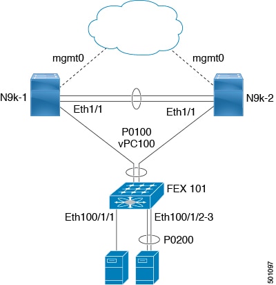
In the dual-homed FEX topology, the vPC is already operational. FEX 101 is dual-homed to both parent switches: N9k-1 and N9k-2 on FEX-fabric interfaces Ethernet 1/1.
Note |
A port channel within the same FEX is supported on Cisco Nexus 2200 Series Fabric Extenders. |
FEX 101 is configured to have two types of host interfaces. One interface is Ethernet100/1/1, which is singly attached to a server (nonport-channel member), and the other interface is Ethernet 100/1/2-3, which is configured in a port channel to the server (port-channel member).
The following table shows the sample running configuration for the peer switches. Two types of configurations are shown:
-
Basic Configuration.
-
Port profile configuration.
You can use either option or you can use both configurations together.
Note |
You can use port profiles to reduce operational overhead although they are not required. |
|
Basic Configuration—No Port Profile |
Port Profile Configuration |
|---|---|
|
|
|
|
|
|
|
|
|
|
|
|
|
|
|
|
|
New Deployments in a Dual-Homed FEX Topology
In a new deployment, configuration synchronization is introduced from the beginning to synchronize the configuration across peer switches. As a result, there is no existing running configuration on the FEX ports.
The following example shows how to configure the dual-homed FEX (active-active) topology:
-
Configure the CFS over IPV4 distribution to change the multicast address.
N9K-1(config)# no cfs ipv4 distribute This will prevent CFS from distributing over IPv4 network Are you sure? (y/n) [n] y N9K-2(config)# no cfs ipv4 distribute This will prevent CFS from distributing over IPv4 network. Are you sure? (y/n) [n] y -
Configure the CFSoIP multicast address on each peer switch.
N9K-1(config)# cfs ipv4 mcast-address 239.255.1.1 Distribution over this IP type will be affected Change multicast address for CFS-IP? Are you sure? (y/n) [n] y N9K-2# config terminal N9K-2(config)# cfs ipv4 mcast-address 239.255.1.1 Distribution over this IP type will be affected Change multicast address for CFS-IP? Are you sure? (y/n) [n] y -
Enable CFSoIP on both switches.
N9K-1(config)# cfs ipv4 distribute N9K-2(config)# cfs ipv4 distribute -
Create a switch profile on both switches.
N9K-1# config sync N9K-1(config-sync)# switch-profile Test N9K-1(config-sync-sp)# sync-peers destination /***out of band mgmt0 IP address of peer switch***/ N9K-2> N9K-2# config sync N9K-2(config-sync)# switch-profile Test N9K-2(config-sync-sp)# sync-peers destination /***out of band mgmt0 IP address of peer switch***/ N9K-1> -
Add referred global configuration to the switch profile.
Note
Because interface configurations will be synchronized, all policies that are applied on the interface must be synchronized (for example, port profiles, QoS, and ACL policies).
N9K-1(config-sync-sp)# port-profile type ethernet eth-profile N9K-1(config-sync-port-prof)# switchport mode trunk N9K-1(config-sync-port-prof)# state enabled N9K-1(config-sync-sp)# port-profile type port-channel pc-profile N9K-1(config-sync-port-prof)# switchport mode trunk N9K-1(config-sync-port-prof)# state enabled -
Configure the Ethernet interfaces (the non-port-channel members) inside the switch profile.
N9K-1(config-sync-sp)# interface Ethernet100/1/1 N9K-1(config-sync-sp-if)# inherit port-profile eth-profile N9K-1(config-sync-sp-if)# switchport trunk allowed vlan 1-10 -
Create the port-channel interface inside the switch profile.
Note
You must configure port-channel interfaces in the switch profile, not in configuration terminal mode.
This example shows that port channel 100 (vPC 100) is the EtherChannel from N9k to N2k:
N9K-1(config-sync-sp)# interface Port-channel100This example shows that port channel 200 is the EtherChannel from N2k to the end device:
N9K-1(config-sync-sp)# interface Port-channel200 -
Commit the configuration inside the switch profile.
N9K-1(config-sync-sp)# commit -
Add members to the port channel in configuration terminal mode on both switches.
Note
The configuration must be done on both switches in configuration terminal mode.
This example shows that N9k-1- Ethernet1/1 is a FEX-fabric member of port channel 100:
N9K-1(config)# int ether1/1
N9K-1(config-if)# channel-group 100 force
This example shows that N9K-1- Ethernet1/100/2-3 are members of port channel 200:
N9K-1(config)# interface Ethernet100/1/2-3
N9K-1(config-if-range)# channel-group 200 force
This example shows that N9K-2- Ethernet1/1 is a FEX-fabric interface that is in port channel 100:
N9K-2(config)# int ether1/1
N9K-2(config-if)# channel-group 100 force
This example shows that N9K-2- Ethernet1/100/2-3 are members of port channel 200:
N9K-2(config)# interface Ethernet100/1/2-3
N9K-2(config-if-range)# channel-group 200 force
N9K-1(config)# interface Ethernet100/1/2-3 N9K-1(config-if-range)# switchport mode trunk N9K-1(config-if-range)# switchport trunk allowed vlan 1-5 N9K-2(config)# interface Ethernet100/1/2-3 N9K-2(config-if-range)# switchport mode trunk N9K-2(config-if-range)# switchport trunk allowed vlan 1-5 -
Modify the port-channel configuration in the switch profile.
N9K-1(config-sync-sp-if)# interface Port-Channel100 N9K-1(config-sync-sp-if)# switchport mode fex-fabric N9K-1(config-sync-sp-if)# fex associate 101 N9K-1(config-sync-sp-if)# vpc 100 N9K-1(config-sync-sp)# interface Port-channel200 N9K-1(config-sync-sp-if)# inherit port-profile pc-profile N9K-1(config-sync-sp-if)# switchport trunk allowed vlan 1-5 -
Commit the configuration in the switch profile.
N9K-1(config-sync-sp)# commit
Existing Deployment with a Dual-Homed FEX Topology
In an existing deployment, the configurations are already present and configuration synchronization is used to simplify future configuration modifications.
The following example shows how to configure the peer switches in the vPC topology for the dual-homed FEX (active-active) topology:
-
Configure the CFS over IPV4 distribution to change the multicast address. N9K-1(config)# no cfs ipv4 distribute This will prevent CFS from distributing over IPv4 network Are you sure? (y/n) [n] y N9K-2(config)# no cfs ipv4 distribute This will prevent CFS from distributing over IPv4 network. Are you sure? (y/n) [n] y -
Configure the CFSoIP multicast address on each peer switch. N9K-1(config)# cfs ipv4 mcast-address 239.255.1.1 Distribution over this IP type will be affected Change multicast address for CFS-IP? Are you sure? (y/n) [n] y N9K-2# config terminal N9K-2(config)# cfs ipv4 mcast-address 239.255.1.1 Distribution over this IP type will be affected Change multicast address for CFS-IP? Are you sure? (y/n) [n] y -
Enable CFSoIP on both switches. N9K-1(config)# cfs ipv4 distribute N9K-2(config)# cfs ipv4 distribute -
Create a switch profile on both switches. N9K-1# config sync N9K-1(config-sync)# switch-profile Test N9K-2# config sync N9K-2(config-sync)# switch-profile Test -
Commit the configuration in the switch profile on both switches. N9K-1(config-sync-sp)# commit N9K-2(config-sync-sp)# commit -
Import the running configuration. N9K-1(config-sync-sp)# import running-config N9K-1(config-sync-sp-import)# show switch-profile Test bufferImport the configuration to the switch profile on both switches. You can import the configuration using one of the following three methods:
-
Running configuration—All configurations that are allowed inside a switch profile are imported.
You must remove unwanted configurations. For example, you must remove port-channel member configurations if the member interfaces do not match on the peer switches.
-
Interface configuration—Only specified interface configurations are imported.
-
Manual mode—Selected configurations are imported. If the configuration that needs to be imported is small, use the manual mode to paste the desired configuration.
The following shows the command sequence to import the running configuration:
Table 4. Command Sequence to Import the Running Configuration Buffer Sequence Number
Command
1vlan 1-102 2.1 2.2 2.3interface port-channel100 switchport mode fex-fabric vpc 100 fex associate 1013 3.1 3.2interface port-channel200 switchport mode trunk switchport trunk allowed vlan 1-54 4.1 4.2 4.3interface Ethernet1/1 fex associate 101 switchport mode fex-fabric channel-group 1005 5.1 5.2 5.3interface Ethernet100/1/1 switchport mode trunk switchport trunk allowed vlan 1-106 6.1 6.2 6.3interface Ethernet100/1/2 switchport mode trunk switchport trunk allowed vlan 1-5 channel-group 2007 7.1 7.2 7.3interface Ethernet100/1/3 switchport mode trunk switchport trunk allowed vlan 1-5 channel-group 200
-
-
Remove member interfaces of PO 100 and PO 200 from the buffer. N9K-1(config-sync-sp-import)# buffer-delete 4, 6, 7Use the buffer-delete command to delete the unwanted configuration from the buffer.
-
Commit the configuration in the switch profile on both switches. N9K-1(config-sync-sp-import)# commit N9K-2(config-sync-sp-import)# commit -
Add the sync peer on both switches. Note
When importing the configuration, you must use the sync-peers command after the configurations are imported independently on both switches.
N9K-1# config sync
N9K-1(config-sync)# switch-profile sp
N9K-1(config-sync-sp)# sync-peers destination /***out of band mgmt0 IP address of peer switch***/
N9K-2>

N9K-2# config sync
N9K-2(config-sync)# switch-profile sp
N9K-2(config-sync-sp)# sync-peers destination /***out of band mgmt0 IP address of peer switch***/
N9K-1>
N9K-1# configure sync Enter configuration commands, one per line. End with CNTL/Z. N9K-1(config-sync)# no switch-profile SP ? all-config Deletion of profile, local and peer configurations local-config Deletion of profile and local configuration profile-only Deletion of profile only and no other configuration N9396PX-1(config-sync)# no switch-profile SPCaution
When you remove a switch profile using the no switch-profile name [all-config | local-config] command, the configuration in the switch profile is immediately removed from the running configuration. This disrupts the configurations that were present in the switch profile, such as port channel and vPC configurations.
When you remove a switch profile using the no switch-profile name [profile-only] command, the configuration in the switch profile is immediately removed from the switch profile only. This does not disrupt the configurations that were present in running config.
It is recommended to execute the CLI resync-database on both peer switches before deleting a large configuration in the switch-profile.
Perform the following action if you received the "Deletion of switch profile failed" error message when attempting to delete switch-profile: N9K-1(config-sync)# resync-database Re-synchronization of switch-profile db takes a few minutes... Re-synchronize switch-profile db completed successfully. N9K-1(config-sync)# N9K-2(config-sync)# resync-database Re-synchronization of switch-profile db takes a few minutes... Re-synchronize switch-profile db completed successfully. N9K-2(config-sync)#
 Feedback