Configuring Service Chaining with Security Groups

Information About ePBR and Group Policy Option

Beginning with Cisco NX-OS Release 10.5(1)F, users can redirect traffic flows between endpoints part of different Security-Groups. The redirection can happen through a single service function (as a firewall or a load-balancer) or through a chain of service functions. Beginning with Cisco NX-OS Release 10.5(2)F, users can include up to 5 service functions in a service chain. A given service function is built with one or more endpoints, representing the service devices performing such function. Traffic flows can be load-balanced across these service endpoints, while ensuring that both directions of traffic flow symmetrically use the same service endpoint. The onboarding of these service-devices, health monitoring mechanisms, and the user intent of chaining and load-balancing the traffic based on the properties of these service devices is captured and enforced through ePBR. To know more about micro-segmentation configuration, See Micro-segmentation for VXLAN Fabrics Using Group Policy Option (GPO).

ePBR Service and Service-chain

You must first create a service function, which is defined with one or more endpoints with their specific attributes. Service endpoints are the service appliances such as firewall, IPS, and so on, that are available in the network to which traffic needs to be redirected. You can also define probes to monitor the health of the service endpoints. ePBR also supports load balancing along with service-chaining. ePBR allows you to configure multiple service endpoints as a part of a specific service function and would load-balance traffic among these endpoints, always ensuring that the two legs of the same traffic flow are using the same service endpoint. This is required when the different service endpoints defined for a given service function are not clustered and hence do not share connection states between them.

You must specify the VRF context for the service as the context in which the service endpoints are reachable.

After creating one (or more) ePBR services, you must create an ePBR service-chain. The ePBR service-chain allows you to define the service function (or the chain of service functions) through which traffic should be redirected along with the order in which this needs to be done.

Services used in a chain are identified by a sequence number. In NXOS 10.5(1)F, only a single service function may be specified inside a service-chain, thereby supporting only redirection and load-balancing capabilities to a single service functions before traffic is permitted to its destination.

In every service sequence, you can define the fail-action method such as drop, forward, and bypass indicating the action that needs to be taken in the event of failures of all endpoints in the service. If no fail-action is configured, the default behavior is to drop the traffic when the service is considered as failed.

The ePBR service-chain also allows you to specify the manner in which traffic needs to be load-balanced amongst the endpoints inside a service.

Beginning with Cisco NX-OS Release 10.5(2)F, ePBR multi-node service-chains are supported with Group Policy Options. A maximum of 5 service functions (nodes) can be configured in a service chain. Multi node service chain can contain firewall, load balancer, NAT, IPS and other devices.

Beginning with Cisco NX-OS Release 10.5(2)F, sources and destinations for the contracts using ePBR single node or multi node service-chains may be distributed across multiple sites using VXLAN Group Policy Options.

Beginning with Cisco NX-OS Release 10.5(2)F,ePBR multi-node service-chains and multi-site features are supported with sources and destinations in different VRF contexts. Service devices can belong to source VRF, destination VRF, or any other VRF.
Security Group for Service

You must configure security-group identifiers, as services can also be deployed in one arm mode of ePBR services in order to use the service for VxLAN GPO based redirection and chaining. This configuration is required to correctly steer the traffic to the service devices and through the chain.

These security-groups must be defined in the system as selector of type layer4-7. Each of the connected interfaces for the service endpoints inside the service must be mapped to the correct security-group as match interface selectors. For more details, see Creating a Security Group on Micro-segmentation for VXLAN Fabrics Using Group Policy Option (GPO).

Connected interfaces for all the forward arms of the service endpoints must be mapped to the same identifier that is specified as the forward security-group for the ePBR service.

Connected interfaces for all the reverse arms of the service endpoints must be mapped to the same identifier that is specified as the reverse security-group for the ePBR service.

Only one security-group identifier should be configured for ePBR services with one-arm endpoints.

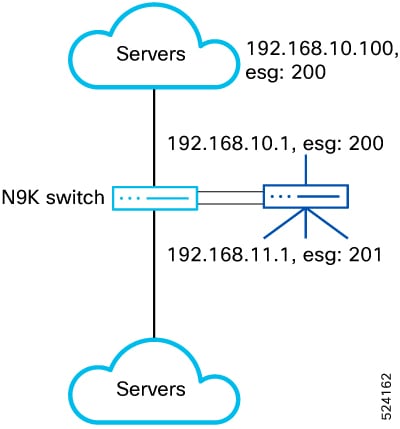
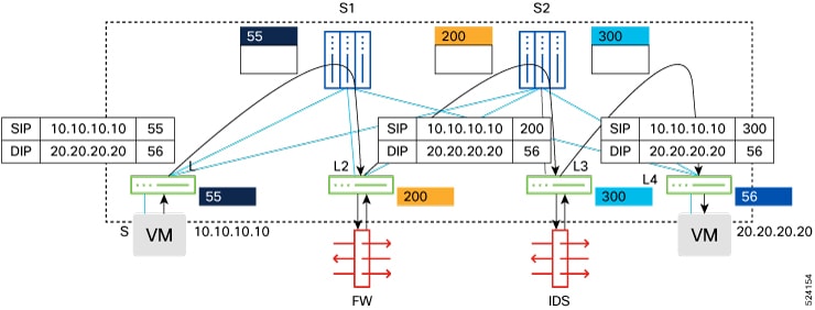
Two unique forward and reverse security-group identifiers should be configured for ePBR services with dual-arm endpoints. See figure 1 for a topology that explains the micro-segmentation based redirection and chaining.

Figure 1. Micro-segmentation with Service Chaining

Using ePBR Service-chains with SGACL Policies and Contracts

ePBR service-chain with GPO can provide traffic redirection using GPO policies and contracts. Service-chain can be enabled for security contracts by attaching it to match class-maps inside policies used by contracts. For more details about the configuration, see Micro-segmentation for VXLAN Fabrics Using Group Policy Option (GPO).

ePBR Health Monitoring and Fail-action

ePBR monitors the health of the endpoints by provisioning IP SLA probes and object tracks to track the IP SLA reachability when you apply the probe configuration.

ePBR supports various probes for protocols such as ICMP, TCP, UDP, DNS, and HTTP. ePBR also supports user defined tracks, which allows you to create tracks with various parameters including millisecond probes and associate them with ePBR endpoints.

You can configure ePBR probe options for a service if all the endpoints of the service require similar probing methods and protocols. If one or more endpoints require a different probing mechanism, you can configure probe options specific to those forward and reverse endpoints. You can also configure frequency, timeout, retry up and down counts. For service-endpoints distributed in a VXLAN environment, users must configure source loopback interfaces for the endpoints or service probes. The IP Addresses of these loopback interfaces are used as the unique source IP for the IP SLA sessions established with these endpoints.

When probes are configured for the service, forward and reverse arms do not need to have a unique loopback. They can share the same loopback or a different loopback can be provided.

You can define tracks separately and assign the track ID to the forward and reverse arm of each service-endpoint in ePBR. These track IDs should not be re-used across different endpoints in the same or different ePBR service but may be shared between the forward and reverse arms of the endpoint. If you do not assign any user-defined track to an endpoint, ePBR will create a track using the probe method for the endpoint. If no probe method is defined at the endpoint level, the probe method configured for the service level will be used.

In events of device failures, traffic that was redirecting to the failed devices will redirect to other reachable devices, until the service is detected as failed. Resilient hashing is supported during device failures for a service function deployed with multiple service endpoints. Traffic that was always being redirected to a specific service endpoint continues to redirect to the same device in events of failures of other service endpoints part of the same service fucntion.

ePBR supports the following fail-action mechanisms for its service chain sequences:

  • Drop

  • Forward

  • Bypass

Drop indicates that the traffic must be dropped when the service in the current sequence is considered as failed. This is the default behavior when no fail-action is configured.

Forward indicates that upon failure of the service in the current sequence, traffic should use the regular routing.  This fail-action mechanism is only supported when a single service function is defined in the chain.

Bypass indicates that the traffic must be redirected to the next service function in the chain when the service in the current sequence is considered as failed. For a service-chain with a single sequence, when using bypass traffic would use regular routing like the fail-action option of forward.

Load-Balancing Methods for Service Functions

Beginning with Cisco NX-OS 10.5(1)F, ePBR with GPO supports load-balancing traffic between service endpoints that are part of the same service function. Load-balance method may be configured for a service-chain if the same load-balance mechanism is desired for every service function in the chain. If one or more service functions or sequences inside the chain require a different load-balancing mechanism, this may be configured for the specific sequence inside the chain. Traffic may be load-balanced using source IP parameters, destination-IP parameters or source IP, destination IP along with the protocol indications available in the IP headers. ePBR with micro-segmentation ensures traffic is symmetrically load-balanced to the same service device in both directions.

Weighted Load-balancing

Beginning with Cisco NX-OS 10.5(1)F, ePBR with GPO supports load-balancing traffic to service endpoints proportional to the configured weights of the endpoints.

Each service endpoint configured inside a service-function can have a weight configuration. The weight range is 1-10. The total number of weights per service function is up to 128. The service-endpoints can be optionally configured based on the bandwidth or capacity of the device. If a service function is not configured with weights, all the service-endpoints configured inside the service function are considered to have a weight of 1, and the traffic is load-balanced through equal-cost multipath mechanism.

During endpoint failures, endpoints with higher weights will be preferred over endpoints with lower weights to receive the traffic of the failed endpoints.

Note that the weighted traffic distribution to the service devices is still dependent on the choice of the load-balancing algorithm and the distribution of the source and/or destination IP addresses of the traffic flows being received for service-chaining by the Nexus 9000 switch. See figure 2 for a weighted load-balancing arrangement.

Figure 2. Weighted Load-balancing

N+M Redundancy 

Beginning with Cisco NX-OS 10.5(1)F, ePBR with GPO supports the ability to define service endpoints in hot-standby mode. M hot-standby service endpoints may be defined for a service function, with N primary (active) endpoints. When all primary service endpoints are available, no traffic is redirected to the hot-standby service endpoints.

On failure of an active service endpoint inside an ePBR service function with hot-standby endpoints, traffic that was load-balanced to the failed service endpoint, is now redirected to an available hot-standby service endpoint.

On subsequent failures of more active endpoints and after all hot-standby endpoints have been utilized as backups for active endpoints, traffic that was handled by newly failed active endpoints may start being redirected to one or more available active and hot-standby endpoints.

When the active endpoint recovers, traffic that was being redirected to it, prior to its failure, will be restored to it.  This behavior is unavoidable, and the traffic sessions may be required to get reestablished through the restored, stateful service endpoint.

Hot-standby endpoints may be configured with weights. On failure of a weighted active endpoint inside an ePBR service function with weighted hot-standby endpoints, traffic is first redirected to a weighted hot-standby endpoint with equal or higher weight than the failed active endpoint.  See figure 3 for a N+M redundancy arrangement.

Figure 3. N+M Redundancy

Redirection to NAT Devices

Beginning with Cisco NX-OS 10.5(1)F, ePBR with GPO supports redirection of traffic to service devices that modify the destination and/or source IP addresses of the traffic. These devices may be external load-balancers, NATTing firewalls and CGNAT devices.  

Service devices may perform only destination NAT (load-balancers with SNAT disabled), only source NAT (CGNAT devices for return traffic) or both (load-balancers with SNAT enabled).  

Traffic to devices such as external load-balancers performing destination NAT in the forward direction do not need policy-based redirection but need to be permitted in order to reach the VIP address exposed by the load-balancer.  

Similarly, traffic in the reverse direction returning to devices such as external load-balancers or CGNAT devices, that have performed Source NAT in the forward direction, do not need policy-based redirection, but need to be permitted.  

Traffic to devices such as external load-balancers that do not have source NAT enabled, require policy-based redirection for traffic in the reverse direction. 

As described above, traffic to these services needs to be handled in different ways based on their NAT capabilities. Additionally, due to the modification of the IP addresses of the traffic by these appliances, the destination and/or source security-group tags may be different before and after redirection to these services.  Handling these variances may ordinarily require complex asymmetric, uni-directional contracts. 

ePBR simplifies the contract creation for the user by allowing the user to indicate that the service function in the ePBR service-chain at a particular sequence, has destination and/or source NAT capabilities. This is done by configuring an action for the service inside the chain, for the forward and reverse directions of traffic.

  • Services that only perform destination NAT on the traffic only are configured with action of route for the forward direction.

  • Services that only perform both destination and source NAT on the traffic, are configured with action of route for both directions of traffic.

  • Services that perform only source NAT on the traffic are configured with action of route only for the reverse direction of traffic.

The configuration options of route allow users to create a single contract from consumer to provider ESGs. This configuration reduces the burden of creating separate contracts between consumer to load- balancer then from load-balancer to the provider ESG due to the change in destination ESG.

When no action is configured for any direction, the service functions inside the chain are treated as requiring redirection in both directions. Fail-action and threshold features will not be supported for service functions in the service-chain that have action of route configured for either the forward or reverse directions.

Figure 4. 2-arm Load-balancer (without SNAT) Service Device Insertion

ePBR and GPO Multi-Site

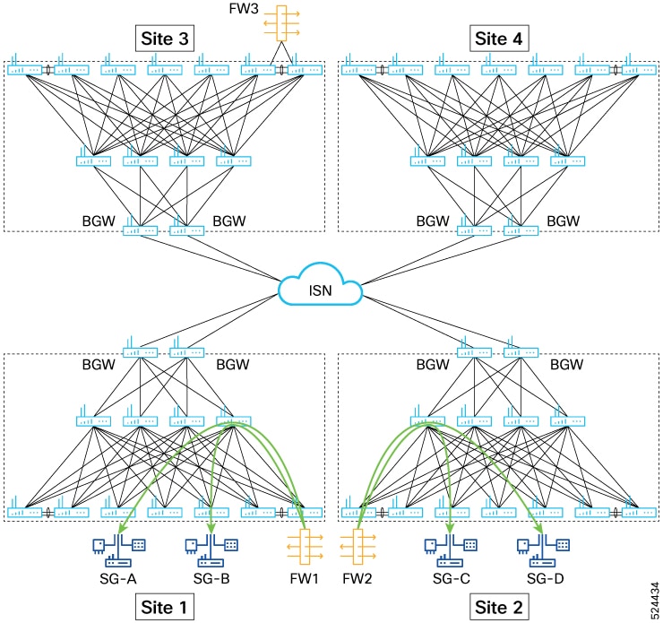
Beginning with Cisco NX-OS Release 10.5(2)F, traffic flows between endpoints of different security-groups belonging to multiple sites may be redirected to a service-chain by enabling multi-site mode for the service-chain. These single node or multi-node service-chains may consist of service functions such as firewall, load balancer, NAT, IPS, TCP optimizer and so on. Using this feature, users can interconnect and manage Security Group with service-chaining across different NX-OS VXLAN EVPN fabrics, whether those are physically collocated or geographically dispersed.

Figure 5. Local Site Local Site Security Groups with Local Service Chain

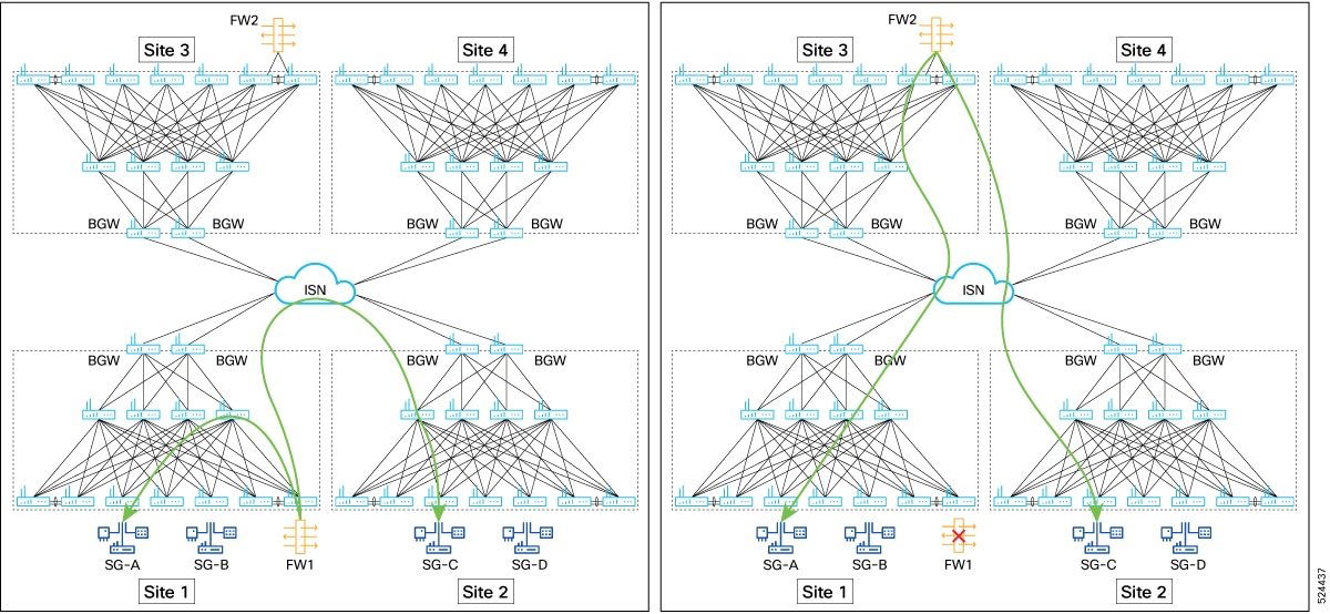
Sites 1 and 2 have their own service functions, and service chains are created between SG-A and SG-B, and SG-C and SG-D using the service functions FW 1 and FW 2 respectively within the same site. The failover service chain for site 1 can be created using FW2 from site 2, and for site 2 using FW1 from site 1.

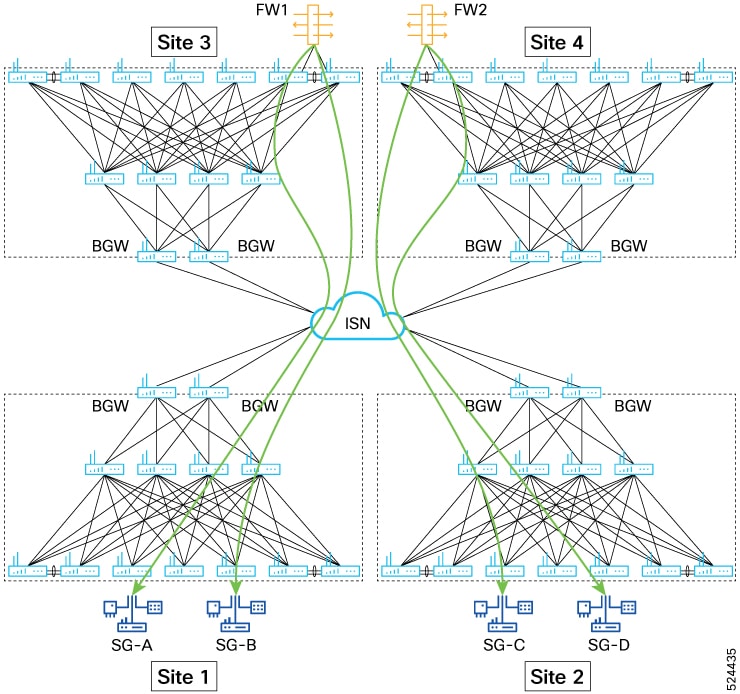
Figure 6. Local Site Security Groups with No Local Service Chain

If there are no service functions available within the same site, users can use service functions available in the remote sites to create service chain using contract.

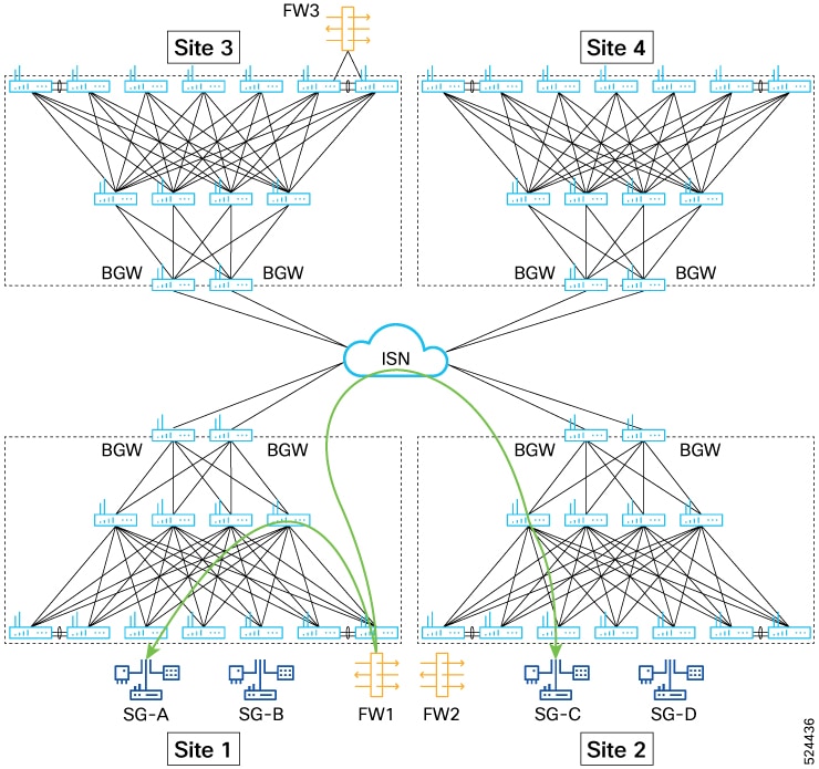
Figure 7. Service-Chain Inspection for Source and Destination Workload in Different Sites

While configuring service chain for workloads that span over multiple sites, select a service chain that is either located at the source site or the destination site. The ePBR policy is enforced on the site that has smaller security group.

Figure 8. Service Chain only in One of the Two Site (Inter site Flow) and Failover

Inter-site workload with service chain inspection, where the service chain is only present in one site. Both forward and reverse flows should traverse the same chain. In the event of service chain failure, there should be a subsequent failover to the third-site service chain for both forward and reverse flows.

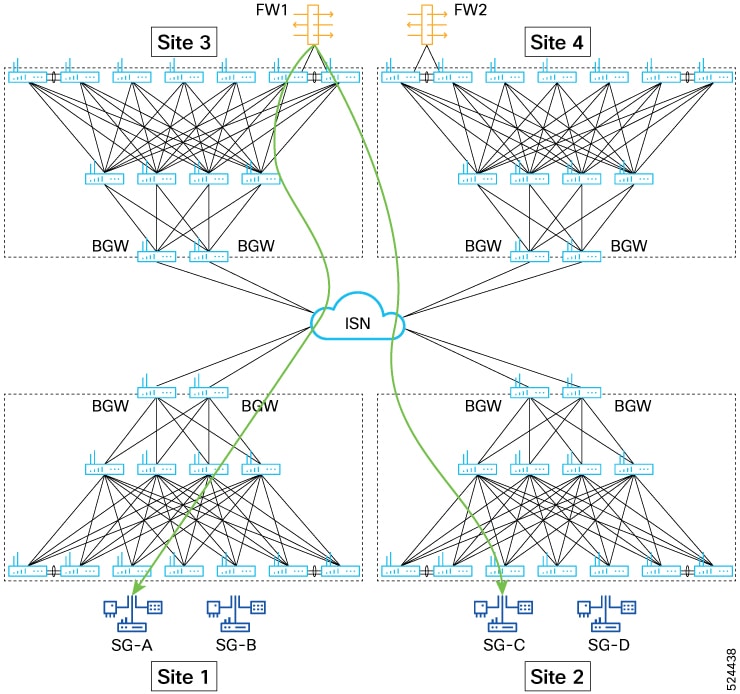
Figure 9. No Service Chain in source or destination sites

Inter-site workload with service chain inspection, where the service chain is not present in source or destination sites but only present in third site. Both forward and reverse flows should traverse the same chain.

ePBR Fail-over Group for Service-chain

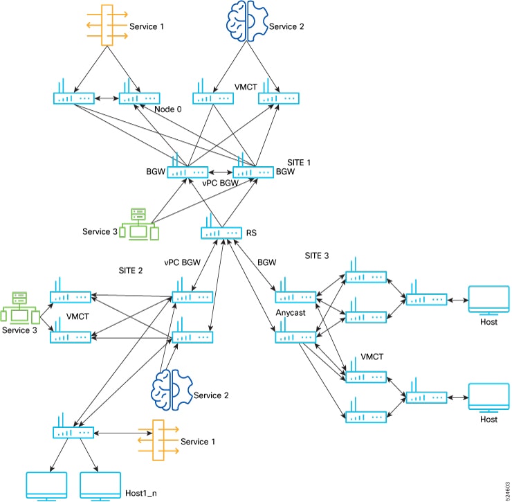
Beginning with Cisco NX-OS Release 10.5(2)F, ePBR supports fail-over groups for service-chains to allow traffic to fail-over to service-chains located in remote sites of the fabric. Fail-over group is the collection of fallback service-chains that should be used when the primary service-chain fails. Users may configure fallback service-chains and assign preferences to them based on inter-site latency, geographical proximity or capacity. The fallback service-chains need to be defined in the system before they can be referenced as a member chain inside a fail-over group of the same number of service nodes as the primary chain. A maximum of 5 member chains may be configured inside a fail-over group. The following are some of the common deployment.

Guidelines and Limitations

ePBR with micro-segmentation has the following guidelines and limitations: 

  • In NXOS 10.5(1)F SGACL based service redirection is only supported to a single service function in the chain. The service function may contain one or more layer-3 one-arm or dual-arm service endpoints.

  • Load-balancer service functions inside an GPO based ePBR service-chain may only consist of a single load-balancer endpoint.

  • Service functions with a mix of one-arm and dual-arm service endpoints are not supported.

  • The sum total of weights across all active endpoints in the ePBR service cannot exceed 128.

  • For the external load-balancer to monitor the health of the server cluster, contracts with permit action must be explicitly created between the layer4-7 security-tags of the load-balancer service and the servers.

  • Service with one-arm devices must not be configured with a reverse security-group identifier.

  • Services with dual-arm devices must be configured with a reverse security-group identifier that is different from the forward security-group. 

  • Services with dual-arm devices should use different service VLANs for the forward and reverse arms of the endpoints. The forward arms of one or more service endpoints in the service function can share one service VLAN and the reverse arms of one or more service endpoints can use a different service VLAN.

  • Users must ensure that service VLANs are used exclusively for the service endpoints and are not used for any other host traffic. Hosts cannot be connected to such VLANs. This is required to avoid incorrect classification of such traffic.

  • The forward and reverse security groups defined inside an ePBR service must be defined as layer4-7 security group selectors on the VXLAN leaf switches that have the connected interfaces (interface VLANs) configured.

  • In NXOS 10.5(1)F service endpoint connected interfaces used in services must be interface VLANs only.  Endpoint connected interfaces cannot be layer-3 physical interfaces, subinterfaces , layer-3 port-channels or port-channel subinterfaces, or any other interfaces that are supported for IPACL EPBR.

  • While security-groups and service VLANs may be shared between ePBR services, users must ensure that the contracts that use these services in chains do not have conflicting match filters or actions.

  • In NXOS 10.5(1)F, the service that the traffic is redirected to, must be configured in the same VRF context as the contract. 

  • Match class-maps for IPv4 traffic must be configured with service-chains containing IPv4 services and match class-maps for IPv6 traffic must be configured with service-chains containing IPv6 traffic.

  • Unique layer-4 source and destination port parameters should be specified for the match class-map filters, if traffic is required to match any-any source and destination security-groups in the contract and the service in the chain is a dual-arm service. 

  • Users must ensure that multiple contracts using the same source and destination security-groups are not configured with policies and match class-maps having different service redirection results for the same traffic flows.

  • When fail-action is configured for a sequence inside a service-chain , it is recommended that probing is consistently enabled for the service via service-level or endpoint-level probes.

  • It is recommended that probe traffic is classified in a separate CoPP class. Otherwise, probe traffic may use the default CoPP class and might be dropped causing continuous IP SLA state changes during spikes in supervisor traffic. For information on CoPP configuration for IP SLA, see Configuring CoPP for IP SLA Packets.

  • ePBR administrative and operational out-of-service features are not supported for services used in service redirection with micro-segmentation. For more information, see Configuring ePBR L3.

  • Endpoint states of the forward and reverse arms of dual-arm devices are not synchronized automatically. If this is needed, identical probe track configuration on the forward and reverse arms should be used.

  • Probe tracks configured for endpoints may be shared between the forward and reverse arms of the same endpoints, but not across endpoints in the same or different services.

  • Probe tracks must be used for any automatic synchronization of endpoint states across the forward and reverse arms of dual-arm devices.

  • The service nodes can be part of either the source VRF or the destination VRF or in a separate VRF. If some of the service nodes are part of the source VRF and some are a part of the destination VRF, all consecutive elements following the source, must uniformly pertain to the source VRF. Once the VRF for an element in the chain pertains to the destination VRF, all consecutive elements following this until the end of the service-chain must pertain to the destination VRF.

  • Dual-arm service end-points cannot have each arm in a different VRF.

Multinode Service-Chaining Guidelines and Limitations:

  • A maximum of 5 service functions (nodes) are supported in a service chain.

  • In multinode configuration, only bypass and drop fail-action options are supported. Fail-action option of forward is not supported.

  • Only a single service function that performs IP address translation (load-balancer or CGNAT devices) may be configured inside a multi-node service-chain.

Multi-site Service-Chaining Guidelines and Limitations:

  • All service functions for a given service chain should belong to a single site.

  • A maximum of 5 fail-over service-chains are supported inside a failover group.

  • A maximum of 10 sites are supported in a multi-site fabric that is using EPBR service-chains with VXLAN Group Policy Options.

  • Multi-Site failover options are not supported with service-chains that consist of load-balancer devices because load-balancer devices have unique VIPs and failover to a different load-balancer implies a VIP changed which is outside the scope of the VTEP making the failover decision.

  • `
  • Load-balancer devices without Source NAT enabled, used in the service-chain, and the servers they are load-balancing to must co-exist in the same site.

  • A service-chain and the fail-over service-chains it is configured to use must consist of the same number of service nodes. Each service node may, however, have a varying number of service-endpoints.

  • Every service-node inside the service-chain and the failover service-chains it is configured to use must be configured with the same service security-groups.

Configuring ePBR for Micro-segmentation

Configuring ePBR Service

Before you begin

The following section provides information about configuring ePBR services.

SUMMARY STEPS

  1. configure terminal
  2. epbr service service-name 
  3. vrf vrf-name
  4. [no] security-group <fwdGrp> [reverse<revGrp>]
  5. [no] probe {icmp | <l4-proto> <port-num> [control<status> ] | http get [ <url-name> [version <ver> ] |  dns host <host-name> ctp} [frequency <freq-num> | timeout <timeout> | retry-down-count <down-count> | retry-up-count <up-count> | source-interface <src-intf> | reverse <rev-src-intf> ]+
  6. service-endpoint {ip ipv4-address | ipv6 ipv6-address}
  7. probe track track-ID
  8. reverse {ip ipv4-address | ipv6 ipv6-address}
  9. mode hot-standby
  10. weight <weight>
  11. exit

DETAILED STEPS

  Command or Action Purpose

Step 1

configure terminal

Example:

switch# configure terminal
switch(config)#

Enters configuration mode.

Step 2

epbr service service-name 

Example:

switch(config)# epbr service firewall

Creates a new ePBR service function.

Step 3

vrf vrf-name

Example:

switch(config-epbr-svc)# vrf tenant_A

Specifies the VRF for the ePBR service function.

Step 4

[no] security-group <fwdGrp> [reverse<revGrp>]

Example:

switch(config-epbr-svc)# security-group 10 reverse 20  
switch(config-epbr-svc)# security-group 30  

Configures forward and reverse service security-group tags. For single arm devices, a single forward security-group must be specified. For dual arm devices the forward and reverse security-group must be unique.

The no form of this command removes the configuration.

Step 5

[no] probe {icmp | <l4-proto> <port-num> [control<status> ] | http get [ <url-name> [version <ver> ] |  dns host <host-name> ctp} [frequency <freq-num> | timeout <timeout> | retry-down-count <down-count> | retry-up-count <up-count> | source-interface <src-intf> | reverse <rev-src-intf> ]+

Configures the probe for the service function. The same configuration may also be applied for the forward and reverse arms of service endpoints. The no form of this command removes the configuration.

For service-endpoints distributed in a VXLAN environment, you must configure source loopback interfaces for the probe, so that a unique source IP may be used for IP SLA sessions.

Step 6

service-endpoint {ip ipv4-address | ipv6 ipv6-address}

Example:

switch(config-vrf)# service-endpoint ip 172.16.1.200  

Configures service endpoint for the ePBR service.  You can repeat steps 6 to 10 to configure another ePBR service endpoints.

Step 7

probe track track-ID

Example:

switch(config-epbr-fwd-svc)# probe track 30

Configures user-defined track for the forward or reverse arm of the service endpoint.

Step 8

reverse {ip ipv4-address | ipv6 ipv6-address}

Example:

switch(config-epbr-fwd-svc)# reverse ip 172.16.30.200

Defines the reverse IP address for dual-arm service endpoints. Note that this is not needed for one-arm endpoints.

Step 9

mode hot-standby

Example:

switch(config-epbr-fwd-svc)# mode hot-standby

Configures the service-endpoint as a hot-standby endpoint.

Step 10

weight <weight>

Example:

switch(config-epbr-fwd-svc)# weight 6

Configures the weight for the active or hot-standby endpoint.

Default value is 1.

Step 11

exit

Example:

switch(config-vrf)# exit

Exits the ePBR service configuration mode.

Configuring ePBR Service-chain

SUMMARY STEPS

  1. configure terminal
  2. [no] epbr service-chain <chain-name>
  3. [no] mode multisite [failover-group <group-name>]
  4. load-balance method <lb-method> { src-ip | dst-ip | src-dst-ipprotocol}
  5. sequence-number set service service-name[ fail-action { bypass | drop | forward}]
  6. action {route | redirect} [reverse-action {route| redirect}]

DETAILED STEPS

  Command or Action Purpose

Step 1

configure terminal

Example:

switch# configure terminal
switch(config)#

Enters configuration mode.

Step 2

[no] epbr service-chain <chain-name>

Example:

Switch(config-epbr-svc-chain)# epbr service-chain web 

Configures ePBR service-chain. The no form of this command removes the configuration.

Step 3

[no] mode multisite [failover-group <group-name>]

Example:

mode multisite failover-group fallback-web-chain3 

Beginning with NX-OS 10.5(2)F, you can configure mode multi-site and fail-over group for service-chains.

  • Fail-over groups may only be configured when mode multi-site is enabled for the service-chain. You can use the mode multi-site without using fail-over groups.

Step 4

load-balance method <lb-method> { src-ip | dst-ip | src-dst-ipprotocol}

Example:

switch(config-epbr-svc-chain)# load-balance method src-ip

Configures the load-balance method for the ePBR service-chain. The same configuration may also be applied to the individual service functions inside the service-chain.

Default option is src-dst-ipprotocol .

Step 5

sequence-number set service service-name[ fail-action { bypass | drop | forward}]

Example:

switch(config-epbr-svc-chain)# 
10 set service fw2 fail-action drop      
20 set service tcp_optim2 fail-action bypass

Specifies the service function at the specific sequence in the chain and the fail-action mechanism for that sequence.

Beginning with NX-OS 10.5(2)F, GPO with multi-node service-chain is supported.

Step 6

action {route | redirect} [reverse-action {route| redirect}]

Example:

switch(config-epbr-svc-chain-seq)# action route reverse-action route

Configure the forward and/or reverse action for the service in the chain to indicate destination and/or source NAT capabilities of the service.

Default option is redirect .

Configuring Failover Group

Follow the steps to configure the fail-over group.

SUMMARY STEPS

  1. configure terminal
  2. epbr service-chain service-chain-name
  3. epbr failover-group failover-group-name
  4. [no] service-chain <name> preference <preference>

DETAILED STEPS

  Command or Action Purpose

Step 1

configure terminal

Example:

switch# configure terminal  
switch(config)#  

Enters global configuration mode.

Step 2

epbr service-chain service-chain-name

Example:

Switch(config-epbr-svc-chain)# epbr service-chain web 

Configures service-chain.

Step 3

epbr failover-group failover-group-name

Example:

switch(config-epbr-svc-chain)# epbr failover-group fallback-web-chain1

Configures fail-over group.

Step 4

[no] service-chain <name> preference <preference>

Example:

switch(config-epbr-fail-group)# service-chain site1-web-chain preference 20 

Configure fallback service-chain inside the fail-over group and assign preferences to the fallback service-chain.

Verifying ePBR Service-chain Configuration

Use the following commands to verify the ePBR service-chain configuration:

SUMMARY STEPS

  1. show epbr service [ <svc-name> ]
  2. show epbr service-chain [ <chain-name> ] [ reverse ]
  3. show tech-support epbr
  4. show consistency-checker epbr service-chain { <svcChainName> | all }
  5. show running-config epbr
  6. show startup-config epbr

DETAILED STEPS

  Command or Action Purpose

Step 1

show epbr service [ <svc-name> ]

Example:

switch# show epbr service fw

Displays information on the ePBR service function and endpoints.

Step 2

show epbr service-chain [ <chain-name> ] [ reverse ]

Example:

switch# show epbr service-chain web

Displays information on the ePBR service-chain in forward or reverse direction.

Step 3

show tech-support epbr

Example:

switch# show tech-support epbr

Displays the technical support information for ePBR.

Step 4

show consistency-checker epbr service-chain { <svcChainName> | all }

Example:

show consistency-checker epbr service-chain web

Performs consistency checks on ePBR configuration, redirection information for ePBR in the control plane and health monitoring mechanisms that are enabled.

Step 5

show running-config epbr

Example:

switch# show running-config epbr

Displays the running configuration for ePBR.

Step 6

show startup-config epbr

Example:

switch# show startup-config epbr

Displays the startup configuration for ePBR.

Configuration Examples for SGACL service-chaining Configuration

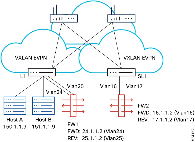
See figure 5 for the configuration example showing SGACL service-chaining configuration.

Figure 10. Configuration Example
  1. Create layer4-7 selectors for the service.

    security-group 2010 name FWD 			 
      type layer4-7							   
      match interface vlan 24 
      match interface vlan 16  
    security-group 2011 name REV  
      type layer4-7 
      match interface vlan 25 
      match interface vlan 17 
  2. Creating ePBR service and endpoints.

    epbr service fw 
      vrf tenant 
      security-group 2010 reverse 2011 
      probe tcp 80 frequency 5 timeout 3 source-interface 
       loopback10 reverse loopback11 
      service-end-point ip 10.0.1.1 
        reverse ip 10.0.1.2 
      service-end-point ip 10.0.0.1 
        reverse ip 10.0.0.2 
  3. Create security-group selectors for host traffic.

    security-group 5051 name sec_5051 
      match connected-endpoints vrf tenant ipv4 151.1.1.0/24  
    
    security-group 5050 name sec_5050 
      match connected-endpoints vrf tenant ipv4 150.1.1.0/24   
  4. Create security class-maps to define the layer3, layer-4 match criteria.

    class-map type security match-any class_ipv4_tcp 
      match ipv4 tcp dport 80 
      match ipv4 tcp dport 443 
  5. Configure the ePBR service-chain. Configuration of class-maps, policy-maps and contracts under vrf need to be consistent on all leafs.

    epbr service-chain web 
      load-balance method src-dst-ipprotocol 
      10 set service fw fail-action drop
      
  6. Configure the security policy-map and attach the service-chain to the required match class-map.

    policy-map type security web_policy 
      class type security class_ipv4_tcp 
        service-chain web 
  7. Configure the contract.

    vrf context tenant 
      security contract source 5050 destination 5051 policy web_policy 

    For more details on moving the VRF context to enforced mode, see Configuring Security contracts between Security Groups.

Verifying Configuration

  • The following example shows how to verify ePBR service and endpoint. 

    show epbr service fw   
    
    Legend:   
    
    Operational State (Op-STS):  UP:Reachable, DOWN:Unreachable,    
    
                                 SVC-ADMIN-DOWN:Service shut   
    
                                 ADMIN-DOWN:Admin shut, OPER-DOWN:Out-of-service   
    
    Probe:                       Protocol/Frequency(sec)/Timeout(sec)/Retry-Up-Count/Retry-Down-Count   
    
    Hold-down Threshold:         Count/Time(sec)   
    
    Service mode:                Full:Full-Duplex, Half:Half-Duplex   
    
    Type:                        L3:Layer-3, L2:Layer-2   
    
    Threshold:                   Threshold High/Low   


    Name                              Type      Service mode  VRF   
    
    ==========================================================================================   
    
    fw                                L3        Full          tenant                             


    Security-group    Reverse security-group   Threshold   
    
    =======================================================   
    
    2010              2011                     


    Endpoint IP/Intf         Track SLA       Op-ST          Probe               Hold-down   Role Weight 
    
    Reverse IP/Intf          Track SLA       Op-ST          Probe                  
    
    ======================================================================================   


    10.0.1.1/               1  20001     UP          TCP/5/3/0/0                                 A     1 
    
    10.0.1.2/               3   20003     UP          TCP/5/3/0/0            


    10.0.0.1/               2   20002     UP             TCP/5/3/0/0                                A     1 
    
    10.0.0.2/               4   20004     UP             TCP/5/3/0/0 
  • The following example shows how to verify the ePBR service-chain in forward or reverse direction.

    show epbr service-chain web   
    
    Service-chain : web   
    
        service:fw, sequence:10, fail-action:Drop   
    
          load-balance: Source-Destination-ipprotocol, action:Redirect   
    
          state:UP  
    
          IP 10.0.1.1 track 1 [UP]  
    
          IP 10.0.0.1 track 2 [UP]  


    show epbr service-chain web reverse    


    Service-chain : web   
    
        service:fw, sequence:10, fail-action:Drop   
    
          load-balance: Source-Destination-ipprotocol, action:Redirect   
    
          state:UP  
    
          IP 10.0.1.2 track 3 [UP] 
    
          IP 10.0.0.2 track 4 [UP]
  • The following example shows how to verify consistency checker for service-chain.

    show consistency-checker epbr service-chain chain1
    EPBR CC: Service Chain validation passed
    show consistency-checker epbr service-chain all
    EPBR CC: Service Chain validation passed
    

Configuration Example for Multi-node Single Site Service-chaining

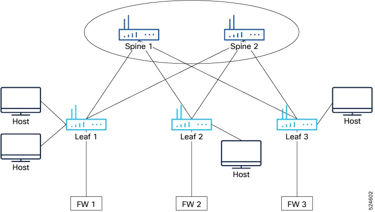
Figure 11. Configuration example

Following is a configuration example that has three firewalls as services that are part of the service chain. Each firewall is implimented with multiple service endpoints.

  1. Configuring ePBR service fw1

    epbr service fw1   
      vrf tenant 
      security-group 2010 reverse 2011 
      probe icmp frequency 2 retry-down-count 2 retry-up-count 1 timeout 1 source-interface loopback3 reverse loopback4 
      service-end-point ip 10.1.1.2 
        weight 10 
        reverse ip 11.1.1.2 
      service-end-point ip 18.1.1.2 
        reverse ip 19.1.1.2 
      service-end-point ip 20.1.1.2 
        mode hot-standby 
        reverse ip 21.1.1.2 
      service-end-point ip 253.1.1.2 
        mode hot-standby 
        weight 10 
        reverse ip 254.1.1.2 
      service-end-point ip 26.1.1.2 
        weight 5 
        reverse ip 27.1.1.2 
      service-end-point ip 34.1.1.2 
        mode hot-standby 
        weight 6 
        reverse ip 35.1.1.2 
  2. Configuring ePBR service fw2

    epbr service fw2   
      vrf tenant 
      security-group 2013 
      probe icmp frequency 2 retry-down-count 2 retry-up-count 1 timeout 1 source-interface loopback3 reverse loopback4 
      service-end-point ip 255.1.1.2 
        mode hot-standby 
      service-end-point ip 50.1.1.2 
        weight 10 
      service-end-point ip 54.1.1.2 
        weight 5 
      service-end-point ip 58.1.1.2 
      service-end-point ip 59.1.1.2 
        mode hot-standby 
        weight 10 
      service-end-point ip 62.1.1.2 
        mode hot-standby 
        weight 6 
  3. Configuring ePBR services fw3

    epbr service fw3   
      vrf tenant 
      security-group 2014 reverse 2015 
      probe icmp frequency 2 retry-down-count 2 retry-up-count 1 timeout 1 source-interface loopback3 reverse loopback4 
      service-end-point ip 12.1.1.2 
        weight 10 
        reverse ip 13.1.1.2 
      service-end-point ip 22.1.1.2 
        weight 10 
        reverse ip 23.1.1.2 
      service-end-point ip 32.1.1.2 
        weight 5 
        reverse ip 33.1.1.2 
      service-end-point ip 40.1.1.2 
        reverse ip 41.1.1.2 
  4. Configure the ePBR multi-node service-chain

    epbr service-chain FW-chain-v4 
      load-balance method dst-ip 
      10 set service service1-v4-2arm fail-action bypass  
        load-balance method src-ip 
      20 set service service3-v4-1arm fail-action drop 
      30 set service service5-v4-2arm fail-action bypass  
        load-balance method src-dst-ipprotocol 

Verifying Multi-node Service Chain

sh epbr service-chain FW-chain-v4 


Service-chain : FW-chain-v4  state:UP 

    service:fw1, sequence:10, fail-action:Bypass 

      load-balance:Source-Destination-ipprotocol, action:Redirect 

      state:UP 

      IP 10.1.1.2 track 1 [UP] 

      IP 18.1.1.2 track 2 [UP] 

      IP 26.1.1.2 track 3 [UP] 

      IP 20.1.1.2 track 4 [UP] [HOT-STANDBY] 

      IP 34.1.1.2 track 5 [UP] [HOT-STANDBY] 

      IP 253.1.1.2 track 6 [UP] [HOT-STANDBY] 

    service:fw2, sequence:20, fail-action:Drop 

      load-balance:Source-Destination-ipprotocol, action:Redirect 

      state:UP 

      IP 50.1.1.2 track 7 [UP] 

      IP 54.1.1.2 track 8 [UP] 

      IP 58.1.1.2 track 9 [UP] 

      IP 59.1.1.2 track 10 [UP] [HOT-STANDBY] 

      IP 62.1.1.2 track 11 [UP] [HOT-STANDBY] 

      IP 255.1.1.2 track 12 [UP] [HOT-STANDBY] 

    service:fw3, sequence:30, fail-action:Bypass 

      load-balance:Source-Destination-ipprotocol, action:Redirect 

      state:UP 

      IP 12.1.1.2 track 13 [UP] 

      IP 22.1.1.2 track 14 [UP] 

      IP 32.1.1.2 track 15 [UP] 

      IP 40.1.1.2 track 16 [UP] 

Configuration example for multi-site ePBR with GPO

Figure 12. Configuration example

Site 1

  1. Create security class-maps to define the layer3, layer-4 match criteria.

    class-map type security match-any web_class 
      match ipv4 tcp dport 80 
  2. Configure the security policy-map and attach the service-chain to the required match class-map

    policy-map type security web 
      class type security web_class 
        service-chain site1-web-chain 
  3. Creating ePBR service and endpoints.

    epbr service fw 
      security-group 100 
      probe icmp 
      service-end-point ip 10.1.1.2  
      service-end-point ip 20.1.1.2 
       mode hot-standby 
    
    epbr service fw2 
      security-group 100 
      probe icmp 
      service-end-point ip 11.1.1.2  
    
    epbr service fw3 
      security-group 100 
      probe icmp 
      service-end-point ip 13.1.1.2 
  4. Configuring Multi-site mode and fail over group and chain

    epbr service-chain site1-web-chain 
      mode multisite failover-group fallback-web-chain1 
      load-balance method dst-ip 
      10 set service fw fail-action drop         
    
    epbr service-chain site2-web-chain 
      load-balance method dst-ip 
      10 set service fw2 fail-action drop      
    
    epbr service-chain site3-web-chain 
      load-balance method dst-ip 
      10 set service fw3 fail-action drop    
    
    epbr failover-group fallback-web-chain1 
      service-chain site2-web-chain preference 5 
      service-chain site3-web-chain preference 20 

Site 2

  1. Create security class-maps to define the layer3, layer-4 match criteria.

     class-map type security match-any web_class 
      match ipv4 tcp dport 80 
  2. Configure the security policy-map and attach the service-chain to the required match class-map.

    policy-map type security web 
      class type security web_class 
        service-chain site2-web-chain 
  3. Creating ePBR service and endpoints.

    epbr service fw 
      security-group 100 
      probe icmp 
      service-end-point ip 10.1.1.2  
      service-end-point ip 20.1.1.2 
       mode hot-standby 
    
     epbr service fw2 
      security-group 100 
      probe icmp 
      service-end-point ip 11.1.1.2  
    
    epbr service fw3 
      security-group 100 
      probe icmp 
      service-end-point ip 13.1.1.2 
  4. Configuring Multi-site mode and fail over group and chain

    epbr service-chain site1-web-chain 
      load-balance method dst-ip 
      10 set service fw fail-action drop          
    
    epbr service-chain site2-web-chain 
      mode multisite failover-group fallback-web-chain2 
      load-balance method dst-ip 
      10 set service fw2 fail-action drop      
    
    epbr service-chain site3-web-chain 
      load-balance method dst-ip 
      10 set service fw3 fail-action drop    
    
    epbr failover-group fallback-web-chain2 
      service-chain site1-web-chain preference 5 
      service-chain site3-web-chain preference 25 

Site 3

  1. Create security class-maps to define the layer3, layer-4 match criteria.

    class-map type security match-any web_class 
      match ipv4 tcp dport 80 
  2. Configure the security policy-map and attach the service-chain to the required match class-map

    policy-map type security web 
      class type security web_class 
        service-chain site3-web-chain 
  3. Creating ePBR service and endpoints

    epbr service fw 
      security-group 100 
      probe icmp 
      service-end-point ip 10.1.1.2  
      service-end-point ip 20.1.1.2 
       mode hot-standby 
    
    
    epbr service fw2 
      security-group 100 
      probe icmp 
      service-end-point ip 11.1.1.2  
    
    epbr service fw3 
      security-group 100 
      probe icmp 
      service-end-point ip 13.1.1.2 
  4. Configuring service-chain and multi-site

    epbr service-chain site1-web-chain 
      load-balance method dst-ip 
      10 set service fw fail-action drop         
    
    
    epbr service-chain site2-web-chain 
      load-balance method dst-ip 
      10 set service fw2 fail-action drop      
    
     epbr service-chain site3-web-chain 
      mode multisite failover-group fallback-web-chain3  
      load-balance method dst-ip 
      10 set service fw3 fail-action drop    
  5. Configure failover group

    epbr failover-group fallback-web-chain3 
      service-chain site1-web-chain preference 20 
      service-chain site2-web-chain preference 25 

Verifying Multi-site Configuration

You can use the following show commands to verify multi-site configuration.

  • The following example shows how to verify ePBR service-chain state. 

    show epbr service-chain site1-web-chain   
    Service-chain : site1-web-chain 	state:DOWN 
                                                           
    
      mode: multisite, failover-group:fallback-web-chain [AVAILABLE][IN USE]  failover-chain: site3-web-chain     
        service:fw, sequence:10, fail-action:Drop                               
          load-balance:Destination-ip, action:Redirect 
          state:DOWN                                                              
          IP 10.1.1.2 track 9 [DOWN]                     
          IP 20.1.1.2 track 10 [DOWN][HOT-STANDBY]                                 
        service:tcp_optim, sequence:20, fail-action:Bypass                        
          load-balance:Destination-ip, action:Redirect 
          state:UP                                                                
          IP 30.1.1.2 track 11 [UP] 
  • The following example shows how to get the details of the failover chains inside the failover group.

    show epbr failover-group fallback-web-chain 
    
    Failover group : fallback-web-chain 
        Failover Service-chain : site2-web-chain  Preference: 1  state: DOWN 
          service:fw2, sequence:10, fail-action:Drop 
            load-balance:Destination-ip, action:Redirect 
            state:DOWN 
            IP 11.1.1.2 track 12 [DOWN]  
          service:tcp_optim2, sequence:20, fail-action:Bypass 
            state: UP 
            load-balance:Destination-ip, action:Redirect 
            state:UP                                                                      
            IP 12.1.1.2 track 13 [UP] 
    
        Failover Service-chain : site3-web-chain  Preference: 2  state: UP 
          service:fw3, sequence:10, fail-action:Drop 
            load-balance:Destination-ip, action:Redirect 
            state:UP 
            IP 13.1.1.2 track 14 [UP]                
          service:tcp_optim2, sequence:20, fail-action:Bypass 
            load-balance:Destination-ip, action:Redirect 
            state:UP                                                                      
            IP 14.1.1.2 track 15 [UP]