- Index
- Preface
- Overview of the VPN Services Port Adapter
- Overview of the IPsec Features
- Configuring VPNs in Crypto-Connect Mode
- Configuring VPNs in VRF Mode
- Configuring IPSec VPN Fragmentation and MTU
- Configuring Quality of Service
- Configuring IKE Features
- Configuring Enhanced IPsec Features
- Configuring PKI
- Configuring Advanced VPNs
- Configuring Duplicate Hardware and IPsec Failover
- Configuring Monitoring and Accounting
- Troubleshooting
Cisco VPN Services Port Adapter Configuration Guide
Bias-Free Language
The documentation set for this product strives to use bias-free language. For the purposes of this documentation set, bias-free is defined as language that does not imply discrimination based on age, disability, gender, racial identity, ethnic identity, sexual orientation, socioeconomic status, and intersectionality. Exceptions may be present in the documentation due to language that is hardcoded in the user interfaces of the product software, language used based on RFP documentation, or language that is used by a referenced third-party product. Learn more about how Cisco is using Inclusive Language.
- Updated:
- November 11, 2008
Chapter: Configuring Duplicate Hardware and IPsec Failover
- Overview of Duplicate Hardware Configurations and IPsec Failover
- Configuring IPsec Stateless Failover
- Configuring Intrachassis IPsec Stateful Failover Using a Blade Failure Group
- Configuration Examples
Configuring Duplicate Hardware and IPsec Failover
This chapter provides information about configuring duplicate hardware and IPsec failover using the VSPA on the Catalyst 6500 Series switch. It includes the following sections:
•![]() Overview of Duplicate Hardware Configurations and IPsec Failover
Overview of Duplicate Hardware Configurations and IPsec Failover
•![]() Configuring IPsec Stateless Failover
Configuring IPsec Stateless Failover
•![]() Configuring Intrachassis IPsec Stateful Failover Using a Blade Failure Group
Configuring Intrachassis IPsec Stateful Failover Using a Blade Failure Group

Note ![]() For detailed information on Cisco IOS IPsec cryptographic operations and policies, see the Cisco IOS Security Configuration Guide, Release 12.2 at this URL:
For detailed information on Cisco IOS IPsec cryptographic operations and policies, see the Cisco IOS Security Configuration Guide, Release 12.2 at this URL:
http://www.cisco.com/en/US/docs/ios/12_2/security/configuration/guide/fsecur_c.html
For more information about the commands used in this chapter, see the Cisco IOS Security Command Reference at this URL:
http://www.cisco.com/en/US/docs/ios/security/command/reference/sec_book.html
Also refer to the related Cisco IOS Release 12.2 software configuration guide, command reference, and master index publications. For more information about accessing these publications, see the "Related Documentation" section on page xvi.

Tip ![]() To ensure a successful configuration of your VPN using the VSPA, read all of the configuration summaries and guidelines before you perform any configuration tasks.
To ensure a successful configuration of your VPN using the VSPA, read all of the configuration summaries and guidelines before you perform any configuration tasks.
Overview of Duplicate Hardware Configurations and IPsec Failover
For critical VPN communications, you can deploy redundant VPN hardware and configure your system for failover in case of hardware failure. The following topics provide information about configuring for IPsec failover using the VSPA:
•![]() Configuring Multiple VSPAs in a Chassis
Configuring Multiple VSPAs in a Chassis
•![]() Understanding Stateless Failover Using HSRP
Understanding Stateless Failover Using HSRP
•![]() IPsec Stateless Failover Configuration Guidelines and Restrictions
IPsec Stateless Failover Configuration Guidelines and Restrictions
Configuring Multiple VSPAs in a Chassis
You can deploy up to ten VSPAs in a single chassis, with the restriction that no more than one VSPA can be used to perform IPsec services for any given interface VLAN.
Multiple VSPAs in a Chassis Configuration Guidelines
When configuring multiple VSPAs in a chassis, follow these guidelines:
•![]() Using the no switchport command followed by the switchport command readds all VLANs to a trunk port (this situation occurs when you are first switching to a routed port and then back to a switch port). For detailed information on configuring trunk ports, see "Configuring a Trunk Port" section on page 3-14 of Chapter 3, "Configuring VPNs in Crypto-Connect Mode."
Using the no switchport command followed by the switchport command readds all VLANs to a trunk port (this situation occurs when you are first switching to a routed port and then back to a switch port). For detailed information on configuring trunk ports, see "Configuring a Trunk Port" section on page 3-14 of Chapter 3, "Configuring VPNs in Crypto-Connect Mode."
•![]() As with single VSPA deployments, you must properly configure each VSPA's inside and outside port. You can add an interface VLAN only to the inside port of one VSPA. Do not add the same interface VLAN to the inside port of more than one VSPA.
As with single VSPA deployments, you must properly configure each VSPA's inside and outside port. You can add an interface VLAN only to the inside port of one VSPA. Do not add the same interface VLAN to the inside port of more than one VSPA.
Assigning interface VLANs to the inside ports of the VSPAs allows you to decide which VSPA can be used to provide IPsec services for a particular interface VLAN.
Note ![]() You do not need to explicitly add interface VLANs to the inside trunk ports of the VSPAs. Entering the crypto engine slot command achieves the same results.
You do not need to explicitly add interface VLANs to the inside trunk ports of the VSPAs. Entering the crypto engine slot command achieves the same results.
Note ![]() There is no support for using more than one VSPA to do IPsec processing for a single interface VLAN.
There is no support for using more than one VSPA to do IPsec processing for a single interface VLAN.
•![]() SA-based load balancing is not supported.
SA-based load balancing is not supported.
•![]() If you assign the same crypto map to multiple interfaces, then you must use the crypto map local address command, and all interfaces must be assigned to the same crypto engine.
If you assign the same crypto map to multiple interfaces, then you must use the crypto map local address command, and all interfaces must be assigned to the same crypto engine.
For a configuration example of multiple VSPAs in a chassis, see the "Multiple VSPAs in a Chassis Configuration Example" section.
Understanding Stateless Failover Using HSRP
The IPsec failover (VPN high availability) feature allows you to employ a secondary (standby) switch that automatically takes over the primary (active) switch's tasks in the event of an active switch failure. IPsec failover, stateless or stateful, is designed to work in conjunction with the Hot Standby Routing Protocol (HSRP) and Reverse Route Injection (RRI).
HSRP is used between the active and standby switch in either stateless or stateful mode, tracking the state of switch interfaces and providing a failover mechanism between primary and secondary devices. An HSRP group shares a single virtual IP address as its crypto peer address so that the remote crypto peer requires no reconfiguration after a failover. The configured HSRP timers determine the time that it takes for the standby switch to take over.
RRI uses information derived from the negotiated IPsec SAs to create static routes to the networks identified in those SAs. During an HSRP and IPsec failover, RRI allows dynamic routing information updates.
In an IPsec stateless failover, the HSRP group's virtual IP address transfers over to the standby switch, but no IPsec or ISAKMP SA state information is transferred to the standby switch. The remote crypto peer detects the failure using Dead Peer Detection (DPD) or a keepalive mechanism. The remote crypto peer then communicates with the standby switch at the HSRP group address to renegotiate the dropped ISAKMP SAs and IPsec SAs before traffic transmission can resume.
When used together, HSRP and RRI provide a reliable network design for VPNs and reduce configuration complexity on remote peers.
For complete HSRP configuration information, refer to this URL:
http://www.cisco.com/en/US/tech/tk583/tk372/technologies_tech_note09186a00800942f7.shtml
IPsec Stateless Failover Configuration Guidelines and Restrictions
When configuring IPsec stateless failover, follow these guidelines and restrictions:
•![]() When configuring IPsec stateless failover with the VSPA, all VSPA configuration rules apply. You must apply crypto maps to interface VLANs.
When configuring IPsec stateless failover with the VSPA, all VSPA configuration rules apply. You must apply crypto maps to interface VLANs.
•![]() The recommended HSRP timer values are one second for hello timers and three seconds for hold timers. These values should prevent an undesirable failover that is caused by temporary network congestion or transient high CPU loads.
The recommended HSRP timer values are one second for hello timers and three seconds for hold timers. These values should prevent an undesirable failover that is caused by temporary network congestion or transient high CPU loads.
These timer values can be adjusted upward if you are running high loads or have a large number of HSRP groups. Temporary failures and load-related system stability can be positively affected by raising the timer values as needed. The hello timer value should be approximately a third of the hold timer value.
•![]() The standby preempt command is required, and should be configured with no priority or delay options.
The standby preempt command is required, and should be configured with no priority or delay options.
•![]() To allow dynamic routing information updates during the HSRP and IPsec failover, enable the Reverse Route Injection (RRI) feature using the reverse-route command.
To allow dynamic routing information updates during the HSRP and IPsec failover, enable the Reverse Route Injection (RRI) feature using the reverse-route command.
•![]() To verify that all processes are running properly after enabling HSRP, use the show standby command.
To verify that all processes are running properly after enabling HSRP, use the show standby command.
•![]() The following features are not supported with IPsec stateless failover:
The following features are not supported with IPsec stateless failover:
–![]() The standby use-bia command—Always use a virtual HSRP MAC address for the switch's MAC address.
The standby use-bia command—Always use a virtual HSRP MAC address for the switch's MAC address.
–![]() DMVPN or tunnel protection.
DMVPN or tunnel protection.
–![]() Secured WAN ports (for example, IPsec over FlexWAN or SIP module port adapters)— This restriction is due to limitations of HSRP.
Secured WAN ports (for example, IPsec over FlexWAN or SIP module port adapters)— This restriction is due to limitations of HSRP.
Configuring IPsec Stateless Failover
Note ![]() IPsec stateful failover is supported only within a chassis using a blade failure group, as described in "Configuring Intrachassis IPsec Stateful Failover Using a Blade Failure Group" section. Inter-chassis stateful failover is not supported.
IPsec stateful failover is supported only within a chassis using a blade failure group, as described in "Configuring Intrachassis IPsec Stateful Failover Using a Blade Failure Group" section. Inter-chassis stateful failover is not supported.
The following sections describe how to configure IPsec stateless failover in crypto-connect and VRF modes:
•![]() Configuring IPsec Stateless Failover Using HSRP with Crypto-Connect Mode
Configuring IPsec Stateless Failover Using HSRP with Crypto-Connect Mode
•![]() Configuring IPsec Stateless Failover with VRF Mode
Configuring IPsec Stateless Failover with VRF Mode
Configuring IPsec Stateless Failover Using HSRP with Crypto-Connect Mode
To configure IP stateless failover using HSRP, perform this task beginning in global configuration mode:
For examples of IPsec stateless failover configurations using HSRP, see the "IPsec Stateless Failover Using HSRP with Crypto-Connect Mode Configuration Examples" section.
Configuring IPsec Stateless Failover with VRF Mode
Chassis-to-chassis failover with VRF mode is configured differently from non-VRF (crypto-connect) mode. In VRF mode, the HSRP configuration goes on the physical interface, but the crypto map is added to the interface VLAN. In non-VRF mode, both the HSRP configuration and the crypto map are on the same interface. RRI dynamically inserts and removes routes from the active and standby switch VRF routing tables.
For a configuration example of VRF mode with stateless failover, see the "IPsec Stateless Failover Using HSRP with VRF Mode Configuration Example" section.
Configuring Intrachassis IPsec Stateful Failover Using a Blade Failure Group
This section describes how to configure IPsec stateful failover within a chassis using a blade failure group (BFG).
Note ![]() IPsec stateful failover is only supported within a chassis using a blade failure group. Inter-chassis failover is not supported.
IPsec stateful failover is only supported within a chassis using a blade failure group. Inter-chassis failover is not supported.
When one or more pairs of VSPAs are installed in a chassis, each pair can be configured as a blade failure group (BFG). The two modules do not need to reside within the same SSC. Within the BFG, each VSPA serves as a backup for the other VSPA. A BFG is an active/active configuration.
When a VSPA is joining a BFG or booting to come online, all of its IPsec and IKE data structures are synchronized with its peer. For each IPsec tunnel or IKE SA, and based on the per-interface crypto engine assignment, only one VSPA can be designated as active. For IKE SAs, an active VSPA is the one that is accelerating cryptographic computations. For IPsec tunnels, the active VSPA is the one that the traffic is passing through. For each IKE SA or IPsec tunnel, there is an active VSPA and its backup. For example, in a system that supports 1000 tunnels with two VSPAs, 500 of the tunnels may be active on one VSPA and the remaining 500 may be active on the second VSPA. Both VSPAs then replicate data to each other so that either one can take over in the event of a failure. Each VSPA can have only one partner for all of the IKE and IPsec SAs that it protects.
IPsec Stateful Failover Using a BFG Configuration Guidelines
When configuring IPsec stateful failover using a BFG, follow these guidelines:
•![]() You can install or remove one of the VSPAs comprising a BFG without disrupting any of the tunnels on the other VSPA.
You can install or remove one of the VSPAs comprising a BFG without disrupting any of the tunnels on the other VSPA.
Configuring a BFG for IPsec Stateful Failover
To configure IPsec stateful failover using a BFG, perform this task beginning in global configuration mode:
For an IPsec stateful failover using a BFG configuration example, see the "IPsec Stateful Failover Using a Blade Failure Group Configuration Example" section.
Verifying the IPsec Stateful Failover Using a BFG Configuration
To verify the IPsec stateful failover using a BFG configuration, use the show redundancy linecard group and show crypto ace redundancy commands.
To display the components of a Blade Failure Group, enter the show redundancy linecard group command:
Router# show redundancy linecard-group 1
Line Card Redundancy Group:1 Mode:feature-card
Class:load-sharing
Cards:
Slot:3 Sublot:0
Slot:5 Sublot:0
To display information about a Blade Failure Group, enter the show crypto ace redundancy command:
Router# show crypto ace redundancy
--------------------------------------
LC Redundancy Group ID :1
Pending Configuration Transactions:0
Current State :OPERATIONAL
Number of blades in the group :2
Slots
--------------------------------------
Slot:3 subslot:0
Slot state:0x36
Booted
Received partner config
Completed Bulk Synchronization
Crypto Engine in Service
Rebooted 22 times
Initialization Timer not running
Slot:5 subslot:0
Slot state:0x36
Booted
Received partner config
Completed Bulk Synchronization
Crypto Engine in Service
Rebooted 24 times
Initialization Timer not running
Configuration Examples
This section provides examples of the following configurations:
•![]() Multiple VSPAs in a Chassis Configuration Example
Multiple VSPAs in a Chassis Configuration Example
•![]() IPsec Stateless Failover Using HSRP with Crypto-Connect Mode Configuration Examples
IPsec Stateless Failover Using HSRP with Crypto-Connect Mode Configuration Examples
•![]() IPsec Stateless Failover Using HSRP with VRF Mode Configuration Example
IPsec Stateless Failover Using HSRP with VRF Mode Configuration Example
•![]() IPsec Stateful Failover Using a Blade Failure Group Configuration Example
IPsec Stateful Failover Using a Blade Failure Group Configuration Example
Multiple VSPAs in a Chassis Configuration Example
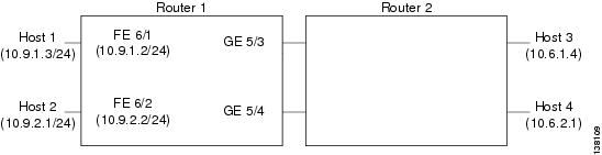
This section provides an example of a configuration using multiple VSPAs in a chassis as shown in Figure 11-1. Note the following in these examples:
•![]() A VSPA is in slot 2, subslot 0 and slot 3, subslot 0 of router 1.
A VSPA is in slot 2, subslot 0 and slot 3, subslot 0 of router 1.
•![]() In the configuration example, three exclamation points (!!!) precede descriptive comments.
In the configuration example, three exclamation points (!!!) precede descriptive comments.
Note ![]() In the following figure, the router with the VSPA could be a Cisco 7600 Series router or a Catalyst 6500 Series switch.
In the following figure, the router with the VSPA could be a Cisco 7600 Series router or a Catalyst 6500 Series switch.
Figure 11-1 Multiple VSPAs in a Chassis Configuration Example
crypto isakmp policy 1
encr 3des
hash md5
authentication pre-share
group 2
crypto isakmp key mykey address 10.8.1.1
crypto isakmp key mykey address 10.13.1.1
!
crypto ipsec transform-set xform1 ah-md5-hmac esp-des esp-sha-hmac
crypto ipsec transform-set xform2 esp-3des esp-sha-hmac
!
!!! crypto map applied to VLAN 12, which is
!!! assigned to "inside" port of VSPA in slot 3
crypto map cmap2 10 ipsec-isakmp
set peer 10.8.1.1
set transform-set xform1
match address 102
!
!!! crypto map applied to VLAN 20, which is
!!! assigned to "inside" port of VSPA in slot 2/0
crypto map cmap3 10 ipsec-isakmp
set peer 10.13.1.1
set transform-set xform2
match address 103
!
!!! "port" VLAN, crypto connected to VLAN 12 by VSPA on slot 3/0
interface Vlan11
no ip address
crypto connect vlan 12
!
!!! "interface" VLAN, assigned to VSPA on slot 3/0
interface Vlan12
ip address 10.8.1.2 255.255.0.0
crypto map cmap2
crypto engine slot 3/0
!
!!! "port" VLAN, crypto connected to VLAN 20 by VSPA on slot 2/0
interface Vlan19
no ip address
crypto connect vlan 20
!
!!! "interface" VLAN, assigned to VSPA on slot 2/0
interface Vlan20
ip address 10.13.1.2 255.255.0.0
crypto map cmap3
crypto engine slot 2/0
!
!!! connected to Host 1
interface FastEthernet6/1
ip address 10.9.1.2 255.255.255.0
!
!!! connected to Host 2
interface FastEthernet6/2
ip address 10.9.2.2 255.255.255.0
!
!!! connected to Router 2
interface GigabitEthernet5/3
switchport
switchport mode access
switchport access vlan 11
!
!!! connected to Router 2
interface GigabitEthernet5/4
switchport
switchport mode access
switchport access vlan 19
!
interface GigabitEthernet2/0/1
no ip address
flowcontrol receive on
switchport
switchport trunk encapsulation dot1q
switchport trunk allowed vlan 12,1002-1005
switchport mode trunk
cdp enable
!
interface GigabitEthernet2/0/2
no ip address
flowcontrol receive on
switchport
switchport trunk encapsulation dot1q
switchport trunk allowed vlan 11,1002-1005
switchport mode trunk
cdp enable
!
interface GigabitEthernet3/0/1
no ip address
flowcontrol receive on
switchport
switchport trunk encapsulation dot1q
switchport trunk allowed vlan 20,1002-1005
switchport mode trunk
cdp enable
!
interface GigabitEthernet3/0/2
no ip address
flowcontrol receive on
switchport
switchport trunk encapsulation dot1q
switchport trunk allowed vlan 19,1002-1005
switchport mode trunk
cdp enable
!
ip classless
!
!!! packets from Host 1 to Host 3 are routed from FastEthernet6/1
!!! to VLAN 12, encrypted with crypto map cmap2
!!! using VSPA in slot 3/0, and forwarded to peer 10.8.1.1
!!! through GigabitEthernet5/3
ip route 10.6.1.4 255.255.255.255 10.8.1.1
!
!!! packets from Host 2 to Host 4 are routed from FastEthernet6/2
!!! to VLAN 20, encrypted with crypto map cmap3
!!! using VSPA in slot 2/0, and forwarded to peer 10.13.1.1
!!! through GigabitEthernet5/4
ip route 10.6.2.1 255.255.255.255 10.13.1.1
!
!!! ACL matching traffic between Host 1 and Host 3
access-list 102 permit ip host 10.9.1.3 host 10.6.1.4
!
!!! ACL matching traffic between Host 2 and Host 4
access-list 103 permit ip host 10.9.2.1 host 10.6.2.1
IPsec Stateless Failover Using HSRP with Crypto-Connect Mode Configuration Examples
This section provides the following configuration examples of IPsec stateless failover using HSRP:
•![]() IPsec Stateless Failover for the Active Chassis Configuration Example
IPsec Stateless Failover for the Active Chassis Configuration Example
•![]() IPsec Stateless Failover for the Remote Switch Configuration Example
IPsec Stateless Failover for the Remote Switch Configuration Example
IPsec Stateless Failover for the Active Chassis Configuration Example
The following example shows the configuration for an active chassis that is configured for IPsec stateless failover using HSRP:
hostname router-1
!
vlan 2-1001
!
crypto isakmp policy 1
encr 3des
hash md5
authentication pre-share
group 2
crypto isakmp key 1234567890 address 0.0.0.0 0.0.0.0
!
!
crypto ipsec transform-set PYTHON esp-3des
!
crypto dynamic-map dynamap_1 20
set transform-set PYTHON
reverse-route
!
!
crypto map MONTY 1 ipsec-isakmp dynamic dynamap_1
!
interface GigabitEthernet1/3
switchport
switchport access vlan 502
switchport mode access
!
interface GigabitEthernet1/4
ip address 50.0.0.3 255.0.0.0
!
interface GigabitEthernet4/0/1
switchport
switchport trunk encapsulation dot1q
switchport trunk allowed vlan 2
switchport mode trunk
mtu 9216
flowcontrol receive on
flowcontrol send off
spanning-tree portfast trunk
!
interface GigabitEthernet4/0/2
switchport
switchport trunk encapsulation dot1q
switchport trunk allowed vlan 502
switchport mode trunk
mtu 9216
flowcontrol receive on
flowcontrol send off
spanning-tree portfast trunk
!
interface Vlan2
ip address 172.1.1.3 255.255.255.0
standby ip 172.1.1.100
standby preempt
standby name KNIGHTSOFNI
standby track GigabitEthernet1/3
standby track GigabitEthernet1/4
no mop enabled
crypto map MONTY redundancy KNIGHTSOFNI
crypto engine slot 4/0
!
interface Vlan502
no ip address
crypto connect vlan 2
!
ip route 10.0.0.0 255.0.0.0 172.1.1.4
ip route 20.0.0.0 255.0.0.0 172.1.1.4
ip route 50.0.0.0 255.0.0.0 50.0.0.13
ip route 50.0.1.1 255.255.255.255 50.0.0.13
ip route 50.0.2.1 255.255.255.255 50.0.0.13
ip route 50.0.3.1 255.255.255.255 50.0.0.13
ip route 50.0.4.1 255.255.255.255 50.0.0.13
ip route 50.0.5.1 255.255.255.255 50.0.0.13
IPsec Stateless Failover for the Remote Switch Configuration Example
The following example shows the configuration for a remote switch that is configured for IPsec stateless failover using HSRP:
hostname router-remote
!
crypto isakmp policy 1
encr 3des
hash md5
authentication pre-share
group 2
crypto isakmp key 12345 address 172.1.1.100
!
!
crypto ipsec transform-set ha_transform esp-3des
!
crypto map test_1 local-address Vlan2
crypto map test_1 10 ipsec-isakmp
set peer 172.1.1.100
set security-association lifetime seconds 86400
set transform-set ha_transform
set pfs group2
match address test_1
!
interface GigabitEthernet1/1
ip address 10.0.0.2 255.255.255.0
!
interface GigabitEthernet1/2
switchport
switchport trunk encapsulation dot1q
switchport trunk allowed vlan 1,502,1002-1005
switchport mode trunk
!
interface GigabitEthernet4/0/1
switchport
switchport trunk encapsulation dot1q
switchport trunk allowed vlan 1-2,1002-1005
switchport mode trunk
mtu 9216
flowcontrol receive on
flowcontrol send off
spanning-tree portfast trunk
!
interface GigabitEthernet4/0/2
switchport
switchport trunk encapsulation dot1q
switchport trunk allowed vlan 1,502,1002-1005
switchport mode trunk
mtu 9216
flowcontrol receive on
flowcontrol send off
spanning-tree portfast trunk
!
interface Vlan2
ip address 20.0.1.1 255.255.255.0
crypto map test_1
crypto engine slot 4/0
!
interface Vlan502
no ip address
crypto connect vlan 2
!
ip route 10.0.0.0 255.0.0.0 10.0.0.13
ip route 50.0.1.0 255.255.255.0 20.0.1.2
ip route 172.1.1.0 255.255.255.0 20.0.1.2
!
ip access-list extended test_1
permit ip host 10.0.1.1 host 50.0.1.1
IPsec Stateless Failover Using HSRP with VRF Mode Configuration Example
The following example shows a VRF mode configuration with HSRP chassis-to-chassis stateless failover with crypto maps:
hostname router-1
!
ip vrf ivrf
rd 1000:1
route-target export 1000:1
route-target import 1000:1
!
crypto engine mode vrf
!
vlan 2,3
!
crypto keyring key1
pre-shared-key address 14.0.1.1 key 12345
!
crypto isakmp policy 1
encr 3des
hash md5
authentication pre-share
crypto isakmp keepalive 10
crypto isakmp profile ivrf
vrf ivrf
keyring key1
match identity address 14.0.1.1 255.255.255.255
!
crypto ipsec transform-set ts esp-3des esp-sha-hmac
!
crypto map map_vrf_1 local-address Vlan3
crypto map map_vrf_1 10 ipsec-isakmp
set peer 14.0.1.1
set transform-set ts
set isakmp-profile ivrf
match address acl_1
!
interface GigabitEthernet1/1
!switch inside port
ip address 13.254.254.1 255.255.255.0
!
interface GigabitEthernet1/1.1
encapsulation dot1Q 2000
ip vrf forwarding ivrf
ip address 13.254.254.1 255.0.0.0
!
interface GigabitEthernet1/2
!switch outside port
switchport
switchport access vlan 3
switchport mode access
!
interface GigabitEthernet4/0/1
!VSPA inside port
switchport
switchport trunk encapsulation dot1q
switchport trunk allowed vlan 1,2,1002-1005
switchport mode trunk
mtu 9216
flowcontrol receive on
flowcontrol send off
spanning-tree portfast trunk
!
interface GigabitEthernet4/0/2
!VSPA outside port
switchport
switchport trunk encapsulation dot1q
switchport trunk allowed vlan 1,1002-1005
switchport mode trunk
mtu 9216
flowcontrol receive on
flowcontrol send off
spanning-tree portfast trunk
!
interface Vlan3
ip address 15.0.0.2 255.255.255.0
standby delay minimum 0 reload 0
standby 1 ip 15.0.0.100
standby 1 timers msec 100 1
standby 1 priority 105
standby 1 preempt
standby 1 name std-hsrp
standby 1 track GigabitEthernet1/2
crypto engine outside
!
interface Vlan2
ip vrf forwarding ivrf
ip address 15.0.0.252 255.255.255.0
crypto map map_vrf_1 redundancy std-hsrp
crypto engine slot 4/0 inside
!
ip classless
ip route 12.0.0.0 255.0.0.0 15.0.0.1
ip route 13.0.0.0 255.0.0.0 13.254.254.2
ip route 14.0.0.0 255.0.0.0 15.0.0.1
ip route 223.255.254.0 255.255.255.0 17.1.0.1
ip route vrf ivrf 12.0.0.1 255.255.255.255 15.0.0.1
!
ip access-list extended acl_1
permit ip host 13.0.0.1 host 12.0.0.1
!
!
arp vrf ivrf 13.0.0.1 0000.0000.2222 ARPA
IPsec Stateful Failover Using a Blade Failure Group Configuration Example
The following example shows how to configure IPsec stateful failover using a blade failure group (BFG):
Router(config)# redundancy
Router(config-red)# linecard-group 1 feature-card
Router(config-r-lc)# subslot 3/1
Router(config-r-lc)# subslot 5/1
 Feedback