- Preface
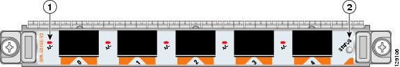
- Overview: Cisco XR 12000 Series Router SPA Interface Processors
- Overview: Cisco XR 12000 Series Router Shared Port Adaptors
- Preparing to Install a Shared Port Adapter or a SPA Interface Processor
- Installing and Removing a SPA Interface Processor
- Installing and Removing a Shared Port Adapter
- Troubleshooting the Installation
- Glossary
Cisco XR 12000 Series Router SIP and SPA Hardware Installation Guide
Bias-Free Language
The documentation set for this product strives to use bias-free language. For the purposes of this documentation set, bias-free is defined as language that does not imply discrimination based on age, disability, gender, racial identity, ethnic identity, sexual orientation, socioeconomic status, and intersectionality. Exceptions may be present in the documentation due to language that is hardcoded in the user interfaces of the product software, language used based on RFP documentation, or language that is used by a referenced third-party product. Learn more about how Cisco is using Inclusive Language.
- Updated:
- June 16, 2016
Chapter: Overview: Cisco XR 12000 Series Router Shared Port Adaptors
- SPA Summary
- Bandwidth Oversubscription
- 2-Port and 4-Port T3/E3 Serial SPA Overview
- 2-Port and 4-Port Channelized T3 to DS0 SPA Overview
- 8-Port Channelized T1/E1 SPA Overview
- 8 Port FastEthernet SPA Overview
- 1 Port 10-Gigabit Ethernet SPA Overview
Overview: Cisco XR 12000 Series Router Shared Port Adapters
This chapter describes the shared port adapters (SPAs) that are supported on the Cisco XR 12000 Series Router and contains the following sections:
- SPA Summary
- Bandwidth Oversubscription
- 2-Port and 4-Port T3/E3 Serial SPA Overview
- 2-Port and 4-Port Channelized T3 to DS0 SPA Overview
- 8-Port Channelized T1/E1 SPA Overview
- 8 Port FastEthernet SPA Overview
- 1 Port 10-Gigabit Ethernet SPA Overview
- 2-Port Gigabit Ethernet SPA Overview
- 5-Port Gigabit Ethernet SPA Overview
- 10-Port Gigabit Ethernet SPA Overview
- 1-Port Channelized STM-1/OC-3 SPA Overview
- 1-Port Channelized STM-4/OC-12 SPA Overview
- 1-Port OC-192/STM-64 POS SPA Overview
- 1-Port OC-192/STM-64 POS SPA Overview
- 1-Port OC-192 STM-64 POS RPR XFP SPA Overview
- 4-Port OC-3/STM-1 POS SPA Overview
- 8-Port OC-3 STM-1/OC-12 STM-4 POS SPA Overview
- 1-Port OC-12/STM-4 POS SPA Overview
- 1-Port OC-48/STM-16 POS SPA Overview
- 2-Port and 4-Port OC-48/STM-16 POS SPA Overview
- 2-Port OC-48 POS RPR SPA Overview
- Cisco XR12000 IPSec VPN SPA Overview
- 1-Port and 3-Port Clear Channel OC-3 ATM SPA Overview
- 1-Port Clear Channel OC-12 ATM SPA Overview
- 2-Port Channelized T3/E3 ATM CEoP SPA Overview
- 24-Port Channelized T1/E1/J1 ATM CEoP SPA Overview
- 1-Port Channelized OC-3 ATM CEoP SPA Overview
- 1-Port 10-Gigabit Ethernet DWDM SPA Overview
- 1-Port 10-Gigabit Ethernet WAN PHY SPA Overview
SPA Summary
Table 2-1 shows the summary descriptions of the SPAs that are supported on the Cisco XR 12000 Series Router.
|
|
|
|
|
|
|---|---|---|---|---|
Checking Hardware and Software Compatibility
To check the minimum software requirements of Cisco IOS XR software with the hardware installed on your router, Cisco maintains the Software Advisor tool on Cisco.com. This tool does not verify whether SIPs or SPAs within a system are compatible, but it does provide the minimum Cisco IOS XR requirements for individual hardware modules or components.

Note![]() Access to this tool is limited to users with Cisco.com login accounts.
Access to this tool is limited to users with Cisco.com login accounts.
To access Software Advisor, click Login at Cisco.com, type “Software Advisor” in the SEARCH box, and click GO. Click the link for the Software Advisor tool.
Choose a product family or enter a specific product number to search for the minimum supported software release needed for your hardware.
Bandwidth Oversubscription
Oversubscribing the bandwidth limit recommendations of a router can result in decreased or degraded performance. For this reason, it is important to determine the amount of bandwidth used by the SPAs on the router and verify that the total bandwidth used by all SPAs does not exceed the recommended bandwidth limit of the router. The aggregate throughput should not exceed 2 full-rate SPAs for 10G SIPs.
Note![]() The SIP-600 [10G SIP], SIP-401 [2.5G SIP], SIP-501 [5G SIP], and SIP-601 [10G SIP] can support up to 20G of installed SPAs, but the bandwidth through the engine and the fabric is no more than 10G (SIP-600 or SIP-601). The bandwidth through the engine and the fabric is no more than 5G for the SIP-501 and is no more than 2.5G for the SIP-401.
The SIP-600 [10G SIP], SIP-401 [2.5G SIP], SIP-501 [5G SIP], and SIP-601 [10G SIP] can support up to 20G of installed SPAs, but the bandwidth through the engine and the fabric is no more than 10G (SIP-600 or SIP-601). The bandwidth through the engine and the fabric is no more than 5G for the SIP-501 and is no more than 2.5G for the SIP-401.
Note![]() In Cisco IOS XR software release 3.9.1 or prior, the full-rate SPAs need to be positioned in bay 0 and 1.
In Cisco IOS XR software release 3.9.1 or prior, the full-rate SPAs need to be positioned in bay 0 and 1.
Table 2-2 provides information about the bandwidth for each port (per-port bandwidth) on a SPA, as well as the cumulative bandwidth (total bandwidth) for all ports available on the SPA.
|
SPA |
|
of Ports |
|
|---|---|---|---|
5 Gbps1 |
|||
|
1.Total bandwidth value assumes eight OC-12/STM-4 optics modules. |
2-Port and 4-Port T3/E3 Serial SPA Overview
The following sections describe the 2-Port and 4-Port Clear Channel T3/E3 SPA:
- 2-Port and 4-Port Clear Channel T3/E3 SPA LEDs
- 2-Port and 4-Port Clear Channel T3/E3 SPA Interface Specifications
- 2-Port and 4-Port Clear Channel T3/E3 SPA Cables and Connectors
2-Port and 4-Port Clear Channel T3/E3 SPA LEDs
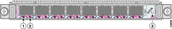
The 2-Port and 4-Port Clear Channel T3/E3 SPA has three types of LEDs: two LEDs for each port on the SPA, and one STATUS LED, as shown in Figure 2-1.
Figure 2-1 4-Port Clear Channel T3/E3 SPA Faceplate

|
|
|
||
|
|
|
||
|
|
|
Table 2-3 describes the 2-Port and 4-Port Clear Channel T3/E3 SPA LEDs.
|
|
|
|
|
|---|---|---|---|
Port is enabled by software, and there is a valid E3 or T3 signal without any alarms. |
|||
Port is enabled by software, and there is at least one alarm. |
|||
2-Port and 4-Port Clear Channel T3/E3 SPA Interface Specifications
The framer processes incoming and outgoing T3 (cbit, m13/m23, and unframe) and E3 (g751, g832, and unframe) frames. The framer operates at T3/E3 line rates (44.736 /34.368 Mbps) depending on the mode in which it is configured.
Packet data is transported with a user-configurable encapsulation (such as Point-to-Point Protocol [PPP] or High-Level Data Link Control [HDLC]), and is mapped to T3 and E3 frames. The encapsulations add transport overhead to the packet of data frames before transporting, and are stripped when a packet is transported to the far end.
The T3/E3 SPA interface is compliant with ANSI and Telco standards. The interface also provides support for Management Information Base (MIB) RFC 2496 and T1.231.
2-Port and 4-Port Clear Channel T3/E3 SPA Cables and Connectors
The interface connectors on the 2-Port and 4-Port Clear Channel T3/E3 SPA are 75-ohm coaxial Siemax types, with one connector and cable for transmit (TX) and one for receive (RX).
The following cables can be used with the 2-Port and 4-Port Clear Channel T3/E3 SPA. The cables have BNC connectors on one end and the Siemax connectors on the other. If similar SPAs are connected back-to-back, both ends of cable will be Siemax.
- CAB-T3E3-RF-BNC-M (T3 or E3 Cable, 1.0/2.3 RF to BNC-Male, 10 feet)
- CAB-T3E3-RF-BNC-F (T3 or E3 Cable, 1.0/2.3 RF to BNC-Female, 10 feet)
- CAB-T3E3-RF-OPEN (T3 or E3 Cable, 1.0/2.3 RF to BNC-Open end, 10 feet)
Note![]() The Cisco cable part numbers are 72-4124-01 (with male BNC end) and 72-4131-01 (with female BNC end).
The Cisco cable part numbers are 72-4124-01 (with male BNC end) and 72-4131-01 (with female BNC end).
Figure 2-1 shows the connectors on the 4-Port Clear Channel T3/E3 SPA, and Table 2-4 describes the signal descriptions for these connectors.
2-Port and 4-Port Channelized T3 to DS0 SPA Overview
The following sections describe the 2-Port and 4-Port Channelized T3 SPA:
- 2-Port and 4-Port Channelized T3 SPA LEDs
- 2-Port and 4-Port Channelized T3 SPA Interface Specifications
- 2-Port and 4-Port Channelized T3 SPA Cables and Connectors
2-Port and 4-Port Channelized T3 SPA LEDs
The 2-Port and 4-Port Channelized T3 SPA has three types of LEDs. There are two LEDs for each port on the SPA, and one STATUS LED. Figure 2-2 shows an example of these LEDs on a 4-Port Channelized T3 SPA.
Figure 2-2 4-Port Channelized T3 SPA Faceplate

|
|
|
||
|
|
|
||
|
|
|
The 2-Port and 4-Port Channelized T3 SPA LEDs are described in Table 2-5 .
|
|
|
|
|
|---|---|---|---|
Port is enabled by software, and there is a valid E3 or T3 signal without any alarms. |
|||
Port is enabled by software, and there is at least one alarm. |
|||
2-Port and 4-Port Channelized T3 SPA Interface Specifications
The framer processes incoming and outgoing T3 frames (cbit, m13/m23, and unframe) and E3 (g751, g832) frames. The framer operates at T3/E3 line rates (44.2 44.736/34.368 Mbps) depending on the mode in which it is configured.
Packet data is transported with a user-configurable encapsulation (such as Point-to-Point Protocol [PPP] or High-Level Data Link Control [HDLC]), and is mapped to T3 and E3 frames. The encapsulations add transport overhead to the packet of data frames before transporting, and are stripped when a packet is transported to the far end.
The T3/E3 SPA interface is compliant with ANSI and Telco standards. The interface also provides support for Management Information Base (MIB) RFC 2495, RFC 2496, and T1.231.
Note![]() The 2-Port and 4-Port Channelized T3 SPA supports Frame Relay Fragmentation (FRF.12) and Multilink Fame Relay (MFR) features for Cisco IOS XR Software Release 3.6.0 and later releases.
The 2-Port and 4-Port Channelized T3 SPA supports Frame Relay Fragmentation (FRF.12) and Multilink Fame Relay (MFR) features for Cisco IOS XR Software Release 3.6.0 and later releases.
2-Port and 4-Port Channelized T3 SPA Cables and Connectors
The interface connectors on the 2-Port and 4-Port Channelized T3 SPA are 75-ohm coaxial Siemax types, with one connector and cable for transmit (TX) and one for receive (RX).
The following cables can be used with the 2-Port and 4-Port Channelized T3 SPA. The cables have BNC connectors on one end and the Siemax connectors on the other.
- CAB-T3E3-RF-BNC-M (T3 or E3 Cable, 1.0/2.3 RF to BNC-Male, 10 feet)
- CAB-T3E3-RF-BNC-F (T3 or E3 Cable, 1.0/2.3 RF to BNC-Female, 10 feet)
- CAB-T3E3-RF-OPEN (T3 or E3 Cable, 1.0/2.3 RF to BNC-Open end, 10 feet)
Note![]() The Cisco cable part numbers are 72-4124-01 (with Male BNC end) and 72-4131-01 (with Female BNC end).
The Cisco cable part numbers are 72-4124-01 (with Male BNC end) and 72-4131-01 (with Female BNC end).
Figure 2-2 shows the Siemax connectors on the 2-Port and 4-Port Channelized T3 SPA, and Table 2-6 provides the signal descriptions for these connectors.
8-Port Channelized T1/E1 SPA Overview
The following sections describe the 8-Port Channelized T1/E1 SPA:
- 8-Port Channelized T1/E1 SPA LEDs
- XFP Connections
- 8-Port Channelized T1/E1 SPA Cables, Connectors, and Pinouts
8-Port Channelized T1/E1 SPA LEDs
The 8-Port Channelized T1/E1 SPA has three types of LEDs. There are two LEDs for each port on the SPA, and one STATUS LED as shown in Figure 2-3.
Figure 2-3 8-Port Channelized T1/E1 SPA Faceplate

|
|
|
||
|
|
|
The 8-Port Channelized T1/E1 SPA LEDs are described in Table 2-7 .
|
|
|
|
|
|---|---|---|---|
Port is enabled by software, and there is a valid T1 or E1 signal without any alarms. |
|||
Port is enabled by software, and there is at least one alarm. |
|||
8-Port Channelized T1/E1 SPA Interface Specifications
The E1 interface on the 8-Port Channelized T1/E1 SPA uses RJ-48c receptacles for E1 (120-Ohm) cables with RJ-45 connectors. You can use all ports simultaneously. Each E1 connection supports interfaces that meet G.703 standards. The RJ-45 connection does not require an external transceiver. The E1 ports are E1 interfaces that use 120-ohm shielded twisted pair (STP) cables.

Warning![]() Shielded twisted pair (STP) T1/E1 cables must be used to comply with EN55022/CISPR22 Class A emissions requirements. For revisions 73-8358-05 through 73-8358-08 Shielded Twisted pair (STP) T1/E1 cables must be used to comply with FCC Class A emissions requirements.
Shielded twisted pair (STP) T1/E1 cables must be used to comply with EN55022/CISPR22 Class A emissions requirements. For revisions 73-8358-05 through 73-8358-08 Shielded Twisted pair (STP) T1/E1 cables must be used to comply with FCC Class A emissions requirements.
8-Port Channelized T1/E1 SPA Cables, Connectors, and Pinouts
Figure 2-4 shows an RJ-45 connector.
Note![]() The terms RJ-45 and RJ-48c are sometimes used interchangeably. The RJ-48c is the jack or receptacle; the RJ-45 is the connector.
The terms RJ-45 and RJ-48c are sometimes used interchangeably. The RJ-48c is the jack or receptacle; the RJ-45 is the connector.

Table 2-8 describes the signals and connector pinouts for RJ-45 cable connectors.
|
|
|
|
|---|---|---|
8 Port FastEthernet SPA Overview
The following sections describe the 8-Port FastEthernet SPA:
8-Port FastEthernet SPA LEDs
The 8-Port FastEthernet SPA has two types of LEDs: an A/L LED for each individual port and a STATUS LED for the SPA, as shown in Figure 2-5.
Figure 2-5 8-Port FastEthernet SPA Faceplate

|
|
|
Table 2-9 describes the 8-Port FastEthernet SPA LEDs.
|
|
|
|
|
|---|---|---|---|
| Port Number |
|||
|
2.In this case, port number refers to the numbered LEDs on the 8-Port FastEthernet SPA (0, 1, 2, 3, 4, 5, 6 or 7). Each LED number on the 8-Port FastEthernet SPA references a port on the SPA. |
8-Port FastEthernet SPA Cables, Connectors, and Pinouts
The interface connectors on the 8-Port FastEthernet SPA are eight individual RJ-45 receptacles. You can use all eight interface connectors simultaneously. Each connection supports IEEE 802.3 and Ethernet 10/100BASE-T interfaces compliant with appropriate standards. Cisco Systems does not supply Category 5 unshielded twisted-pair (UTP) RJ-45 cables; these cables are available commercially.
Figure 2-6 shows the RJ-45 connector.
Figure 2-6 RJ-45 Connections, Plug, and Receptacle

Table 2-10 lists the pinouts and signals for the RJ-45 connector.
|
|
|
|---|---|
Note![]() Referring to the RJ-45 pinout in Table 2-10, proper common-mode line terminations should be used for the unused Category 5 UTP cable pairs 4/5 and 7/8. Common-mode termination reduces the contributions to electromagnetic interference (EMI) and susceptibility to common-mode sources. Wire pairs 4/5 and 7/8 are actively terminated in the RJ-45 port circuitry in the 8-Port FastEthernet SPA.
Referring to the RJ-45 pinout in Table 2-10, proper common-mode line terminations should be used for the unused Category 5 UTP cable pairs 4/5 and 7/8. Common-mode termination reduces the contributions to electromagnetic interference (EMI) and susceptibility to common-mode sources. Wire pairs 4/5 and 7/8 are actively terminated in the RJ-45 port circuitry in the 8-Port FastEthernet SPA.
The 8-Port FastEthernet SPA supports automatic MDI/MDIX crossover at all speeds of operation allowing the SPA to work with straight-through and crossover Ethernet cables. Depending on your RJ-45 interface cabling requirements, use the pinouts in Figure 2-7 and Figure 2-8.
Figure 2-7 Straight-Through Cable Pinout, RJ-45 Connection to a Hub or Repeater
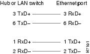
Figure 2-8 Crossover Cable Pinout, RJ-45 Connections Between Routers

1 Port 10-Gigabit Ethernet SPA Overview
The following sections describe the 1-Port 10-Gigabit Ethernet SPA:
- 1-Port 10-Gigabit Ethernet SPA LEDs
- 1-Port 10-Gigabit Ethernet SPA XFP Optical Transceiver Modules, Connectors, and Cables
1-Port 10-Gigabit Ethernet SPA LEDs
The 1-Port 10-Gigabit Ethernet SPA has two LEDs, an ACTIVE/LINK LED for the port and a STATUS LED, as shown in Figure 2-9.
Figure 2-9 1-Port 10-Gigabit Ethernet SPA Faceplate

|
|
|
Table 2-11 describes the 1-Port 10-Gigabit Ethernet SPA LEDs.
|
|
|
|
|
|---|---|---|---|
1-Port 10-Gigabit Ethernet SPA XFP Optical Transceiver Modules, Connectors, and Cables
The 1-Port 10-Gigabit Ethernet SPA supports the following types of optical transceiver modules:
- Single-mode short-reach (SR) XFP module—XFP-10GLR-OC192SR
- Single-mode intermediate-reach (IR) XFP module—XFP-10GER-OC192IR
- Single-mode very-long-reach (ZR) XFP module—XFP-10GER-OC192LR
- Multi-mode short reach (SR) XFP module—XFP-10G-MM-SR
Cisco Systems qualifies the optics that are approved for use with its SPAs. As of Cisco IOS XR Release 3.4.1, the above-listed small form-factor pluggable (XFPs) are the only optical transceiver modules qualified for use.
Use a single-mode optical fiber that has a modal-field diameter of 8.7 ±0.5 microns (nominal diameter is approximately 10/125 microns) to connect your router to a network.
Figure 2-10 shows the cable type for use with the XFP optical transceiver module on the 1-Port 10-Gigabit Ethernet SPA.
Figure 2-10 LC-Type Cable for the XFP Optical Transceiver Modules
Note![]() The 40-pin connector on the 1-Port 10-Gigabit Ethernet SPA is used for resilient packet ring (RPR) connections. This feature is not supported in Cisco IOS XR Release 4.3.0.
The 40-pin connector on the 1-Port 10-Gigabit Ethernet SPA is used for resilient packet ring (RPR) connections. This feature is not supported in Cisco IOS XR Release 4.3.0.
XFP Connections
The 10GLR, 10GER, and 10GZR XFP modules include an optical transmitter and receiver pair integrated with Clock and Data Recovery (CDR) integrated circuits. The XFP modules provide high-speed serial links at the rate of 10.3125 Gbps (10 Gigabit Ethernet) on single-mode fiber (SMF). The transmit side recovers and retimes the 10-Gbps serial data and passes it to a laser driver. The laser driver biases and modulates a 1310-nm, 850 nm or 155-nm laser, enabling data transmission over SMF through an LC connector. The receive side recovers and retimes the 10-Gbps optical data stream from a photo detector transimpedance amplifier and passes it to an output driver.
See the label on the XFP module for technology type and model. Figure 2-11 shows an XFP module and Table 2-12 shows the XFP module specifications.

XFP Port Cabling Specifications
Table 2-13 shows the port cabling specifications for an XFP module.
|
|
|
|
|---|---|---|
2-Port Gigabit Ethernet SPA Overview
The following sections describe the version 1 and version 2 of the 2-Port Gigabit Ethernet SPA:
- 2-Port Gigabit Ethernet SPA LEDs
- 2-Port Gigabit Ethernet SPA (Version 2) LEDs
- SFP Module Cabling and Connection Equipment
2-Port Gigabit Ethernet SPA LEDs
The 2-Port Gigabit Ethernet SPA has two types of LEDs: an A/L LED for each port and a STATUS LED, as shown in Figure 2-12.
Figure 2-12 2-Port Gigabit Ethernet SPA Faceplate

|
|
|
||
|
|
|
Table 2-14 describes the 2-Port Gigabit Ethernet SPA LEDs.
|
|
|
|
|
|---|---|---|---|
2-Port Gigabit Ethernet SPA (Version 2) LEDs
The 2-Port Gigabit Ethernet SPA (Version 2) has two types of LEDs: an A/L LED for each SFP port and a STATUS LED, as shown in Figure 2-13.
Figure 2-13 2-Port Gigabit Ethernet SPA (Version 2) Faceplate

Table 2-15 describes the 2-Port Gigabit Ethernet SPA (Version 2) LEDs.
|
|
|
|
|
|
|
|
|---|---|---|---|
The valid configuration of the SFP ports for the 2-Port Gigabit Ethernet SPA (Version 2) is Port 0 (SFP) and Port 1 (SFP), or any single port.
Note![]() The 2-Port Gigabit Ethernet SPA has two RJ-45 ports. However, these RJ-45 ports are not supported by the Cisco XR 12000 Series Router.
The 2-Port Gigabit Ethernet SPA has two RJ-45 ports. However, these RJ-45 ports are not supported by the Cisco XR 12000 Series Router.
2-Port Gigabit Ethernet SPA Cables and Connectors
The interface connectors on the 2-Port Gigabit Ethernet SPA are two individual fiber-optic receivers that support SFP modules. Each port can send and receive traffic using the optical fiber connections.
SFP Module Connections
The small form-factor pluggable (SFP) module is an input/output (I/O) device that plugs into the Gigabit Ethernet ports on the 2-Port Gigabit Ethernet SPA, linking the port with a fiber-optic network.
Note![]() The 2-Port Gigabit Ethernet SPA will only accept the SFP modules listed as supported in this document. An SFP module check is run every time an SFP module is inserted into the 2-Port Gigabit Ethernet SPA and only SFP modules that pass this check will be usable by the 2-Port Gigabit Ethernet SPA.
The 2-Port Gigabit Ethernet SPA will only accept the SFP modules listed as supported in this document. An SFP module check is run every time an SFP module is inserted into the 2-Port Gigabit Ethernet SPA and only SFP modules that pass this check will be usable by the 2-Port Gigabit Ethernet SPA.
SFP modules exist for technologies other than Gigabit Ethernet and for products other than the 2-Port Gigabit Ethernet SPA. However, the information in this document pertains only to SFP modules that plug into the 2-Port Gigabit Ethernet SPA ports.
The SFP module has a receiver port (RX) and a transmitter port (TX) that compose one optical interface. Table 2-16 and Table 2-17 provide SFP module information and specifications.
SFP-GE-S Modules
The 1000BASE-SX (short wavelength) module operates on standard multimode fiber-optic link spans of up to 500 m on 50/125um MMF and 300 m on 62.5/125um MMF.
SFP-GE-L Modules
The 1000BASE-LX/LH (long wavelength/long haul) module interfaces fully comply with the
IEEE 802.3z 1000BASE-LX standard. However, their higher optical quality allows them to reach 6.2 miles (10 km) over single-mode fiber (SMF) versus the 3.1 miles (5 km) specified in the standard.
SFP-GE-Z Modules
The 1000BASE-ZX (extended wavelength) module operates on ordinary single-mode fiber-optic link spans of up to 49.7 miles (80 km). Link spans of up to 62.1 miles (100 km) are possible using premium single-mode fiber or dispersion-shifted single-mode fiber (premium single-mode fiber has a lower attenuation per unit length than ordinary single-mode fiber; dispersion-shifted single-mode fiber has both lower attenuation and less dispersion).
The 1000BASE-ZX module must be coupled to single-mode fiber-optic cable, which is the type of cable typically used in long-haul telecommunications applications. The 1000BASE-ZX module will not operate correctly when coupled to multimode fiber, and it is not intended to be used in environments where multimode fiber is frequently used (for example, building backbones, or horizontal cabling).
The 1000BASE-ZX module is intended to be used as a Physical Medium Dependent (PMD) component for Gigabit Ethernet interfaces found on various switch and router products. It operates at a signaling rate of 1250 Mbaud, transmitting and receiving 8B/10B encoded data.
When shorter lengths of single-mode fiber are used, it may be necessary to insert an in-line optical attenuator in the link to avoid overloading the receiver.
- Insert a 10-dB in-line optical attenuator between the fiber-optic cable plant and the receiving port on the 1000BASE-ZX module at each end of the link whenever the fiber-optic cable span is less than 15.5 miles (25 km).
- Insert a 5-dB in-line optical attenuator between the fiber-optic cable plant and the receiving port on the 1000BASE-ZX module at each end of the link whenever the fiber-optic cable span is equal to or greater than 15.5 miles (25 km) but less than 31 miles (50 km).
SFP-GE-T Modules
The SFP-GE-T (1000BASE-T copper SFP module) provides full-duplex Gigabit Ethernet connectivity to high-end workstations and between wiring closets over an existing copper network infrastructure. The SFP-GE-T maximum cabling distance is 328 feet (100 m).
SFP Module Cabling and Connection Equipment
Table 2-18 provides cabling specifications for the SFP modules that can be installed on the 2-Port Gigabit Ethernet SPA. Note that all SFP ports have LC-type connectors.
The minimum cable distance for the SFP-GE-S is 6.5 feet (2 m), and the minimum link distance for the SFP-GE-Z is 6.2 miles (10 km) with an 8-dB attenuator installed at each end of the link. Without attenuators, the minimum link distance for the SFP-GE-Z is 24.9 miles (40 km).
|
|
|
|
|
|
Cable Distance |
|---|---|---|---|---|---|
| MMF3 |
|||||
| MMF4 and SMF |
|||||
SMF5 |
|||||
Note![]() The 1000BASE-ZX SFP modules provide an optical power budget of 21.5 dB. You should measure your cable plant with an optical loss test set to verify that the optical loss of the cable plant (including connectors and splices) is less than or equal to 21.5 dB. The optical loss measurement must be performed with a 1550-nm light source.
The 1000BASE-ZX SFP modules provide an optical power budget of 21.5 dB. You should measure your cable plant with an optical loss test set to verify that the optical loss of the cable plant (including connectors and splices) is less than or equal to 21.5 dB. The optical loss measurement must be performed with a 1550-nm light source.
5-Port Gigabit Ethernet SPA Overview
The following sections describe the 5-Port Gigabit Ethernet SPA:
5-Port Gigabit Ethernet SPA LEDs
The 5-Port Gigabit Ethernet SPA has two types of LEDs: an A/L LED for each individual port and a STATUS LED for the SPA, as shown in Figure 2-14.
Figure 2-14 5-Port Gigabit Ethernet SPA Faceplate
|
|
|
Table 2-19 describes the 5-Port Gigabit Ethernet SPA LEDs.
|
|
|
|
|
|---|---|---|---|
5-Port Gigabit Ethernet SPA Cables and Connectors
The 5-Port Gigabit Ethernet SPA has five electrical connectors that support SFP modules. Each port can send and receive traffic using cabling appropriate for the SFP module inserted.
SFP Module Connections
The small form-factor pluggable (SFP) module is an input/output (I/O) device that plugs into the Gigabit Ethernet ports on the 5-Port Gigabit Ethernet SPA, linking the port with a fiber-optic network.
Note![]() The 5-Port Gigabit Ethernet SPA accepts only the SFP modules listed as supported in this document. An SFP module check is run every time an SFP module is inserted into the 5-Port Gigabit Ethernet SPA, and only SFP modules that pass this check can be used by the 5-Port Gigabit Ethernet SPA.
The 5-Port Gigabit Ethernet SPA accepts only the SFP modules listed as supported in this document. An SFP module check is run every time an SFP module is inserted into the 5-Port Gigabit Ethernet SPA, and only SFP modules that pass this check can be used by the 5-Port Gigabit Ethernet SPA.
SFP modules exist for technologies other than Gigabit Ethernet and for products other than the 5-Port Gigabit Ethernet SPA. However, the information in this document pertains only to SFP modules that plug into the 5-Port Gigabit Ethernet SPA ports.
The SFP module has a receiver port (RX) and a transmitter port (TX) that compose one optical interface. Table 2-20 and Table 2-21 provide SFP module information and specifications.
SFP-GE-S Modules
The 1000BASE-SX (short-wavelength) module operates on standard multimode fiber-optic link spans of up to 500 m on 50/125um multimode fiber (MMF) and 300 m on 62.5/125um MMF.
SFP-GE-L Modules
The 1000BASE-LX/LH (long-wavelength/long-haul) module interfaces fully comply with the
IEEE 802.3z 1000BASE-LX standard. However, their higher optical quality allows them to reach 6.2 miles (10 km) over single-mode fiber (SMF) versus the 3.1 miles (5 km) specified in the standard.
SFP-GE-Z Modules
The 1000BASE-ZX (extended wavelength) module operates on ordinary single-mode fiber-optic link spans of up to 49.7 miles (80 km). Link spans of up to 62.1 miles (100 km) are possible using premium single-mode fiber or dispersion-shifted single-mode fiber. (Premium single-mode fiber has a lower attenuation per unit length than ordinary single-mode fiber; dispersion-shifted single-mode fiber has both lower attenuation and less dispersion.)
The 1000BASE-ZX module must be coupled to single-mode fiber-optic cable, which is the type of cable typically used in long-haul telecommunications applications. The 1000BASE-ZX module does not operate correctly when coupled to multimode fiber, and it is not intended to be used in environments in which multimode fiber is frequently used (for example, building backbones or horizontal cabling).
The 1000BASE-ZX module is intended to be used as a Physical Medium Dependent (PMD) component for Gigabit Ethernet interfaces found on various switch and router products. It operates at a signaling rate of 1250 Mbaud, transmitting and receiving 8B/10B encoded data.
When shorter lengths of single-mode fiber are used, it may be necessary to insert an inline optical attenuator in the link to avoid overloading the receiver. Use the following guidelines:
- Insert a 10-dB inline optical attenuator between the fiber-optic cable plant and the receiving port on the 1000BASE-ZX module at each end of the link whenever the fiber-optic cable span is less than 15.5 miles (25 km).
- Insert a 5-dB inline optical attenuator between the fiber-optic cable plant and the receiving port on the 1000BASE-ZX module at each end of the link whenever the fiber-optic cable span is equal to or greater than 15.5 miles (25 km) but less than 31 miles (50 km).
SFP-GE-T Modules
The SFP-GE-T (1000BASE-T copper SFP module) provides full-duplex Gigabit Ethernet connectivity to high-end workstations and between wiring closets over an existing copper network infrastructure. The SFP-GE-T maximum cabling distance is 328 feet (100 m).
SFP Module Cabling and Connection Equipment
Table 2-22 provides cabling specifications for the SFP modules that can be installed on the 5-Port Gigabit Ethernet SPA. Note that all SFP ports have LC-type connectors.
The minimum cable distance for the SFP-GE-S is 6.5 feet (2 m), and the minimum link distance for the SFP-GE-Z is 6.2 miles (10 km) with an 8-dB attenuator installed at each end of the link. Without attenuators, the minimum link distance for the SFP-GE-Z is 24.9 miles (40 km).
|
|
|
|
|
|
Cable Distance |
|---|---|---|---|---|---|
| MMF6 |
|||||
| MMF7 and SMF |
|||||
SMF8 |
|||||
Note![]() The 1000BASE-ZX SFP modules provide an optical power budget of 21.5 dB. You should measure your cable plant with an optical loss test set to verify that the optical loss of the cable plant (including connectors and splices) is less than or equal to 21.5 dB. The optical loss measurement must be performed with a 1550-nm light source.
The 1000BASE-ZX SFP modules provide an optical power budget of 21.5 dB. You should measure your cable plant with an optical loss test set to verify that the optical loss of the cable plant (including connectors and splices) is less than or equal to 21.5 dB. The optical loss measurement must be performed with a 1550-nm light source.
10-Port Gigabit Ethernet SPA Overview
The following sections describe the 10-Port Gigabit Ethernet SPA:
10-Port Gigabit Ethernet SPA LEDs
The 10-Port Gigabit Ethernet SPA has two types of LEDs: an A/L LED for each individual port and a STATUS LED for the SPA, as shown in Figure 2-15.
Figure 2-15 10-Port Gigabit Ethernet SPA Faceplate

|
|
|
Table 2-23 describes the 10-Port Gigabit Ethernet SPA LEDs.
|
|
|
|
|
|---|---|---|---|
10-Port Gigabit Ethernet SPA Cables and Connectors
The 10-Port Gigabit Ethernet SPA has ten electrical connectors that support SFP modules. Each port can send and receive traffic using cabling appropriate for the SFP module inserted.
SFP Module Connections
The small form-factor pluggable (SFP) module is an input/output (I/O) device that plugs into the Gigabit Ethernet optical slots on the 10-Port Gigabit Ethernet SPA, linking the port with a 1000BASE-X fiber-optic network.
Note![]() The 10-Port Gigabit Ethernet SPA accepts only the SFP modules listed as supported in this document. An SFP module check is run every time an SFP is inserted into the 10-Port Gigabit Ethernet SPA, and only SFP modules that pass this check can be used by the 10-Port Gigabit Ethernet SPA.
The 10-Port Gigabit Ethernet SPA accepts only the SFP modules listed as supported in this document. An SFP module check is run every time an SFP is inserted into the 10-Port Gigabit Ethernet SPA, and only SFP modules that pass this check can be used by the 10-Port Gigabit Ethernet SPA.
SFP modules exist for technologies other than Gigabit Ethernet and for products other than the 10-Port Gigabit Ethernet SPA. However, the information in this document pertains only to SFP modules that plug into the 10-Port Gigabit Ethernet SPA ports.
The SFP module has a receiver port (RX) and a transmitter port (TX) that compose one optical interface. Table 2-24 and Table 2-25 provide SFP information and specifications.
SFP-GE-S Modules
The 1000BASE-SX (short-wavelength) module operates on standard multimode fiber-optic link spans of up to 500 m on 50/125um multimode fiber (MMF) and 300 m on 62.5/125um MMF.
SFP-GE-L Modules
The 1000BASE-LX/LH (long-wavelength/long-haul) module interfaces fully comply with the
IEEE 802.3z 1000BASE-LX standard. However, their higher optical quality allows them to reach 6.2 miles (10 km) over single-mode fiber (SMF) versus the 3.1 miles (5 km) specified in the standard.
SFP-GE-Z Modules
The 1000BASE-ZX (extended-wavelength) module operates on ordinary single-mode fiber-optic link spans of up to 49.7 miles (80 km). Link spans of up to 62.1 miles (100 km) are possible using premium single-mode fiber or dispersion-shifted single-mode fiber. (Premium single-mode fiber has a lower attenuation per unit length than ordinary single-mode fiber; dispersion-shifted single-mode fiber has both lower attenuation and less dispersion.)
The 1000BASE-ZX module must be coupled to single-mode fiber-optic cable, which is the type of cable typically used in long-haul telecommunications applications. The 1000BASE-ZX module does not operate correctly when coupled to multimode fiber, and it is not intended to be used in environments in which multimode fiber is frequently used (for example, building backbones or horizontal cabling).
The 1000BASE-ZX module is intended to be used as a Physical Medium Dependent (PMD) component for Gigabit Ethernet interfaces found on various switch and router products. It operates at a signaling rate of 1250 Mbaud, transmitting and receiving 8B/10B encoded data.
When shorter lengths of single-mode fiber are used, it may be necessary to insert an inline optical attenuator in the link to avoid overloading the receiver. Use the following guidelines:
- Insert a 10-dB inline optical attenuator between the fiber-optic cable plant and the receiving port on the 1000BASE-ZX module at each end of the link whenever the fiber-optic cable span is less than 15.5 miles (25 km).
- Insert a 5-dB inline optical attenuator between the fiber-optic cable plant and the receiving port on the 1000BASE-ZX module at each end of the link whenever the fiber-optic cable span is equal to or greater than 15.5 miles (25 km) but less than 31 miles (50 km).
SFP Module Cabling and Connection Equipment
Table 2-26 provides cabling specifications for the SFP modules that can be installed on the 10-Port Gigabit Ethernet SPA. Note that all SFP ports have LC-type connectors.
The minimum cable distance for the SFP-GE-S is 6.5 feet (2 m), and the minimum link distance for the SFP-GE-Z is 6.2 miles (10 km) with an 8-dB attenuator installed at each end of the link. Without attenuators, the minimum link distance for the SFP-GE-Z is 24.9 miles (40 km).
|
|
|
|
|
|
Cable Distance |
|---|---|---|---|---|---|
| MMF9 |
|||||
SMF10 |
|
|
Note![]() The 1000BASE-ZX SFP modules provide an optical power budget of 21.5 dB. You should measure your cable plant with an optical loss test set to verify that the optical loss of the cable plant (including connectors and splices) is less than or equal to 21.5 dB. The optical loss measurement must be performed with a 1550-nm light source.
The 1000BASE-ZX SFP modules provide an optical power budget of 21.5 dB. You should measure your cable plant with an optical loss test set to verify that the optical loss of the cable plant (including connectors and splices) is less than or equal to 21.5 dB. The optical loss measurement must be performed with a 1550-nm light source.
1-Port Channelized STM-1/OC-3 SPA Overview
The following sections describe the 1-Port Channelized STM-1/OC-3 SPA:
- 1-Port Channelized STM-1/OC-3 SPA LEDs
- 1-Port Channelized STM-1/OC-3 SPA Interface Specifications
- 1-Port Channelized STM-1/OC-3 SPA Cables and Connectors
1-Port Channelized STM-1/OC-3 SPA LEDs
The 1-Port Channelized STM-1/OC-3 SPA has two types of LEDs: an A/L LED for each port and a STATUS LED, as shown in Figure 2-16.
Figure 2-16 1-Port Channelized STM-1/OC-3 SPA Faceplate

|
|
|
||
|
|
|
The 1-Port Channelized STM-1/OC-3 SPALEDs are described in Table 2-27 .
|
|
|
|
|
|---|---|---|---|
Port is enabled by software, and there is a valid T3 signal without any alarms. |
|||
Port is enabled by software, and there is at least one alarm. |
|||
1-Port Channelized STM-1/OC-3 SPA Interface Specifications
The framer processes incoming and outgoing SONET or SDH frames. The framer operates at OC-3/STM-1 line rates (155.52 Mbps).
Packet data is transported with a user-configured encapsulation (such as Point-to-Point Protocol [PPP]) and is mapped into the STS-3/STM-1 frame.
The 1-Port Channelized STM-1/OC-3 SPA interface is compliant with RFC 1619, PPP over SONET/SDH, and RFC 1662, PPP in HDLC-like Framing. The 1-Port Channelized STM-1/OC-3 SPA also provides support for SNMP v1 agent (RFC 1155–1157), and Management Information Base (MIB) II (RFC 1213).
Note![]() The 1-Port Channelized STM-1/OC-3 SPA supports Frame Relay Fragmentation (FRF.12) and Multilink Fame Relay (MFR) features for Cisco IOS XR Software Release 3.6.0 and later releases.
The 1-Port Channelized STM-1/OC-3 SPA supports Frame Relay Fragmentation (FRF.12) and Multilink Fame Relay (MFR) features for Cisco IOS XR Software Release 3.6.0 and later releases.
1-Port Channelized STM-1/OC-3 SPA Cables and Connectors
The 1-Port Channelized STM-1/OC-3 SPA uses a small form-factor pluggable (SFP) optical transceiver module installed in each port for SONET and SDH single-mode and multimode optical fiber connection (see Figure 2-17).

The SFP optical transceiver modules used with the 1-Port Channelized STM-1/OC-3 SPA provide the following optical fiber options:
Use a multimode optical fiber that has a core/cladding diameter of 62.5/125 microns.
Use a single-mode optical fiber that has a modal-field diameter of 8.7 ±0.5 microns. (Nominal diameter is approximately 10/125 microns.)
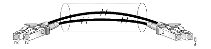
For single-mode and multimode optical fiber connections, you can use either a duplex LC-type cable (see Figure 2-18) or two simplex LC-type cables, one for transmit (TX) and one for receive (RX).
Use single-mode (for intermediate- or long-reach configurations) or multimode optical fiber cable to connect your router to a network or to connect two 1-Port Channelized STM-1/OC-3 SPA-equipped routers back to back.
Long-range SFP optical transceiver modules (for long-reach configurations) cannot be connected back-to-back without using an attenuator between the two of them.
1-Port Channelized STM-4/OC-12 SPA Overview
The following sections describe the 1-Port Channelized STM-4/OC-12 SPA:
- 1-Port Channelized STM-4/OC-12 SPA LEDs
- 1-Port Channelized STM-4/OC-12 SPA Interface Specifications
- 1-Port Channelized STM-4/OC-12 SPA Cables and Connectors
1-Port Channelized STM-4/OC-12 SPA LEDs
The 1-Port Channelized STM-4/OC-12 SPA has two types of LEDs: an A/L LED for each port and a STATUS LED, as shown in Figure 2-19.
Figure 2-19 1-Port Channelized STM-4/OC-12 SPA Faceplate

|
|
|
||
|
|
|
The 1-Port Channelized STM-4/OC-12 SPALEDs are described in Table 2-28 .
|
|
|
|
|
|---|---|---|---|
Port is enabled by software, and there is a valid T3 signal without any alarms. |
|||
Port is enabled by software, and there is at least one alarm. |
|||
1-Port Channelized STM-4/OC-12 SPA Interface Specifications
The framer processes incoming and outgoing SONET or SDH frames. The framer operates at OC-12/STM-4 line rates (622.08 Mbps).
Packet data is transported with a user-configured encapsulation (such as Point-to-Point Protocol [PPP]) and is mapped into the STS-12/STM-4 frame.
The 1-Port Channelized STM-4/OC-12 SPA interface is compliant with RFC 1619, PPP over SONET/SDH, and RFC 1662, PPP in HDLC-like Framing. The 1-Port Channelized STM-4/OC-12 SPA also provides support for SNMP v1 agent (RFC 1155–1157), and Management Information Base (MIB) II (RFC 1213).
Note![]() For Cisco IOS XR Software Release 3.8.0 and beyond, the 1-Port Channelized STM-4/OC-12 SPA supports Frame Relay Fragmentation (FRF.12) to achieve fragmentation of data packets and interleaving of voice packets. FRF.12 provides a method to fragment low-priority packets and interleave high-priority packets in between the low-priority fragments to provide less delay or jitter for high-priority traffic like voice and video.
For Cisco IOS XR Software Release 3.8.0 and beyond, the 1-Port Channelized STM-4/OC-12 SPA supports Frame Relay Fragmentation (FRF.12) to achieve fragmentation of data packets and interleaving of voice packets. FRF.12 provides a method to fragment low-priority packets and interleave high-priority packets in between the low-priority fragments to provide less delay or jitter for high-priority traffic like voice and video.
Note![]() For Cisco IOS XR Software Release 3.8.0 and beyond, the 1-Port Channelized STM-4/OC-12 SPA supports Multilink Frame Relay (MFR) feature. MFR provides a mechanism for aggregating multiple serial links into a bundle to provide greater bandwidth, load balancing between links, and improved service availability by protecting against single point link failures.
For Cisco IOS XR Software Release 3.8.0 and beyond, the 1-Port Channelized STM-4/OC-12 SPA supports Multilink Frame Relay (MFR) feature. MFR provides a mechanism for aggregating multiple serial links into a bundle to provide greater bandwidth, load balancing between links, and improved service availability by protecting against single point link failures.
1-Port Channelized STM-4/OC-12 SPA Cables and Connectors
The 1-Port Channelized STM-4/OC-12 SPA uses a small form-factor pluggable (SFP) optical transceiver module installed in each port for SONET and SDH single-mode and multimode optical fiber connection (see Figure 2-20).
The SFP optical transceiver modules used with the 1-Port Channelized STM-4/OC-12 SPA provide the following optical fiber options:
Use a multimode optical fiber that has a core/cladding diameter of 62.5/125 microns.
Use a single-mode optical fiber that has a modal-field diameter of 8.7 ±0.5 microns. (Nominal diameter is approximately 10/125 microns.)
For single-mode and multimode optical fiber connections, you can use either a duplex LC-type cable (see Figure 2-21) or two simplex LC-type cables, one for transmit (TX) and one for receive (RX).
Use single-mode (for intermediate- or long-reach configurations) or multimode optical fiber cable to connect your router to a network or to connect two 1-Port Channelized STM-4/OC-12 SPA-equipped routers back to back.
Long-range SFP optical transceiver modules (for long-reach configurations) cannot be connected back-to-back without using an attenuator between the two of them.
1-Port Channelized STM-16/OC-48 SPA Overview
The following sections describe the 1-Port Channelized STM-4/OC-12 SPA:
- 1-Port Channelized STM-16/OC-48 SPA LEDs
- 1-Port Channelized STM-16/OC-48 SPA Interface Specifications
- 1-Port Channelized STM-16/OC-48 SPA Cables and Connectors
1-Port Channelized STM-16/OC-48 SPA LEDs
The 1-Port Channelized STM-16/OC-48 SPA has two types of LEDs: an A/L LED for each port and a STATUS LED, as shown in Figure 2-22.
Figure 2-22 1-Port Channelized STM-16/OC-48 SPA Faceplate

|
|
|
||
|
|
|
The 1-Port Channelized STM-16/OC-48 SPA LEDs are described in Table 2-29 .
|
|
|
|
|
|---|---|---|---|
Port is enabled by software, and there is a valid T3 signal without any alarms. |
|||
Port is enabled by software, and there is at least one alarm. |
|||
1-Port Channelized STM-16/OC-48 SPA Interface Specifications
The framer processes incoming and outgoing SONET or SDH frames. The framer operates at OC-48/STM-16 line rates (2.488 Gbps).
Packet data is transported with a user-configured encapsulation (such as Point-to-Point Protocol [PPP]) and is mapped into the STS-48/STM-16 frame.
The 1-Port Channelized STM-16/OC-48 SPA interface is compliant with RFC 1619, PPP over SONET/SDH, and RFC 1662, PPP in HDLC-like Framing. The 1-Port Channelized STM-16/OC-48 SPA also provides support for SNMP v1 agent (RFC 1155–1157), and Management Information Base (MIB) II (RFC 1213).
1-Port Channelized STM-16/OC-48 SPA Cables and Connectors
The 1-Port Channelized STM-16/OC-48 SPA uses a small form-factor pluggable (SFP) optical transceiver module installed in each port for SONET and SDH single-mode and multimode optical fiber connection (see Figure 2-23).
The SFP optical transceiver modules used with the 1-Port Channelized STM-16/OC-48 SPA provide the following optical fiber options:
Use a multimode optical fiber that has a core/cladding diameter of 62.5/125 microns.
Use a single-mode optical fiber that has a modal-field diameter of 8.7 ±0.5 microns. (Nominal diameter is approximately 10/125 microns.)
For single-mode and multimode optical fiber connections, you can use either a duplex LC-type cable (see Figure 2-24) or two simplex LC-type cables, one for transmit (TX) and one for receive (RX).
Use single-mode (for intermediate- or long-reach configurations) or multimode optical fiber cable to connect your router to a network or to connect two 1-Port Channelized STM-16/OC-48 SPA-equipped routers back to back.
Long-range SFP optical transceiver modules (for long-reach configurations) cannot be connected back to back without using an attenuator between the two of them.
1-Port OC-192/STM-64 POS SPA Overview
The 1-Port OC-192/STM-64 POS/RPR SPA is a double-height SPA that is installed in two SIP subslots. The 1-Port OC-192/STM-64 POS/RPR SPA provides SONET and SDH network connectivity with a bandwidth of 9.95 Gbps.
For more information about SPA bandwidth, see the “Bandwidth Oversubscription” section on page 2-2. For more information about SPAs and their compatibility with SIPs and modular optics, see the “SIP and SPA Compatibility” chapter in this guide.
The 1-Port OC-192/STM-64 POS/RPR SPA uses a single,10-Gbps fixed optical receptacle allowing a connection to single-mode optical fiber. For more information on the optical fiber cables used with this SPA, see the “1-Port OC-192/STM-64 POS/RPR SPA Fixed Optical Transceiver, 40-Pin Connector, and Cables” section.
The following sections describe the 1-Port OC-192/STM-64 POS/RPR SPA:
- 1-Port OC-192/STM-64 POS/RPR SPA LEDs
- 1-Port OC-192/STM-64 POS/RPR SPA Interface Specifications
- 1-Port OC-192/STM-64 POS/RPR SPA Fixed Optical Transceiver, 40-Pin Connector, and Cables
1-Port OC-192/STM-64 POS/RPR SPA LEDs
The 1-Port OC-192/STM-64 POS/RPR SPA has six LEDs, as shown in Figure 2-25.
Figure 2-25 1-Port OC-192/STM-64 POS/RPR SPA Faceplate

|
|
|
||
|
|
|
||
|
|
|
Note![]() The WRAP, PASSTHRU, and MATESYNC LEDs apply to the SPA in RPR/SRP mode only. In Cisco IOS Release 12.0(31)S, RPR/SRP mode is not supported.
The WRAP, PASSTHRU, and MATESYNC LEDs apply to the SPA in RPR/SRP mode only. In Cisco IOS Release 12.0(31)S, RPR/SRP mode is not supported.
The 1-Port OC-192/STM-64 POS/RPR SPA LEDs are described in Table 2-30 .
|
|
|
|
|
|---|---|---|---|
Port is enabled by software; there is a valid SONET signal without alarms. |
|||
Port is enabled by software; there is at least one alarm (LOS, LOF, RDI, and so on). |
|||
1-Port OC-192/STM-64 POS/RPR SPA Interface Specifications
The 1-Port OC-192/STM-64 POS/RPR SPA contains a SONET/SDH framer to process incoming and outgoing SONET or SDH frames. The framer operates at OC-192/STM-64 line rates (9.95 Gbps).
Packet data is transported with a user-configured encapsulation (such as Point-to-Point Protocol [PPP]) and is mapped into the STS-192/STM-64 frame.
The 1-Port OC-192/STM-64 POS/RPR SPA interface is compliant with the following RFCs:
The 1-Port OC-192/STM-64 POS/RPR SPA also provides support for SNMP v1 agent (RFC 1155–1157) and RFC 1213:
- RFC 1155, Structure and Identification of Management Information for TCP/IP-Based Internets
- RFC 1156, Management Information Base for Network Management of TCP/IP-Based Internets
- RFC 1157, Simple Network Management Protocol (SNMP)
- RFC 1213, Management Information Base (MIB) for Network Management of TCP/IP-Based Internets:MIB II
1-Port OC-192/STM-64 POS/RPR SPA Fixed Optical Transceiver, 40-Pin Connector, and Cables
The 1-Port OC-192/STM-64 POS/RPR SPA uses fixed optical transceivers, one for receive (RX) and one for transmit (TX), for SONET and SDH connection to the network. In Cisco IOS Release 12.0(31)S, only long-reach (LR) optics are supported.
Cisco Systems qualifies the optics that are approved for use with its SPAs. As of Cisco IOS Release 12.0(31)S and Cisco IOS XR Software Release 3.2, the XFP-10GLR-OC192SR and the XFP-10GER-OC192IR are the only optical transceiver modules qualified for use.
The 1-Port OC-192/STM-64 POS/RPR SPA uses single-mode SC-type connectors:
Use a single-mode optical fiber that has a modal-field diameter of 8.7 ±0.5 microns. (Nominal diameter is approximately 10/125 microns.)
Use a single-mode optical fiber cable to connect your router to a network.
Note![]() The 40-pin connector on the 1-Port OC-192/STM-64 POS/RPR SPA is used for resilient packet ring (RPR) connections.
The 40-pin connector on the 1-Port OC-192/STM-64 POS/RPR SPA is used for resilient packet ring (RPR) connections.
Figure 2-26 shows the cable type for use with the fixed optical transceiver module on the 1-Port OC-192/STM-64 POS/RPR SPA.
Figure 2-26 SC-Type Connectors for the Fixed Optical Transceivers

Mate Interface Cables
The 1-Port OC-192/STM-64 POS/RPR SPA supports two mate interface configurations:
Two 1-Port OC-192/STM-64 POS/RPR SPAs are connected using a 40–pin connector copper mate cable. The length of the cables allow only two possible connection scenarios, next slot horizontal and same slot vertical. This assumes that the chassis is mounted vertically. Figure 2-27 shows the mate cables used to connect the SPAs.

|
|
Long length RPR mate cable for single port RPR SPAs (CBL-RPR-OC192-L) |
|
Short length RPR mate cable for single port RPR SPAs (CAB-RPR-OC192-S) |
Note![]() The RPR mate cable is necessary only when the SPA is to be used in RPR mode. It is not needed in POS mode. Support for the RPR feature is dependent on the platform software release feature content. Verify support for the RPR feature support by reviewing the relevant SPA datasheets or by contacting your Cisco representative.
The RPR mate cable is necessary only when the SPA is to be used in RPR mode. It is not needed in POS mode. Support for the RPR feature is dependent on the platform software release feature content. Verify support for the RPR feature support by reviewing the relevant SPA datasheets or by contacting your Cisco representative.
1-Port OC-192 STM-64 POS RPR XFP SPA Overview
The 1-Port OC-192/STM-64 POS/RPR XFP SPA is a single-height SPA that is installed in one SIP subslot. The 1-Port OC-192/STM-64 POS/RPR XFP SPA provides SONET and SDH network connectivity with a bandwidth of 9.95 Gbps.
For more information about SPA bandwidth, see the “Bandwidth Oversubscription” section in this chapter. For more information about SPAs and their compatibility with SIPs and modular optics, see the product overview chapter in this guide.
The 1-Port OC-192/STM-64 POS/RPR XFP SPA uses a 10-Gbps small form-factor pluggable optical receptacle for each port allowing connection to single-mode optical fiber. For more information on the optical fiber cables used with this SPA, see the “1-Port OC-192/STM-64 POS/RPR SPA Fixed Optical Transceiver, 40-Pin Connector, and Cables” section.
The following sections describe the 1-Port OC-192/STM-64 POS/RPR XFP SPA:
- 1-Port OC-192/STM-64 POS/RPR XFP SPA LEDs
- 1-Port OC-192/STM-64 POS/RPR XFP SPA Interface Specifications
- 1-Port OC-192/STM-64 POS/RPR XFP SPA Optical Transceiver Modules, Connectors, and Cables
1-Port OC-192/STM-64 POS/RPR XFP SPA LEDs
The 1-Port OC-192/STM-64 POS/RPR XFP SPA has six LEDs, as shown in Figure 2-28.
Figure 2-28 1-Port OC-192/STM-64 POS/RPR XFP SPA Faceplate

|
|
|
||
|
|
|
||
|
|
|
Note![]() The WRAP, PASSTHRU, and MATESYNC LEDs apply to the SPA in RPR/SRP mode only. As of Cisco IOS XR Software Release 3.4.0, RPR/SRP mode is not supported.
The WRAP, PASSTHRU, and MATESYNC LEDs apply to the SPA in RPR/SRP mode only. As of Cisco IOS XR Software Release 3.4.0, RPR/SRP mode is not supported.
Table 2-31 describes the 1-Port OC-192/STM-64 POS/RPR XFP SPA LEDs.
|
|
|
|
|
|---|---|---|---|
Port is enabled by software, and there is a valid SONET signal without alarms. |
|||
Port is enabled by software, and there is at least one alarm (LOS, LOF, RDI, and so on). |
|||
1-Port OC-192/STM-64 POS/RPR XFP SPA Interface Specifications
The framer processes incoming and outgoing SONET or SDH frames. The framer operates at OC-192/STM-64 line rates (9.95 Gbps).
Packet data is transported with a user-configured encapsulation (such as Point-to-Point Protocol [PPP]) and is mapped into the STS-192/STM-64 frame.
The 1-Port OC-192/STM-64 POS/RPR XFP SPA interface is compliant with the following RFCs:
For information on SNMP MIB support, see “Implementing SNMP on Cisco IOS XR Software” in Cisco IOS XR System Management Configuration Guide.
1-Port OC-192/STM-64 POS/RPR XFP SPA Optical Transceiver Modules, Connectors, and Cables
The 1-Port OC-192/STM-64 POS/RPR XFP SPA uses a single-mode, 9.95 Gbps, OC-192 optical fiber (SONET STS-192 or SDH STM-64) optical transceiver module for SONET and SDH connection to the network.
The 1-Port OC-192/STM-64 POS/RPR XFP SPA supports the following types of optical transceiver module:
- Single-mode short-reach (SR) XFP module—XFP-10GLR-OC192SR
- Single-mode intermediate-reach (IR) XFP module—XFP-10GER-OC192IR
- Single-mode very-long reach XFP module—XFP-10GZR-OC192LR
Cisco Systems qualifies the optics that are approved for use with its SPAs. As of Cisco IOS XR Software Release 3.4.0, the above-listed XFPs are the only optical transceiver modules qualified for use.
Use a single-mode optical fiber that has a modal-field diameter of 8.7 ±0.5 microns (nominal diameter is approximately 10/125 microns) to connect your router to a network.
Figure 2-29 shows the cable type for use with the XFP optical transceiver module on the 1-Port OC-192/STM-64 POS/RPR XFP SPA.
Figure 2-29 LC-Type Cable for the XFP Optical Transceiver Modules
Note![]() The 40-pin connector on the 1-Port OC-192/STM-64 POS/RPR XFP SPA is used for resilient packet ring (RPR) connections. This feature is not supported in Cisco IOS XR Software Release 3.4.0.
The 40-pin connector on the 1-Port OC-192/STM-64 POS/RPR XFP SPA is used for resilient packet ring (RPR) connections. This feature is not supported in Cisco IOS XR Software Release 3.4.0.
OC-192 Module Connections
Table 2-32 shows the OC-192 specifications for use with the 1-Port OC-192/STM-64 POS/RPR XFP SPA.
Mate Interface Cables
The 1-Port OC-192/STM-64 POS/RPR XFP SPA supports two mate interface configurations:
Two 1-Port OC-192/STM-64 POS/RPR XFP SPAs are connected using a 40–pin connector copper mate cable. The length of the cables allow only two possible connection scenarios, next slot horizontal and same slot vertical. This assumes that the chassis is mounted vertically. Figure 2-30 shows the mate cables used to connect the SPAs.
|
|
Long length RPR mate cable for single port RPR SPAs (CBL-RPR-OC192-L) |
|
Short length RPR mate cable for single port RPR SPAs (CAB-RPR-OC192-S) |
Note![]() The RPR mate cable is necessary only when the SPA is to be used in RPR mode. It is not needed in POS mode. Support for the RPR feature is dependent on the platform software release feature content. Verify support for the RPR feature support via SPA datasheets or by contacting your Cisco representative.
The RPR mate cable is necessary only when the SPA is to be used in RPR mode. It is not needed in POS mode. Support for the RPR feature is dependent on the platform software release feature content. Verify support for the RPR feature support via SPA datasheets or by contacting your Cisco representative.
4-Port OC-3/STM-1 POS SPA Overview
The 2-Port and 4-Port OC-3/STM-1 POS SPA is a single-height SPA that installs into one SIP subslot. The OC-3c/STM-1 POS SPA with small form-factor pluggable (SFP) optical transceiver modules provides SONET and SDH network connectivity with a per-port bandwidth of 155.52 Mbps. The 2-Port and 4-Port OC-3/STM-1 POS SPA operates at quarter rate.
Note![]() When SFP modules are replaced, the SPA interface retains any previously defined configurations. These configurations include settings for IP address, clock source, loopback, Cyclic Redundancy Check (CRC), and POS flags.
When SFP modules are replaced, the SPA interface retains any previously defined configurations. These configurations include settings for IP address, clock source, loopback, Cyclic Redundancy Check (CRC), and POS flags.
For more information about SPA bandwidth, see the “Bandwidth Oversubscription” section in this chapter. For more information about SPAs and their compatibility with SIPs and modular optics, see the “SIP and SPA Product Overview” chapter in this guide.
The following sections describe the 2-Port and 4-Port OC-3/STM-1 POS SPA:
- 2-Port and 4-Port OC-3/STM-1 POS SPA LEDs
- 2-Port and 4-Port OC-3/STM-1 POS SPA Interface Specifications
- 2-Port and 4-Port OC-3/STM-1 POS SPA Optical Transceiver Modules and Cables
2-Port and 4-Port OC-3/STM-1 POS SPA LEDs
The 2-Port and 4-Port OC-3/STM-1 POS SPA has three types of LEDs: two LEDs for each port on the SPA and one STATUS LED. Figure 2-31 shows the 4-Port OC-3/STM-1 POS SPA.
Figure 2-31 4-Port OC-3/STM-1 POS SPA Faceplate

|
|
|
||
|
|
|
Table 2-33 describes the 2-Port and 4-Port OC-3/STM-1 POS SPA LEDs.
|
|
|
|
|
|---|---|---|---|
Port is enabled by software, and there is a valid SONET signal without any alarms. |
|||
Port is enabled by software, and there is at least one alarm. |
|||
2-Port and 4-Port OC-3/STM-1 POS SPA Interface Specifications
The framer processes incoming and outgoing SONET or SDH frames. The framer operates at OC-3c/STM-1 line rates (155.52 Mbps).
Packet data is transported with a user-configured encapsulation (such as Point-to-Point Protocol [PPP]) and is mapped into the STS-3c/STM-1 frame.
The 2-Port and 4-Port OC-3/STM-1 POS SPA interface complies with the following RFCs:
2-Port and 4-Port OC-3/STM-1 POS SPA Optical Transceiver Modules and Cables
The 2-Port and 4-Port OC-3/STM-1 POS SPA uses a small form-factor pluggable (SFP) optical transceiver module installed in each port for SONET and SDH single-mode and multimode optical fiber connection (see Figure 2-32).
Cisco Systems qualifies the optics that are approved for use with its SPAs. The 2-Port and 4-Port OC-3/STM-1 POS SPA supports the following types of optical transceiver modules:
- Multimode (MM) SFP module—SFP-OC3-MM
- Short-reach (SR) SFP module—SFP-OC3-SR
- Intermediate-reach (IR) SFP module (15 km)—SFP-OC3-IR1
- Long-reach (LR) SFP module (40 km)—SFP-OC3-LR1
- Long-reach (LR) SFP module (80 km)—SFP-OC3-LR2
The SFP optical transceiver modules used with the 2-Port and 4-Port OC-3/STM-1 POS SPA provide the following optical fiber options:
Use a multimode optical fiber that has a core/cladding diameter of 62.5/125 microns.
Use a single-mode optical fiber that has a modal-field diameter of 8.7 ± 0.5 microns. (Nominal diameter is approximately 10/125 microns.)
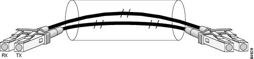
For single-mode and multimode optical fiber connections, you can use either a duplex LC-type cable (see Figure 2-33) or two simplex LC-type cables, one for transmit (TX) and one for receive (RX).
Use single-mode (for intermediate-reach or long-reach configurations) or multimode optical fiber cable to connect your router to a network or to connect two 2-Port and 4-Port OC-3/STM-1 POS SPA-equipped routers back-to-back.
Long-range SFP optical transceiver modules (for long-reach configurations) cannot be connected back-to-back without using an attenuator between them.
OC-3 Module Connections
Table 2-34 shows the OC-3 specifications of the optics on the 2-Port and 4-Port OC-3/STM-1 POS SPA.
8-Port OC-3 STM-1/OC-12 STM-4 POS SPA Overview
The 8-Port OC-3 STM-1/OC-12 STM-4 POS SPA is a single-height SPA that installs into one SIP subslot. The SPA with small form-factor pluggable (SFP) optical transceiver modules provides Optical Carrier Level (OC- n) for SONET and Synchronous Transport Module (STM- n) for SDH network connectivity. On this SPA, any given port can use either an OC-3 or OC-12 SFP module, so the per-port bandwidth can be either 155.52 Mbps or 622.08 Mbps, respectively, depending on the customer configuration.
Note![]() When SFP modules are replaced, the SPA interface retains any previously defined configurations. These configurations include settings for IP address, clock source, loopback, CRC, and POS flags.
When SFP modules are replaced, the SPA interface retains any previously defined configurations. These configurations include settings for IP address, clock source, loopback, CRC, and POS flags.
For more information about SPA bandwidth, see the “Bandwidth Oversubscription” topic in this chapter. For more information about SPAs and their compatibility with SIPs and modular optics, see the “SIP and SPA Product Overview” chapter in this guide.
The following sections describe the 8-Port OC-3 STM-1/OC-12 STM-4 POS SPA:
- 8-Port OC-3 STM-1/OC-12 STM-4 POS SPA LEDs
- 8-Port OC-3 STM-1/OC-12 STM-4 POS SPA Interface Specifications
- 8-Port OC-3 STM-1/OC-12 STM-4 POS SPA Optical Transceiver Modules and Cables
8-Port OC-3 STM-1/OC-12 STM-4 POS SPA LEDs
The 8-Port OC-3 STM-1/OC-12 STM-4 POS SPA has three types of LEDs: two LEDs for each port on the SPA and one STATUS LED. Figure 2-34 shows the 8-Port OC-3 STM-1/OC-12 STM-4 POS SPA faceplate.
Figure 2-34 8-Port OC-3 STM-1/OC-12 STM-4 POS SPA Faceplate
|
|
|
||
|
|
|
Table 2-35 describes the 8-Port OC-3 STM-1/OC-12 STM-4 POS SPA LEDs.
|
|
|
|
|
|---|---|---|---|
Port is enabled by software, and there is a valid SONET signal without any alarms. |
|||
Port is enabled by software, and there is at least one alarm. |
|||
8-Port OC-3 STM-1/OC-12 STM-4 POS SPA Interface Specifications
The framer processes incoming and outgoing SONET or SDH frames. The framer operates at OC-3 line rates (155.52 Mbps) and OC-12 line rates (622.08 Mbps). Packet data is transported with a user-configured encapsulation (such as Point-to-Point Protocol [PPP]) and is mapped into the Layer 2 frame.
The 8-Port OC-3 STM-1/OC-12 STM-4 POS SPA interface complies with the following RFCs:
8-Port OC-3 STM-1/OC-12 STM-4 POS SPA Optical Transceiver Modules and Cables
The 8-Port OC-3 STM-1/OC-12 STM-4 POS SPA uses a small form-factor pluggable (SFP) optical transceiver module installed in each port for SONET and SDH single-mode and multimode optical fiber connections (see Figure 2-35).
Cisco Systems qualifies the optics that are approved for use with its SPAs. The following OC-3 optical transceiver modules are supported on the 8-Port OC-3 STM-1/OC-12 STM-4 POS SPA:
- Multimode (MM) SFP module—SFP-OC3-MM
- Short-reach (SR) SFP module—SFP-OC3-SR
- Intermediate-reach (IR) SFP module (15 km)—SFP-OC3-IR1
- Long-reach (LR) SFP module (40 km)—SFP-OC3-LR1
- Long-reach (LR) SFP module (80 km)—SFP-OC3-LR2
The following OC-12 optical transceiver modules are supported on the 8-Port OC-3 STM-1/OC-12 STM-4 POS SPA:
- Multimode (MM) SFP module—SFP-OC12-MM
- Short-reach (SR) SFP module—SFP-OC12-SR
- Intermediate-reach (IR) SFP module (15 km)—SFP-OC12-IR1
- Long-reach (LR) SFP module (40 km)—SFP-OC12-LR1
- Long-reach (LR) SFP module (80 km)—SFP-OC12-LR2
The following OC-3 optical fiber options are available for the 8-Port OC-3 STM-1/OC-12 STM-4 POS SPA:
Use a multimode optical fiber that has a core/cladding diameter of 62.5/125 microns.
Use a single-mode optical fiber that has a modal-field diameter of 8.7 ± 0.5 microns. (Nominal diameter is approximately 10/125 microns.)
The following OC-12 optical fiber options are available for the 8-Port OC-3 STM-1/OC-12 STM-4 POS SPA:
Use a multimode optical fiber that has a core/cladding diameter of 62.5/125 microns.
Use a single-mode optical fiber that has a modal-field diameter of 8.7 ± 0.5 microns. (Nominal diameter is approximately 10/125 microns.)
For single-mode and multimode optical fiber connections, you can use either a duplex LC-type cable (see Figure 2-36) or two simplex LC-type cables, one for transmit (TX) and one for receive (RX).
Use single-mode (for short-, intermediate- or long-reach configurations) or multimode optical fiber cable to connect your router to a network or two OC-3-equipped or OC-12-equipped routers back-to-back.
Long-range SFP optical transceiver modules (for long-reach configurations) cannot be connected back-to-back without using an attenuator between them.
OC-3 Module Connections
Table 2-36 shows the OC-3 specifications of the optics on the 8-Port OC-3 STM-1/OC-12 STM-4 POS SPA.
OC-12 Module Connections
Table 2-37 shows the OC-12 specifications of the optics on the 8-Port OC-3 STM-1/OC-12 STM-4 POS SPA.
1-Port OC-12/STM-4 POS SPA Overview
The 1-Port OC-12/STM-4 POS SPA is single-height SPA that installs into one SIP subslot. The 1-Port OC-12/STM-4 POS SPA with a small form-factor pluggable (SFP) optical transceiver module provides SONET and SDH network connectivity with a bandwidth of 622.08 Mbps.
For more information about SPA bandwidth, see the “Bandwidth Oversubscription” topic in this chapter. For more information about SPAs and their compatibility with SIPs and modular optics, see the “SIP and SPA Product Overview” chapter in this guide.
The following sections describe the 1-Port OC-12/STM-4 POS SPA:
- 1-Port OC-12/STM-4 POS SPA LEDs
- 1-Port OC-12/STM-4 POS SPA Interface Specifications
- 1-Port OC-12/STM-4 POS SPA SFP Optical Transceiver Modules and Cables
1-Port OC-12/STM-4 POS SPA LEDs
The 1-Port OC-12/STM-4 POS SPA has three types of LEDs. There are two LEDs for each port on the SPA, and one STATUS LED. Figure 2-37 shows an example of these LEDs on a 1-Port OC-12/STM-4 POS SPA.
Figure 2-37 1-Port OC-12/STM-4 POS SPA Faceplate

|
|
|
||
|
|
|
The 1-Port OC-12/STM-4 POS SPA LEDs are described in Table 2-38 .
|
|
|
|
|
|---|---|---|---|
Port is enabled by software, and there is a valid SONET signal without any alarms. |
|||
Port is enabled by software, and there is at least one alarm. |
|||
1-Port OC-12/STM-4 POS SPA Interface Specifications
The framer processes incoming and outgoing SONET or SDH frames. The framer operates at OC-12/STM-4 line rates (622.08 Mbps).
Packet data is transported with a user-configured encapsulation (such as Point-to-Point Protocol [PPP]) and is mapped into the STS-12/STM-4 frame.
The 1-Port OC-12/STM-4 POS SPA interface is compliant with the following RFCs:
The 1-Port OC-12/STM-4 POS SPA also provides support for SNMP v1 agent (RFC 1155–1157) and RFC 1213:
- RFC 1155, Structure and Identification of Management Information for TCP/IP-based Internets
- RFC 1156, Management Information Base for Network Management of TCP/IP-Based Internets
- RFC 1157, Simple Network Management Protocol (SNMP)
- RFC 1213, Management Information Base (MIB) for Network Management of TCP/IP-Based Internets:MIB II.
1-Port OC-12/STM-4 POS SPA SFP Optical Transceiver Modules and Cables
The POS SPA uses a small form-factor pluggable (SFP) optical transceiver module installed in each port for SONET and SDH single-mode and multimode optical fiber connection (see Figure 2-38).
Cisco Systems qualifies the optics that are approved for use with its SPAs. The 1-Port OC-12/STM-4 POS SPA supports the following types of optical transceiver modules:
- Multimode (MM) SFP module—SFP-OC12-MM
- Short reach (SR) SFP module—SFP-OC12-SR
- Intermediate reach (IR) SFP module (15 km)—SFP-OC12-IR1
- Long reach (LR) SFP module (40 km)—SFP-OC12-LR1
- LR SFP module (80 km)—SFP-OC12-LR2
The SFP optical transceiver modules used with the POS SPAs provide the following optical fiber options:
Use a multimode optical fiber that has a core/cladding diameter of 62.5/125 microns.
Use a single-mode optical fiber that has a modal-field diameter of 8.7 ±0.5 microns. (Nominal diameter is approximately 10/125 microns.)
For single-mode and multimode optical fiber connections, you can use either a duplex LC-type cable (see Figure 2-39) or two simplex LC-type cables, one for transmit (TX) and one for receive (RX).
Use single-mode (for intermediate- or long-reach configurations) or multimode optical fiber cable to connect your router to a network or to connect two 1-Port OC-12/STM-4 POS SPA-equipped routers back to back.
Long-range SFP optical transceiver modules (for long-reach configurations) cannot be connected back-to-back without using an attenuator between the two of them.
1-Port OC-48/STM-16 POS SPA Overview
The 1-Port OC-48/STM-16 POS SPA is a single-height SPA that is installed in a SIP subslot. The 1-Port OC-48/STM-16 POS SPA provides RPR over SONET (IEEE 802.17), SRP over SONET (Cisco Proprietary), and Packet over SONET (POS) network connectivity with a bandwidth of 9.95 Gbps.
For more information about SPA bandwidth, see the “Bandwidth Oversubscription” topic in this chapter. For more information about SPAs and their compatibility with SIPs and modular optics, see the “SIP and SPA Product Overview” chapter in this guide.
The following sections describe the 1-Port OC-48/STM-16 POS SPA:
- 1-Port OC-48/STM-16 POS SPA LEDs
- 1-Port OC-48/STM-16 POS SPA Interface Specifications
- 1-Port OC-48/STM-16 POS SPA Optical Transceiver Modules, Connectors, and Cables
1-Port OC-48/STM-16 POS SPA LEDs
The 1-Port OC-48/STM-16 POS SPA has six LEDs, as shown in Figure 2-40.
Figure 2-40 1-Port OC-48/STM-16 POS SPA Faceplate

|
|
|
||
|
|
|
||
|
|
|
||
|
|
|
Note![]() The WRAP, PASSTHRU, and MATESYNC LEDs apply to the SPA in RPR/SRP mode only.
The WRAP, PASSTHRU, and MATESYNC LEDs apply to the SPA in RPR/SRP mode only.
The 1-Port OC-48/STM-16 POS SPA LEDs are described in Table 2-39 .
1-Port OC-48/STM-16 POS SPA Interface Specifications
The framer processes incoming and outgoing SONET or SDH frames. The framer operates at OC-48/STM-64 line rates (9.95 Gbps).
Packet data is transported with a user-configured encapsulation (such as Point-to-Point Protocol [PPP]) and is mapped into the STS-48/STM-64 frame.
The 1-Port OC-48/STM-16 POS SPA interface is compliant with the following RFCs:
1-Port OC-48/STM-16 POS SPA Optical Transceiver Modules, Connectors, and Cables
The 1-Port OC-48/STM-16 POS SPA uses a single-mode, 9.95 Gbps, OC-48 optical fiber (SONET STS-48) optical transceiver module for SONET connection to the network.
The 1-Port OC-48/STM-16 POS SPA supports the following type of optical transceiver module:
- Single-mode short reach (SR) SFP module—SFP-OC48-SROC-48/STM-16c
- Single-mode intermediate reach (IR) SFP module—SFP-OC48-IR1OC-48/STM-16c
- Single-mode long reach (LR) SFP module—SFP-OC48-LR2OC-48/STM-16c
Use a single-mode optical fiber that has a modal-field diameter of 8.7 ±0.5 microns (nominal diameter is approximately 10/125 microns) to connect your router to a network.
Figure 2-41 shows the cable type for use with the XFP optical transceiver module on the 1-Port OC-48/STM-16 POS SPA.
Figure 2-41 LC-Type Cable for the SFP Optical Transceiver Modules

Note![]() The 40-pin connector on the 1-Port OC-48/STM-16 POS SPA is used for resilient packet ring (RPR) connections.
The 40-pin connector on the 1-Port OC-48/STM-16 POS SPA is used for resilient packet ring (RPR) connections.
Mate Interface Cables
The 1-Port OC-48/STM-16 POS SPA supports two mate interface configurations:
Two 1-Port OC-48/STM-16 POS SPAs are connected using a 40–pin connector copper mate cable. The length of the cables allow only two possible connection scenarios, next slot horizontal and same slot vertical. This assumes that the chassis is mounted vertically. Figure 2-42 shows the mate cables used to connect the SPAs.
|
|
Long length RPR mate cable for single port RPR SPAs (CBL-RPR-OC48-L) |
|
Short length RPR mate cable for single port RPR SPAs (CAB-RPR-OC48-S) |
Note![]() The RPR mate cable is necessary only when the SPA is to be used in RPR mode. It is not needed in POS mode. Support for the RPR feature is dependent on the platform software release feature content. Verify support for the RPR feature support by reviewing the relevant SPA datasheets or by contacting your Cisco representative.
The RPR mate cable is necessary only when the SPA is to be used in RPR mode. It is not needed in POS mode. Support for the RPR feature is dependent on the platform software release feature content. Verify support for the RPR feature support by reviewing the relevant SPA datasheets or by contacting your Cisco representative.
2-Port and 4-Port OC-48/STM-16 POS SPA Overview
The following sections describe the 2-Port and 4-Port OC-48/STM-16 POS SPA:
- 2-Port and 4-Port OC-48/STM-16 POS SPA LEDs
- 2-Port and 4-Port OC-48/STM-16 POS SPA Interface Specifications
- 2-Port and 4-Port OC-48/STM-16 POS SPA Cables, Optical Transceiver Modules, and Connectors
2-Port and 4-Port OC-48/STM-16 POS SPA LEDs
The 2-Port and 4-Port OC-48/STM-16 POS SPA has five types of LEDs: four LEDs for each port on the SPA and one STATUS LED, as shown in Figure 2-43.
Figure 2-43 2-Port OC-48 POS/RPR SPA Faceplate

|
|
|
||
|
|
|
||
|
|
|
Table 2-40 describes the 2-Port and 4-Port OC-48/STM-16 POS SPA LEDs.
|
|
|
|
|
|---|---|---|---|
Port is enabled by software, and there is a valid SONET signal without any alarms. |
|||
Port is enabled by software, and there is at least one alarm. |
|||
2-Port and 4-Port OC-48/STM-16 POS SPA Interface Specifications
The physical layer interface for the 2-Port and 4-Port OC-48/STM-16 POS SPA is Optical Carrier-48 (OC-48), and provides SONET and SDH network connectivity with a per-port bandwidth of 2.488 Gbps.
Each port on the 2-Port and 4-Port OC-48/STM-16 POS SPA has one duplex LC-type receptacle that allows connection to single-mode optical fiber.
2-Port and 4-Port OC-48/STM-16 POS SPA Cables, Optical Transceiver Modules, and Connectors
Use single-mode (for intermediate-reach configurations) optical fiber cable to connect your router to a network or to connect two OC-48-equipped routers back-to-back.
The 2-Port and 4-Port OC-48/STM-16 POS SPA supports the following types of optical transceiver modules:
- Single-mode short-reach (SR) SFP module—SFP-OC48-SR OC48/STM16c
- Single-mode intermediate-reach (IR) SFP module—SFP-OC48-IR1 OC48/STM16c
- Single-mode long-reach (LR) SFP module—SFP-OC48-LR2 OC48/STM16c
Each port on the 2-Port and 4-Port OC-48/STM-16 POS SPA has one duplex LC-type receptacle. For single-mode optical fiber connections, you can use either a duplex LC-type cable (see Figure 2-44) or two simplex LC-type cables, one for transmit (TX) and one for receive (RX).
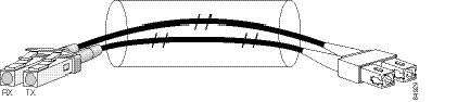
OC-48 Module Connections
Table 2-41 shows the OC-48 specifications for use with the 2-Port and 4-Port OC-48/STM-16 POS SPA.
Mate Interface Cables
The 2-Port and 4-Port OC-48/STM-16 POS SPA supports two mate interface configurations:
Two SPAs are connected using a 40–pin connector copper mate cable. The length of the cables allow only two possible connection scenarios, next slot horizontal and same slot vertical. This assumes that the chassis is mounted vertically. Figure 2-45 shows the mate cables used to connect the SPAs.
|
|
Long length RPR mate cable for single port RPR SPAs (CBL-RPR-OC192-L) |
|
Short length RPR mate cable for single port RPR SPAs (CAB-RPR-OC192-S) |
2-Port OC-48 POS RPR SPA Overview
The following sections describe the 2-Port OC48-POS/RPR SPA:
- 2-Port OC48-POS/RPR SPA LEDs
- 2-Port OC48-POS/RPR SPA Interface Specifications
- 2-Port OC48-POS/RPR SPA Cables, Optical Transceiver Modules, and Connectors
2-Port OC48-POS/RPR SPA LEDs
The 2-Port OC48-POS/RPR SPA has five LEDs, as shown in Figure 2-46.
Figure 2-46 2-Port OC48-POS/RPR SPA Faceplate
|
|
|
||
|
|
|
||
|
|
|
The 2-Port OC48-POS/RPR SPA LEDs are described in Table 2-42 .
|
|
|
|
|
|---|---|---|---|
Port is enabled by software, and there is a valid SONET signal without any alarms. |
|||
Port is enabled by software, and there is at least one alarm. |
|||
2-Port OC48-POS/RPR SPA Interface Specifications
The physical layer interface for the 2-Port OC48-POS/RPR SPA is Optical Carrier-48 (OC-48), and the 2-Port OC48-POS/RPR SPA is designed to comply with POS specifications. The 2-Port OC48-POS/RPR SPA provides two 2.488-Gbps network interfaces for all supported platforms.
2-Port OC48-POS/RPR SPA Cables, Optical Transceiver Modules, and Connectors
Use single-mode (for intermediate-configurations) optical fiber cable to connect your router to a network or to connect two OC-48-equipped routers back-to-back.
The 2-Port OC48-POS/RPR SPA supports the following types of optical transceiver modules:
- Single-mode short-reach (SR) SFP module—SFP-OC48-SR
- Single-mode intermediate-reach (IR) SFP module —SFP-OC48-IR1
- Single-mode long-reach (LR) SFP module — SFP-OC48-LR2
Each port on the 2-Port OC48-POS/RPR SPA has one duplex LC-type receptacle. For single-mode optical fiber connections, you can use either a duplex LC-type cable (see Figure 2-47) or two simplex LC-type cables, one for transmit (TX) and one for receive (RX).
Figure 2-47 Duplex Patch Cable with LC-Type Connectors
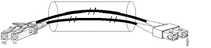
Cisco XR12000 IPSec VPN SPA Overview
The Cisco XR12000 IPSec VPN SPA (SPA) provides remote access and remote site VPN connectivity for the Cisco XR 12000 Series Router.
The following features are supported:
- Site-to-Site communication over point-to-point IPSec/GRE tunnels
- Remote User Access over IPSec tunnels.
Any slot of the Cisco XR 12000 Series Router that contains a Cisco XR 12000 SIP-401, Cisco XR 12000 SIP-501, or a Cisco XR 12000 SIP-601 can support up to two Cisco XR12000 IPSec VPN SPAs, or any mixture of the Cisco XR12000 IPSec VPN SPA with other interface SPA types on the same SIP card.
Note that the Cisco XR12000 IPSec VPN SPA (SPA-IPSEC-2G-2) supported on the Cisco XR 12000 Series Router is a different form factor from the IPSec VPN SPA supported on the Cisco 7600 router (SPA-IPSEC-2G-1).
Warning![]() Attempting to install a SPA-IPSEC-2G-1 into a Cisco XR 12000 SIP-401, Cisco XR 12000 SIP-501, or a Cisco XR 12000 SIP-601 will result in mounting rail damage. Only the Cisco XR12000 IPSec VPN SPA (SPA-IPSEC-2G-2) is supported on the Cisco XR 12000 Series Router.
Attempting to install a SPA-IPSEC-2G-1 into a Cisco XR 12000 SIP-401, Cisco XR 12000 SIP-501, or a Cisco XR 12000 SIP-601 will result in mounting rail damage. Only the Cisco XR12000 IPSec VPN SPA (SPA-IPSEC-2G-2) is supported on the Cisco XR 12000 Series Router.
The following sections describe the IPSec VPN SPA:
IPSec VPN SPA LEDs
The IPSec VPN SPA has one LED, as shown in Figure 2-48.
Figure 2-48 IPSec VPN SPA Faceplate

|
|
|
The IPSec VPN SPA LED is described in Table 2-43 .
|
|
|
|
|
|---|---|---|---|

1-Port and 3-Port Clear Channel OC-3 ATM SPA Overview
The 1-Port and 3-Port Clear Channel OC-3 ATM SPA is a single-height SPA that installs into one SIP subslot. The Clear Channel OC-3 ATM SPA with small form-factor pluggable (SFP) optical transceiver modules provides SONET and SDH network connectivity with a per-port bandwidth of 155.52 Mbps. For more information about SPA bandwidth, see the “Bandwidth Oversubscription” section in this chapter.
The following sections describe the 1-Port and 3-Port Clear Channel OC-3 ATM SPA:
- 1-Port and 3-Port Clear Channel OC-3 ATM SPA LEDs
- 1-Port and 3-Port Clear Channel OC-3 ATM SPA Interface Specifications
- 1-Port and 3-Port Clear Channel OC-3 ATM SPA Cables and Connectors
1-Port and 3-Port Clear Channel OC-3 ATM SPA LEDs
The 1-Port and 3-Port Clear Channel OC-3 ATM SPA has three types of LEDs. There are two LEDs for each port on the SPA, and one STATUS LED. Figure 2-49 shows an example of these LEDs on a 3-Port Clear Channel OC-3 ATM SPA.
Figure 2-49 3-Port Clear Channel OC-3 ATM SPA Faceplate

|
|
|
||
|
|
|
The 1-Port and 3-Port Clear Channel OC-3 ATM SPA LEDs are described in Table 2-44 .
1-Port and 3-Port Clear Channel OC-3 ATM SPA Interface Specifications
The physical layer interface for the 1-Port and 3-Port Clear Channel OC-3 ATM SPA is Optical Carrier-3 (OC-3), and the data link layer is designed to comply with ATM specifications. The 1-Port and 3-Port Clear Channel OC-3 ATM SPA provides up to one and three 155-Mbps OC-3 network interfaces, respectively, for all supported platforms.
Each SPA port accepts an SFP module with a duplex LC-type receptacle that allows connection to single-mode or multimode optical fiber.
1-Port and 3-Port Clear Channel OC-3 ATM SPA Cables and Connectors
The 1-Port and 3-Port Clear Channel OC-3 ATM SPA uses a small form-factor pluggable (SFP) optical transceiver module installed in each port for SONET and SDH single-mode and multimode optical fiber connection (see Figure 2-50).
The SFP optical transceiver modules used with the 1-Port and 3-Port Clear Channel OC-3 ATM SPA provide the following optical fiber options:
Use a multimode optical fiber that has a core/cladding diameter of 62.5/125 microns.
Use a single-mode optical fiber that has a modal-field diameter of 8.7 ± 0.5 microns. (Nominal diameter is approximately 10/125 microns.)
For single-mode and multimode optical fiber connections, you can use either a duplex LC-type cable (see Figure 2-51) or two simplex LC-type cables, one for transmit (TX) and one for receive (RX).
Use a single-mode (for intermediate-reach or long-reach configurations) or multimode optical fiber cable to connect your router to a network or to connect two OC-3-equipped routers back-to-back.
Long-range SFP optical transceiver modules (for long-reach configurations) cannot be connected back-to-back without using an attenuator between them.
Figure 2-51 Duplex Patch Cable with LC-Type Connectors
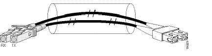
1-Port Clear Channel OC-12 ATM SPA Overview
The 1-Port Clear Channel OC-12 ATM SPA is a single-height ATM SPA that can be installed into one SIP subslot. The OC-12 ATM SPA with small form-factor pluggable (SFP) optical transceiver modules provides SONET and SDH network connectivity with a per-port bandwidth of 622.08 Mbps. For more information about SPA bandwidth, see the “Bandwidth Oversubscription” section in this chapter.
The following sections describe the 1-Port Clear Channel OC-12 ATM SPA:
- 1-Port Clear Channel OC-12 ATM SPA LEDs
- 1-Port Clear Channel OC-12 ATM SPA Interface Specifications
- 1-Port Clear Channel OC-12 ATM SPA Cables and Connectors
1-Port Clear Channel OC-12 ATM SPA LEDs
The 1-Port Clear Channel OC-12 ATM SPA has three types of LEDs. There are two LEDs for the port on the SPA, and one STATUS LED, as shown in Figure 2-52.
Figure 2-52 1-Port Clear Channel OC-12 ATM SPA Faceplate

|
|
|
||
|
|
|
The 1-Port Clear Channel OC-12 ATM SPA LEDs are described in Table 2-45 .
|
|
|
|
|
|---|---|---|---|
Port is enabled by software, and there is a valid SONET signal without any alarms. |
|||
Port is enabled by software, and there is at least one alarm. |
|||
1-Port Clear Channel OC-12 ATM SPA Interface Specifications
The physical layer interface for the 1-Port Clear Channel OC-12 ATM SPA is Optical Carrier-12 (OC-12), and the 1-Port Clear Channel OC-12 ATM SPA is designed to comply with ATM specifications. The 1-Port Clear Channel OC-12 ATM SPA provides one 622.08 Mbps OC-12 network interface for all supported platforms.
The single SPA port accepts an SFP module with a duplex LC-type receptacle that allows connection to single-mode or multimode optical fiber.
1-Port Clear Channel OC-12 ATM SPA Cables and Connectors
The 1-Port Clear Channel OC-12 ATM SPA uses a small form-factor pluggable (SFP) optical transceiver module installed in each port for SONET and SDH single-mode and multimode optical fiber connection (see Figure 2-53).
The 1-Port Clear Channel OC-12 ATM SPA supports the following types of optical transceiver modules:
Multimode (MM) SFP module—SFP-OC12-MM
Short-reach (SR) SFP module—SFP-OC12-SR
Intermediate-reach (IR) SFP module (15 km)—SFP-OC12-IR1
Long-reach (LR) SFP module (40 km)—SFP-OC12-LR1
Long-reach (LR) SFP module (80 km)—SFP-OC12-LR2
The SR, IR, and LR1 transceivers provide a full-duplex 622.08-Mbps, laser-based SONET/SDH- compliant interface with an average wavelength of 1310 nm. The LR2 transceivers provide a full-duplex, 622.08-Mbps, laser-based SONET/SDH-compliant interface with an average wavelength of 1530 nm. The multimode transceiver provides a full-duplex, 622.08-Mbps, LED-based SONET/SDH-compliant interface with an average wavelength of 1325 nm.
The 1-Port Clear Channel OC-12 ATM SPA provides the following optical fiber options:
Use a multimode optical fiber that has a core/cladding diameter of 62.5/125 microns.
Use a single-mode optical fiber that has a modal-field diameter of 8.7 ±0.5 microns. (Nominal diameter is approximately 10/125 microns.)
For single-mode and multimode optical fiber connections, you can use either a duplex LC-type cable (see Figure 2-54) or two simplex LC-type cables, one for transmit (TX) and one for receive (RX).
Figure 2-54 Duplex Patch Cable with LC-Type Connectors
2-Port Channelized T3/E3 ATM CEoP SPA Overview
The following sections describe the 2-Port Channelized T3/E3 ATM CEoP SPA:
- 2-Port Channelized T3/E3 ATM CEoP SPA LEDs
- 2-Port Channelized T3/E3 ATM CEoP SPA Interface Specifications
- 2-Port Channelized T3/E3 ATM CEoP SPA Cables and Connectors
2-Port Channelized T3/E3 ATM CEoP SPA LEDs
The 2-Port Channelized T3/E3 ATM CEoP SPA has three types of LEDs (see Figure 2-55). There are two LEDs for each port on the SPA, and a single STATUS LED for the SPA.
Figure 2-55 2-Port Channelized T3/E3 ATM CEoP SPA Faceplate

|
|
|
||
|
|
|
||
|
|
|
The 2-Port Channelized T3/E3 ATM CEoP SPA LEDs are described in Table 2-46 .
|
|
|
|
|
|---|---|---|---|
Port is enabled by software, and there is at least one alarm. |
|||
2-Port Channelized T3/E3 ATM CEoP SPA Interface Specifications
The framer processes incoming and outgoing T3 (cbit, m13/m23, and unframe) and E3 (g751 and unframe) frames. The framer operates at T3 or E3 line rates (44.736 or 34.368 Mbps), depending on the mode in which it is configured.
Note![]() For Cisco IOS XR Software Release 3.7.0, the 2-Port Channelized T3/E3 ATM CEoP SPA supports T3 ATM only. E3 ATM is not supported.
For Cisco IOS XR Software Release 3.7.0, the 2-Port Channelized T3/E3 ATM CEoP SPA supports T3 ATM only. E3 ATM is not supported.
T3/E3 data is encapsulated and sent across the MPLS network over user-configurable pseudowires. In ATM mode, data is encapsulated into ATM cells and transported across the network.
In circuit emulation (CE) mode, channelized data is encapsulated in structured mode using the Circuit Emulation Services over Packet Switched Network (CESoPSN) format, and unchannelized data is encapsulated in unstructured mode using Structure-Agnostic TDM over Packet (SAToP) format. The encapsulation adds transport overhead to the CEM frames or ATM cells before transport and removes the overhead at the far end.
Note![]() For Cisco IOS XR Software Release 3.7.0, the 2-Port Channelized T3/E3 ATM CEoP SPA does not support circuit emulation (CE) mode.
For Cisco IOS XR Software Release 3.7.0, the 2-Port Channelized T3/E3 ATM CEoP SPA does not support circuit emulation (CE) mode.
The T3/E3 SPA interface is compliant with ANSI and Telco standards. The interface also provides support for Management Information Base (MIB) RFC 2495, RFC 2496, and T1.231.
2-Port Channelized T3/E3 ATM CEoP SPA Cables and Connectors
The interface connectors on the 2-Port Channelized T3/E3 ATM CEoP SPA are 75-ohm coaxial Siemax types, with one connector and cable for transmit (TX) and one for receive (RX).
The following cables can be used with the 2-Port Channelized T3/E3 ATM CEoP SPA. The cables have BNC connectors on one end and the Siemax connectors on the other. If similar SPAs are connected back-to-back, both ends of the cable are Siemax.
- CAB-T3E3-RF-BNC-M (T3 or E3 Cable, 1.0/2.3 RF to BNC-Male, 10 feet)
- CAB-T3E3-RF-BNC-F (T3 or E3 Cable, 1.0/2.3 RF to BNC-Female, 10 feet)
- CAB-T3E3-RF-OPEN (T3 or E3 Cable, 1.0/2.3 RF to BNC-Open end, 10 feet)
Note ●![]() The Cisco cable part numbers are 72-4124-01 (with male BNC end) and 72-4131-01 (with female BNC end).
The Cisco cable part numbers are 72-4124-01 (with male BNC end) and 72-4131-01 (with female BNC end).
Figure 2-55 shows the connectors on the 2-Port Channelized T3/E3 ATM CEoP SPA, and Table 2-47 describes the signal descriptions for these connectors.
24-Port Channelized T1/E1/J1 ATM CEoP SPA Overview
The following sections describe the 24-Port Channelized T1/E1/J1 ATM CEoP SPA:
- 24-Port Channelized T1/E1/J1 ATM CEoP SPA LEDs
- 24-Port Channelized T1/E1/J1 ATM CEoP SPA Interface Specifications
- 24-Port Channelized T1/E1/J1 ATM CEoP SPA Cables and Connectors
- 24-Port Channelized T1/E1/J1 ATM CEoP SPA Patch Panel
24-Port Channelized T1/E1/J1 ATM CEoP SPA LEDs
The 24-Port Channelized T1/E1/J1 ATM CEoP SPA has two types of LEDs, as shown in this figure:
Figure 2-56 24-Port Channelized T1/E1/J1 ATM CEoP SPA Faceplate

|
|
|
The 24-Port Channelized T1/E1/J1 ATM CEoP SPA LEDs are described in the following table.
|
|
|
|
|
|---|---|---|---|
Port is enabled by software, and there is at least one alarm. |
24-Port Channelized T1/E1/J1 ATM CEoP SPA Interface Specifications
The physical layer interface for the 24-Port Channelized T1/E1/J1 ATM CEoP SPA is a customer-installed high-density connector. The high-density connector has thumbscrews which should be screwed into the SPA when the cable is installed.
24-Port Channelized T1/E1/J1 ATM CEoP SPA Cables and Connectors
The 24-Port Channelized T1/E1/J1 ATM CEoP SPA requires a Cisco cable (part number CABLE-24T1E1J1), which is shown in the following figure.
Figure 2-57 24-Port Channelized T1/E1/J1 ATM CEoP SPA High-Density Cable

Cable Installation
One end of the cable has a 100-pin connector that plugs into the front of the 24-Port Channelized T1/E1/J1 ATM CEoP SPA. Use the thumbscrews on either side of the connector to secure the cable to the SPA.
The other end of the cable has two 50-pin Telco connectors that attach to the rear of a 24-port RJ-45 patch panel. Both connectors are identical: one is for Transmit (TX) and the other is for Receive (RX). The following figure shows how the cable is connected between the 24-Port Channelized T1/E1/J1 ATM CEoP SPA and the patch panel.
Figure 2-58 Cable Installation between SPA and Patch Panel

SPA Cable Pinouts
The following table shows the cable pinouts for the cable (part number CABLE-24T1E1J1) that is installed between the 24-Port Channelized T1/E1/J1 ATM CEoP SPA and the rear of the patch panel.
|
|
|
|||
|---|---|---|---|---|
|
|
|
|
|
|
RJ-45 Cable Pinouts
T1 lines from individual subscribers are attached to RJ-45 connectors on the front of the 24-port patch panel. Each RJ-45 port accommodates an individual T1 subscriber line.
Pins 1 and 2 and 4 and 5 of the RJ-45 connectors are used for the 24-port CEoP SPA’s Transmit (TX) and Receive (RX) signals. Depending on how the cable is installed between the SPA and its patch panel (rear), the RJ-45 connectors operate as follows:
–![]() The SPA’s TX signals are transmitted on RJ-45 pins 1 (ring) and 2 (tip).
The SPA’s TX signals are transmitted on RJ-45 pins 1 (ring) and 2 (tip).
–![]() The SPA’s RX signals are received on RJ-45 pins 4 (ring) and 5 (tip).
The SPA’s RX signals are received on RJ-45 pins 4 (ring) and 5 (tip).
Patch Panel Cabling
If you are connecting two 24-Port Channelized T1/E1/J1 ATM CEoP SPAs to each other, you must cable both SPA’s patch panels together using a T1 cross-over cable or a T1 straight-through cable. The type of cable you use (cross-over or straight-through) depends on how the CEoP SPAs are cabled to their patch panels:
- If both CEoP SPAs are connected to their patch panels in the same manner (TX to Transmit and RX to Receive, or TX to Receive and RX to Transmit), use a T1 cross-over cable to connect the patch panels to each other.
- If both CEoP SPAs are connected to their patch panels in a different configuration (TX to Transmit and RX to Receive on one SPA, and TX to Receive and RX to Transmit on the other SPA), use a T1 straight-through cable (standard RJ-45 patch cable) between the patch panels.
24-Port Channelized T1/E1/J1 ATM CEoP SPA Patch Panel
The recommended patch panel is part number DCC2484/25T1S from SMP Data Communications ( http://www.smpdata.com).
To order the patch panel, contact the Sales and Marketing Support staff at SMP Data Communications:
- 800-880-7674 (toll free in the U.S.A.)
- 828-298-2260 (outside the U.S.A.)
- ciscoinfo@smpdata.com (email)
For product support for the patch panel, contact Cisco Engineering Support at SMP Data Communications:
1-Port Channelized OC-3 ATM CEoP SPA Overview
The following sections describe the 1-Port Channelized OC-3 ATM CEoP SPA:
- 1-Port Channelized OC-3 ATM CEoP SPA LEDs
- 1-Port Channelized OC-3 ATM CEoP SPA Interface Specifications
- 1-Port Channelized OC-3 ATM CEoP SPA Optical Transceiver Modules and Cables
1-Port Channelized OC-3 ATM CEoP SPA LEDs
The 1-Port Channelized OC-3 ATM CEoP SPA has three types of LEDs. There are two LEDs for the port on the SPA, and one STATUS LED as shown in the following figure.
Figure 2-59 1-Port Channelized OC-3 ATM CEoP SPA Faceplate

|
|
|
||
|
|
|
The 1-Port Channelized OC-3 ATM CEoP SPA LEDs are described in the following table.
|
|
|
|
|
|---|---|---|---|
Port is enabled by software, and there is at least one alarm. |
|||
1-Port Channelized OC-3 ATM CEoP SPA Interface Specifications
The physical layer interface for the 1-Port Channelized OC-3 ATM CEoP SPA is Optical Carrier-3 (OC-3). The 1-Port Channelized OC-3 ATM CEoP SPA provides one 155.52-Mbps OC-3 network interface for all supported platforms.
The single SPA port accepts an SFP module with a duplex LC-type receptacle that allows connection to optical fiber.
1-Port Channelized OC-3 ATM CEoP SPA Optical Transeiver Modules and Cables
Cisco Systems qualifies the optics that are approved for use with its SPAs. The 1-Port Channelized OC-3 ATM CEoP SPA supports the following types of optical transceiver modules:
1-Port 10-Gigabit Ethernet DWDM SPA Overview
The following sections describe the 1-Port 10-Gigabit Ethernet DWDM SPA:
- 1-Port 10-Gigabit Ethernet SPA LEDs
- 1-Port 10-Gigabit Ethernet SPA XFP Optical Transceiver Modules, Connectors, and Cables
1-Port 10-Gigabit Ethernet DWDM SPA LEDs
The 1-Port 10-Gigabit Ethernet DWDM SPA has three LEDs: an ACTIVE/LINK LED for the port, a CARRIER LED, and a STATUS LED, as shown in this figure.
Figure 2-60 1-Port 10-Gigabit Ethernet DWDM SPA Faceplate
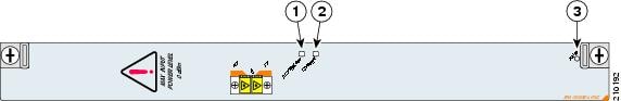
|
|
|
||
|
|
|
The 1-Port 10-Gigabit Ethernet DWDM SPA LEDs are described in this table.
1-Port 10-Gigabit Ethernet DWDM SPA XFP Optical Transceiver Modules, Connectors, and Cables
The 1-Port 10-Gigabit Ethernet DWDM SPA supports the following types of optical transceiver modules:
- Multi-mode short reach (SR) XFP module—XFP-10G-MM-SR
- Single-mode short reach (SR) XFP module—XFP-10GLR
- Single-mode intermediate reach (IR) XFP module—XFP-10GER
Cisco Systems qualifies the optics that are approved for use with its SPAs.
As of Cisco IOS Release 12.0(31)S, the above listed XFPs are the only optical transceiver modules qualified for use.Use a single-mode optical fiber that has a modal-field diameter of 8.7 ±0.5 microns (nominal diameter is approximately 10/125 microns) to connect your router to a network.
The 1-Port 10-Gigabit Ethernet DWDM SPA has an in-built XFP optical transceiver module, and so, an external XFP module is not required.
This figure shows the cable type for use with the XFP optical transceiver module on the 1-Port 10-Gigabit Ethernet SPA.
Figure 2-61 LC-Type Cable for the XFP Optical Transceiver Modules

Note![]() The 40-pin connector on the 1-Port 10-Gigabit Ethernet SPA is used for resilient packet ring (RPR) connections.
The 40-pin connector on the 1-Port 10-Gigabit Ethernet SPA is used for resilient packet ring (RPR) connections.
1-Port 10-Gigabit Ethernet WAN PHY SPA Overview
The 1-Port 10-Gigabit Ethernet SPA is a single-height SPA that installs into one SIP subslot. There are two types of 1-Port 10-Gigabit Ethernet SPA: the SPA-1X10GE-L-V2 and the SPA-1X10GE-WL-V2. The SPA-1X10GE-L-V2 supports the 10-Gigabit Ethernet LAN physical layer device (PHY) mode of operation at an optical interface bit rate of 10.3125 Gbps. The SPA-1X10GE-WL-V2 supports both the 10-Gigabit Ethernet LAN PHY mode of operation (at 10.3125 Gbps) as well as the 10-Gigabit Ethernet WAN PHY mode of operation (at 9.95328 Gbps). The following sections describe the 1-Port 10-Gigabit Ethernet SPA.
- 1-Port 10-Gigabit Ethernet SPA LEDs
- 1-Port 10-Gigabit Ethernet SPA XFP Optical Transceiver Modules, Connectors, and Cables
1-Port 10-Gigabit Ethernet SPA LEDs
The 1-Port 10-Gigabit Ethernet SPA has two LEDs, as shown in Figure 2-62.
Figure 2-62 1-Port 10-Gigabit Ethernet SPA Faceplate
|
|
|
Table 2-52 describes the 1-Port 10-Gigabit Ethernet SPA LEDs. The LED behavior applies to both the SPA-1X10GE-L-V2 and the SPA-1X10GE-WL-V2 regardless of the mode of operation.
|
|
|
|
|
|---|---|---|---|
1-Port 10-Gigabit Ethernet SPA XFP Optical Transceiver Modules, Connectors, and Cables
The 1-Port 10-Gigabit Ethernet SPA supports the following types of optical transceiver modules:
- Single-mode short reach (SR) XFP module—XFP-10GLR-OC192SR
- Single-mode intermediate reach (IR) XFP module—XFP-10GER-OC192IR
- Single-mode very-long reach (ZR) XFP module—XFP-10GZR-OC192LR
Cisco qualifies the optics that are approved for use with its SPAs. As of Cisco IOS XR Software Release 4.3.0, the above-listed XFP modules are the only optical transceiver modules qualified for use.
Use a single-mode optical fiber that has a modal-field diameter of 8.7 ±0.5 microns (nominal diameter is approximately 10/125 microns) to connect your router to a network.
Figure 2-63 shows the cable type for use with the XFP optical transceiver module on the 1-Port 10-Gigabit Ethernet SPA.
Figure 2-63 LC-Type Cable for the XFP Optical Transceiver Modules
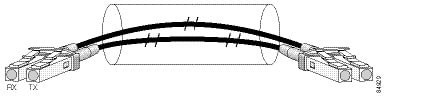
XFP Module Connections
The 10GLR, 10GER, and 10GZR XFP modules include an optical transmitter and receiver pair integrated with Clock and Data Recovery (CDR) integrated circuits. The XFP modules provide high-speed serial links at the rate of 10.3125 Gbps (10-Gigabit Ethernet LAN PHY mode) and 9.95328 Gbps (10-Gigabit Ethernet WAN PHY mode) on single-mode fibers (SMF). The transmit side recovers and retimes the 10-Gbps serial data and passes it to a laser driver. The laser driver biases and modulates a 1310-nm or 1550-nm laser, enabling data transmission over SMF through an LC connector. The receive side recovers and retimes the 10-Gbps optical data stream from a photo detector transimpedance amplifier and passes it to an output driver.
See the label on the XFP module for the technology type and model. Figure 2-64 shows an XFP module and Table 2-53 shows the XFP module specifications.
XFP Port Cabling Specifications
Table 2-54 shows the port cabling specifications for an XFP module.
|
|
|
|
|---|---|---|
 Feedback