Pseudowire Overview
The following sections provide an overview of pseudowire.
Circuit Emulation Overview
Circuit Emulation (CEM) is a technology that provides a protocol-independent transport over IP networks. It enables proprietary or legacy applications to be carried transparently to the destination, similar to a leased line.
The Cisco router supports two pseudowire types that utilize CEM transport: Structure-Agnostic TDM over Packet (SAToP) and Circuit Emulation Service over Packet-Switched Network (CESoPSN). The following sections provide an overview of these pseudowire types.
Structure-Agnostic TDM over Packet
SAToP encapsulates time division multiplexing (TDM) bit-streams (T1, E1, T3, E3) as PWs over public switched networks. It disregards any structure that may be imposed on streams, in particular the structure imposed by the standard TDM framing.
The protocol used for emulation of these services does not depend on the method in which attachment circuits are delivered to the provider edge (PE) devices. For example, a T1 attachment circuit is treated the same way for all delivery methods, including copper, multiplex in a T3 circuit, a virtual tributary of a SONET/SDH circuit, or unstructured Circuit Emulation Service (CES).
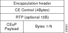
In SAToP mode the interface is considered as a continuous framed bit stream. The packetization of the stream is done according to IETF RFC 4553. All signaling is carried out transparently as a part of a bit stream. The figure below shows the frame format in Unstructured SAToP mode.

The table below shows the payload and jitter limits for the T1 lines in the SAToP frame format.
SAToP T1 Frame: Payload and Jitter Limits
|
Maximum Payload |
Maximum Jitter |
Minimum Jitter |
Minimum Payload |
Maximum Jitter |
Minimum Jitter |
|
960 |
320 |
10 |
192 |
64 |
2 |
The table below shows the payload and jitter limits for the E1 lines in the SAToP frame format.
SAToP E1 Frame: Payload and Jitter Limits
|
Maximum Payload |
Maximum Jitter |
Minimum Jitter |
Minimum Payload |
Maximum Jitter |
Minimum Jitter |
|
1280 |
320 |
10 |
256 |
64 |
2 |
For instructions on how to configure SAToP, see “Configuring Structure-Agnostic TDM over Packet” section on page 11-11.
Circuit Emulation Service over Packet-Switched Network
CESoPSN encapsulates structured TDM signals as PWs over public switched networks (PSNs). It complements similar work for structure-agnostic emulation of TDM bit streams, such as SAToP. Emulation of circuits saves PSN bandwidth and supports DS0-level grooming and distributed cross-connect applications. It also enhances resilience of CE devices due to the effects of loss of packets in the PSN.
CESoPSN identifies framing and sends only the payload, which can either be channelized T1s within DS3 or DS0s within T1. DS0s can be bundled to the same packet. The CESoPSN mode is based on IETF RFC 5086.
CESoPSN supports channel associated signaling (CAS) for E1 and T1 interfaces. CAS provides signaling information within each DS0 channel as opposed to using a separate signaling channel. CAS is also referred to as in-band signaling or robbed bit signaling.
Each supported interface can be configured individually to any supported mode. The supported services comply with IETF and ITU drafts and standards.
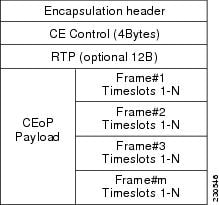
The figure below shows the frame format in CESoPSN mode.

The table below shows the payload and jitter for the DS0 lines in the CESoPSN mode.
CESoPSN DS0 Lines: Payload and Jitter Limits
|
DS0 |
Maximum Payload |
Maximum Jitter |
Minimum Jitter |
Minimum Payload |
Maximum Jitter |
Minimum Jitter |
|---|---|---|---|---|---|---|
|
1 |
40 |
320 |
10 |
32 |
256 |
8 |
|
2 |
80 |
320 |
10 |
32 |
128 |
4 |
|
3 |
120 |
320 |
10 |
33 |
128 |
4 |
|
4 |
160 |
320 |
10 |
32 |
64 |
2 |
|
5 |
200 |
320 |
10 |
40 |
64 |
2 |
|
6 |
240 |
320 |
10 |
48 |
64 |
2 |
|
7 |
280 |
320 |
10 |
56 |
64 |
2 |
|
8 |
320 |
320 |
10 |
64 |
64 |
2 |
|
9 |
360 |
320 |
10 |
72 |
64 |
2 |
|
10 |
400 |
320 |
10 |
80 |
64 |
2 |
|
11 |
440 |
320 |
10 |
88 |
64 |
2 |
|
12 |
480 |
320 |
10 |
96 |
64 |
2 |
|
13 |
520 |
320 |
10 |
104 |
64 |
2 |
|
14 |
560 |
320 |
10 |
112 |
64 |
2 |
|
15 |
600 |
320 |
10 |
120 |
64 |
2 |
|
16 |
640 |
320 |
10 |
128 |
64 |
2 |
|
17 |
680 |
320 |
10 |
136 |
64 |
2 |
|
18 |
720 |
320 |
10 |
144 |
64 |
2 |
|
19 |
760 |
320 |
10 |
152 |
64 |
2 |
|
20 |
800 |
320 |
10 |
160 |
64 |
2 |
|
21 |
840 |
320 |
10 |
168 |
64 |
2 |
|
22 |
880 |
320 |
10 |
176 |
64 |
2 |
|
23 |
920 |
320 |
10 |
184 |
64 |
2 |
|
24 |
960 |
320 |
10 |
192 |
64 |
2 |
|
25 |
1000 |
320 |
10 |
200 |
64 |
2 |
|
26 |
1040 |
320 |
10 |
208 |
64 |
2 |
|
27 |
1080 |
320 |
10 |
216 |
64 |
2 |
|
28 |
1120 |
320 |
10 |
224 |
64 |
2 |
|
29 |
1160 |
320 |
10 |
232 |
64 |
2 |
|
30 |
1200 |
320 |
10 |
240 |
64 |
2 |
|
31 |
1240 |
320 |
10 |
248 |
64 |
2 |
|
32 |
1280 |
320 |
10 |
256 |
64 |
2 |
For instructions on how to configure SAToP, see Configuring Structure-Agnostic TDM over Packet.
Transportation of Service Using Ethernet over MPLS
Ethernet over MPLS (EoMPLS) PWs provide a tunneling mechanism for Ethernet traffic through an MPLS-enabled Layer 3 core network. EoMPLS PWs encapsulate Ethernet protocol data units (PDUs) inside MPLS packets and use label switching to forward them across an MPLS network. EoMPLS PWs are an evolutionary technology that allows you to migrate packet networks from legacy networks while providing transport for legacy applications. EoMPLS PWs also simplify provisioning, since the provider edge equipment only requires Layer 2 connectivity to the connected customer edge (CE) equipment. The Cisco router implementation of EoMPLS PWs is compliant with the RFC 4447 and 4448 standards.
The Cisco router supports VLAN rewriting on EoMPLS PWs. If the two networks use different VLAN IDs, the router rewrites PW packets using the appropriate VLAN number for the local network.
For instructions on how to create an EoMPLS PW, see . Configuring an Ethernet over MPLS Pseudowire.

 Feedback