- Cisco BGP Overview
- Configuring a Basic BGP Network
- Connecting to a Service Provider Using External BGP
- Configuring BGP Neighbor Session Options
- Configuring Internal BGP Features
- Configuring Advanced BGP Features
- BGP Link Bandwidth
- iBGP Multipath Load Sharing
- BGP Multipath Load Sharing for Both eBGP and iBGP in an MPLS-VPN
- Loadsharing IP Packets Over More Than Six Parallel Paths
- BGP Policy Accounting
- BGP Policy Accounting Output Interface Accounting
- BGP Cost Community
- BGP Support for IP Prefix Import from Global Table into a VRF Table
- Per-VRF Assignment of BGP Router ID
- BGP Next Hop Unchanged
- Finding Feature Information
- Prerequisites for Configuring a Basic BGP Network
- Restrictions for Configuring a Basic BGP Network
- Information About Configuring a Basic BGP Network
- BGP Version 4
- BGP Router ID
- BGP-Speaker and Peer Relationships
- BGP Autonomous System Number Formats
- Cisco Implementation of 4-Byte Autonomous System Numbers
- BGP Peer Session Establishment
- Cisco Implementation of BGP Global and Address Family Configuration Commands
- BGP Session Reset
- BGP Route Aggregation
- BGP Aggregation Route AS-SET Information Generation
- Routing Policy Change Management
- Conditional BGP Route Injection
- BGP Peer Groups
- BGP Backdoor Routes
- Peer Groups and BGP Update Messages
- BGP Update Group
- BGP Dynamic Update Group Configuration
- BGP Peer Templates
- Inheritance in Peer Templates
- Peer Session Templates
- Peer Policy Templates
- BGP IPv6 Neighbor Activation Under the IPv4 Address Family
- How to Configure a Basic BGP Network
- Configuring a BGP Routing Process
- Configuring a BGP Peer
- Configuring a BGP Routing Process and Peers Using 4-Byte Autonomous System Numbers
- Modifying the Default Output and Regular Expression Match Format for 4-Byte Autonomous System Numbers
- Configuring a BGP Peer for the IPv4 VRF Address Family
- Customizing a BGP Peer
- Removing BGP Configuration Commands Using a Redistribution
- Monitoring and Maintaining Basic BGP
- Aggregating Route Prefixes Using BGP
- Originating BGP Routes
- Configuring a BGP Peer Group
- Configuring Peer Session Templates
- Configuring Peer Policy Templates
- Monitoring and Maintaining BGP Dynamic Update Groups
- Example Configuring a BGP Process and Customizing Peers
- Examples Configuring a BGP Routing Process and Peers Using 4-Byte Autonomous System Numbers
- Examples Configuring a VRF and Setting an Extended Community Using a BGP 4-Byte Autonomous System Number
- Example NLRI to AFI Configuration
- Examples Removing BGP Configuration Commands Using a Redistribution Example
- Examples BGP Soft Reset
- Example Resetting BGP Peers Using 4-Byte Autonomous System Numbers
- Example Resetting and Displaying Basic BGP Information
- Examples Aggregating Prefixes Using BGP
- Example Configuring a BGP Peer Group
- Example Configuring Peer Session Templates
- Example Configuring Peer Policy Templates
- Examples Monitoring and Maintaining BGP Dynamic Update Peer-Groups
Configuring a Basic BGP Network
This module describes the basic tasks to configure a basic Border Gateway Protocol (BGP) network. BGP is an interdomain routing protocol that is designed to provide loop-free routing between organizations. The Cisco IOS implementation of the neighbor and address family commands is explained. This module also contains tasks to configure and customize BGP peers, implement BGP route aggregation, configure BGP route origination, and define BGP backdoor routes. BGP peer group definition is documented, peer session templates are introduced, and update groups are explained,
- Finding Feature Information
- Prerequisites for Configuring a Basic BGP Network
- Restrictions for Configuring a Basic BGP Network
- Information About Configuring a Basic BGP Network
- How to Configure a Basic BGP Network
- Configuration Examples for a Basic BGP Network
- Where to Go Next
- Additional References
- Feature Information for Configuring a Basic BGP Network
Finding Feature Information
Your software release may not support all the features documented in this module. For the latest feature information and caveats, see the release notes for your platform and software release. To find information about the features documented in this module, and to see a list of the releases in which each feature is supported, see the Feature Information Table at the end of this document.
Use Cisco Feature Navigator to find information about platform support and Cisco software image support. To access Cisco Feature Navigator, go to www.cisco.com/go/cfn. An account on Cisco.com is not required.
Prerequisites for Configuring a Basic BGP Network
Before configuring a basic BGP network, you should be familiar with the "Cisco BGP Overview" module.
Restrictions for Configuring a Basic BGP Network
A router that runs Cisco IOS software can be configured to run only one BGP routing process and to be a member of only one BGP autonomous system. However, a BGP routing process and autonomous system can support multiple address family configurations.
Information About Configuring a Basic BGP Network
- BGP Version 4
- BGP Router ID
- BGP-Speaker and Peer Relationships
- BGP Autonomous System Number Formats
- Cisco Implementation of 4-Byte Autonomous System Numbers
- BGP Peer Session Establishment
- Cisco Implementation of BGP Global and Address Family Configuration Commands
- BGP Session Reset
- BGP Route Aggregation
- BGP Aggregation Route AS-SET Information Generation
- Routing Policy Change Management
- Conditional BGP Route Injection
- BGP Peer Groups
- BGP Backdoor Routes
- Peer Groups and BGP Update Messages
- BGP Update Group
- BGP Dynamic Update Group Configuration
- BGP Peer Templates
- Inheritance in Peer Templates
- Peer Session Templates
- Peer Policy Templates
- BGP IPv6 Neighbor Activation Under the IPv4 Address Family
BGP Version 4
Border Gateway Protocol (BGP) is an interdomain routing protocol designed to provide loop-free routing between separate routing domains that contain independent routing policies (autonomous systems). The Cisco IOSsoftware implementation of BGP version 4 includes multiprotocol extensions to allow BGP to carry routing information for IP multicast routes and multiple Layer 3 protocol address families including IP Version 4 (IPv4), IP Version 6 (IPv6), and Virtual Private Networks version 4 (VPNv4).
BGP is mainly used to connect a local network to an external network to gain access to the Internet or to connect to other organizations. When connecting to an external organization, external BGP (eBGP) peering sessions are created. Although BGP is referred to as an exterior gateway protocol (EGP) many networks within an organization are becoming so complex that BGP can be used to simplify the internal network used within the organization. BGP peers within the same organization exchange routing information through internal BGP (iBGP) peering sessions.
 Note |
BGP requires more configuration than other routing protocols, and the effects of any configuration changes must be fully understood. Incorrect configuration can create routing loops and negatively impact normal network operation. |
BGP Router ID
BGP uses a router ID to identify BGP-speaking peers. The BGP router ID is a 32-bit value that is often represented by an IPv4 address. By default, the Cisco IOS software sets the router ID to the IPv4 address of a loopback interface on the router. If no loopback interface is configured on the router, then the software chooses the highest IPv4 address configured to a physical interface on the router to represent the BGP router ID. The BGP router ID must be unique to the BGP peers in a network.
BGP-Speaker and Peer Relationships
A BGP-speaking router does not discover another BGP-speaking device automatically. A network administrator usually manually configures the relationships between BGP-speaking routers. A peer device is a BGP-speaking router that has an active TCP connection to another BGP-speaking device. This relationship between BGP devices is often referred to as a neighbor but, as this can imply the idea that the BGP devices are directly connected with no other router in between, the term neighbor will be avoided whenever possible in this document. A BGP speaker is the local router and a peer is any other BGP-speaking network device.
When a TCP connection is established between peers, each BGP peer initially exchanges all its routes--the complete BGP routing table--with the other peer. After this initial exchange only incremental updates are sent when there has been a topology change in the network, or when a routing policy has been implemented or modified. In the periods of inactivity between these updates, peers exchange special messages called keepalives.
A BGP autonomous system is a network controlled by a single technical administration entity. Peer routers are called external peers when they are in different autonomous systems and internal peers when they are in the same autonomous system. Usually, external peers are adjacent and share a subnet; internal peers may be anywhere in the same autonomous system.
For more details about external BGP peers, see the "Connecting to a Service Provider Using External BGP" module. For more details about internal BGP peers, see the "Configuring Internal BGP Features" module.
BGP Autonomous System Number Formats
Prior to January 2009, BGP autonomous system numbers that were allocated to companies were 2-octet numbers in the range from 1 to 65535 as described in RFC 4271, A Border Gateway Protocol 4 (BGP-4) . Due to increased demand for autonomous system numbers, the Internet Assigned Number Authority (IANA) will start in January 2009 to allocate four-octet autonomous system numbers in the range from 65536 to 4294967295. RFC 5396, Textual Representation of Autonomous System (AS) Numbers , documents three methods of representing autonomous system numbers. Cisco has implemented the following two methods:
- Asplain--Decimal value notation where both 2-byte and 4-byte autonomous system numbers are represented by their decimal value. For example, 65526 is a 2-byte autonomous system number and 234567 is a 4-byte autonomous system number.
- Asdot--Autonomous system dot notation where 2-byte autonomous system numbers are represented by their decimal value and 4-byte autonomous system numbers are represented by a dot notation. For example, 65526 is a 2-byte autonomous system number and 1.169031 is a 4-byte autonomous system number (this is dot notation for the 234567 decimal number).
For details about the third method of representing autonomous system numbers, see RFC 5396.
Asdot Only Autonomous System Number Formatting
In Cisco IOS Release 12.0(32)S12, 12.4(24)T, and later releases, the 4-octet (4-byte) autonomous system numbers are entered and displayed only in asdot notation, for example, 1.10 or 45000.64000. When using regular expressions to match 4-byte autonomous system numbers the asdot format includes a period which is a special character in regular expressions. A backslash must be entered before the period (for example, 1\.14) to ensure the regular expression match does not fail. The table below shows the format in which 2-byte and 4-byte autonomous system numbers are configured, matched in regular expressions, and displayed in show command output in Cisco IOS images where only asdot formatting is available.
| Table 1 | Asdot Only 4-Byte Autonomous System Number Format |
| Format |
Configuration Format |
Show Command Output and Regular Expression Match Format |
|---|---|---|
| asdot |
2-byte: 1 to 65535 4-byte: 1.0 to 65535.65535 |
2-byte: 1 to 65535 4-byte: 1.0 to 65535.65535 |
Asplain as Default Autonomous System Number Formatting
In Cisco IOS Release 12.0(32)SY8, 12.0(33)S3, 12.2(33)SRE, 12.2(33)XNE, 12.2(33)SXI1, and later releases, the Cisco implementation of 4-byte autonomous system numbers uses asplain as the default display format for autonomous system numbers, but you can configure 4-byte autonomous system numbers in both the asplain and asdot format. In addition, the default format for matching 4-byte autonomous system numbers in regular expressions is asplain, so you must ensure that any regular expressions to match 4-byte autonomous system numbers are written in the asplain format. If you want to change the default show command output to display 4-byte autonomous system numbers in the asdot format, use the bgp asnotation dot command under router configuration mode. When the asdot format is enabled as the default, any regular expressions to match 4-byte autonomous system numbers must be written using the asdot format, or the regular expression match will fail. The tables below show that although you can configure 4-byte autonomous system numbers in either asplain or asdot format, only one format is used to display show command output and control 4-byte autonomous system number matching for regular expressions, and the default is asplain format. To display 4-byte autonomous system numbers in show command output and to control matching for regular expressions in the asdot format, you must configure the bgp asnotation dot command. After enabling the bgp asnotation dot command, a hard reset must be initiated for all BGP sessions by entering the clear ip bgp * command.
Note |
If you are upgrading to an image that supports 4-byte autonomous system numbers, you can still use 2-byte autonomous system numbers. The show command output and regular expression match are not changed and remain in asplain (decimal value) format for 2-byte autonomous system numbers regardless of the format configured for 4-byte autonomous system numbers. |
| Table 2 | Default Asplain 4-Byte Autonomous System Number Format |
| Format |
Configuration Format |
Show Command Output and Regular Expression Match Format |
|---|---|---|
| asplain |
2-byte: 1 to 65535 4-byte: 65536 to 4294967295 |
2-byte: 1 to 65535 4-byte: 65536 to 4294967295 |
| asdot |
2-byte: 1 to 65535 4-byte: 1.0 to 65535.65535 |
2-byte: 1 to 65535 4-byte: 65536 to 4294967295 |
| Table 3 | Asdot 4-Byte Autonomous System Number Format |
| Format |
Configuration Format |
Show Command Output and Regular Expression Match Format |
|---|---|---|
| asplain |
2-byte: 1 to 65535 4-byte: 65536 to 4294967295 |
2-byte: 1 to 65535 4-byte: 1.0 to 65535.65535 |
| asdot |
2-byte: 1 to 65535 4-byte: 1.0 to 65535.65535 |
2-byte: 1 to 65535 4-byte: 1.0 to 65535.65535 |
Reserved and Private Autonomous System Numbers
In Cisco IOS Release 12.0(32)S12, 12.0(32)SY8, 12.0(33)S3, 12.2(33)SRE, 12.2(33)XNE, 12.2(33)SXI1, 12.4(24)T, and later releases, the Cisco implementation of BGP supports RFC 4893. RFC 4893 was developed to allow BGP to support a gradual transition from 2-byte autonomous system numbers to 4-byte autonomous system numbers. A new reserved (private) autonomous system number, 23456, was created by RFC 4893 and this number cannot be configured as an autonomous system number in the Cisco IOS CLI.
RFC 5398, Autonomous System (AS) Number Reservation for Documentation Use , describes new reserved autonomous system numbers for documentation purposes. Use of the reserved numbers allow configuration examples to be accurately documented and avoids conflict with production networks if these configurations are literally copied. The reserved numbers are documented in the IANA autonomous system number registry. Reserved 2-byte autonomous system numbers are in the contiguous block, 64496 to 64511 and reserved 4-byte autonomous system numbers are from 65536 to 65551 inclusive.
Private 2-byte autonomous system numbers are still valid in the range from 64512 to 65534 with 65535 being reserved for special use. Private autonomous system numbers can be used for internal routing domains but must be translated for traffic that is routed out to the Internet. BGP should not be configured to advertise private autonomous system numbers to external networks. Cisco IOS software does not remove private autonomous system numbers from routing updates by default. We recommend that ISPs filter private autonomous system numbers.
Note |
Autonomous system number assignment for public and private networks is governed by the IANA. For information about autonomous-system numbers, including reserved number assignment, or to apply to register an autonomous system number, see the following URL: http://www.iana.org/. |
Cisco Implementation of 4-Byte Autonomous System Numbers
In Cisco IOS Release 12.0(32)SY8, 12.0(33)S3, 12.2(33)SRE, 12.2(33)XNE, 12.2(33)SXI1, and later releases, the Cisco implementation of 4-byte autonomous system numbers uses asplain--65538 for example--as the default regular expression match and output display format for autonomous system numbers, but you can configure 4-byte autonomous system numbers in both the asplain format and the asdot format as described in RFC 5396. To change the default regular expression match and output display of 4-byte autonomous system numbers to asdot format, use the bgp asnotation dot command followed by the clear ip bgp * command to perform a hard reset of all current BGP sessions.
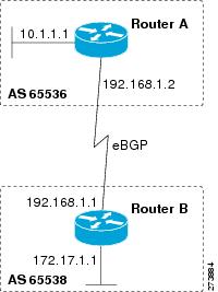
In Cisco IOS Release 12.0(32)S12, and 12.4(24)T, the Cisco implementation of 4-byte autonomous system numbers uses asdot--1.2 for example--as the only configuration format, regular expression match, and output display, with no asplain support. For an example of BGP peers in two autonomous systems using 4-byte numbers, see the figure below. To view a configuration example of the configuration between three neighbor peers in separate 4-byte autonomous systems configured using asdot notation, see the Examples Configuring a BGP Routing Process and Peers Using 4-Byte Autonomous System Numbers.
Cisco also supports RFC 4893, which was developed to allow BGP to support a gradual transition from 2-byte autonomous system numbers to 4-byte autonomous system numbers. To ensure a smooth transition, we recommend that all BGP speakers within an autonomous system that is identified using a 4-byte autonomous system number be upgraded to support 4-byte autonomous system numbers.
Note |
A new private autonomous system number, 23456, was created by RFC 4893, and this number cannot be configured as an autonomous system number in the Cisco IOS CLI. |
| Figure 1 | BGP Peers in Two Autonomous Systems Using 4-Byte Numbers |
BGP Peer Session Establishment
When a BGP routing process establishes a peering session with a peer it goes through the following state changes:
- Idle--Initial state the BGP routing process enters when the routing process is enabled or when the router is reset. In this state, the router waits for a start event, such as a peering configuration with a remote peer. After the router receives a TCP connection request from a remote peer, the router initiates another start event to wait for a timer before starting a TCP connection to a remote peer. If the router is reset then the peer is reset and the BGP routing process returns to the Idle state.
- Connect--The BGP routing process detects that a peer is trying to establish a TCP session with the local BGP speaker.
- Active--In this state, the BGP routing process tries to establish a TCP session with a peer router using the ConnectRetry timer. Start events are ignored while the BGP routing process is in the Active state. If the BGP routing process is reconfigured or if an error occurs, the BGP routing process will release system resources and return to an Idle state.
- OpenSent--The TCP connection is established and the BGP routing process sends an OPEN message to the remote peer, and transitions to the OpenSent state. The BGP routing process can receive other OPEN messages in this state. If the connection fails, the BGP routing process transitions to the Active state.
- OpenReceive--The BGP routing process receives the OPEN message from the remote peer and waits for an initial keepalive message from the remote peer. When a keepalive message is received, the BGP routing process transitions to the Established state. If a notification message is received, the BGP routing process transitions to the Idle state. If an error or configuration change occurs that affects the peering session, the BGP routing process sends a notification message with the Finite State Machine (FSM) error code and then transitions to the Idle state.
- Established--The initial keepalive is received from the remote peer. Peering is now established with the remote neighbor and the BGP routing process starts exchanging update message with the remote peer. The hold timer restarts when an update or keepalive message is received. If the BGP process receives an error notification, it will transition to the Idle state.
Cisco Implementation of BGP Global and Address Family Configuration Commands
The address family model for configuring BGP is based on splitting apart the configuration for each address family. All commands that are independent of the address family are grouped together at the beginning (highest level) of the configuration, and these are followed by separate submodes for commands specific to each address family (with the exception that commands relating to IPv4 unicast can also be entered at the beginning of the configuration). When a network operator configures BGP, the flow of BGP configuration categories is represented by the following bullets in order:
- Global configuration--Configuration that is applied to BGP in general, rather than to specific neighbors. For example, the network, redistribute, and bgp bestpath commands.
- Address family-dependent configuration--Configuration that applies to a specific address family such as policy on an individual neighbor.
The relationship between BGP global and BGP address family-dependent configuration categories is shown in the table below.
| Table 4 | Relationships Between BGP Configuration Categories |
| BGP Configuration Category |
Configuration Sets Within Category |
|---|---|
| Global address family-independent |
One set of global address family-independent configurations |
| Address family-dependent |
One set of global address family-dependent configurations per address family |
Note |
Address family configuration must be entered within the address family submode to which it applies. |
The following is an example of BGP configuration statements showing the grouping of global address family-independent and address family-dependent commands.
router bgp <AS>
 ! AF independent part
 neighbor <ip-address> <command> ! Session config; AF independent
 address-family ipv4 unicast
  ! AF dependant part
  neighbor <ip-address> <command> ! Policy config; AF dependant
  exit-address-family
 address-family ipv4 multicast
  ! AF dependant part
  neighbor <ip-address> <command> ! Policy config; AF dependant
  exit-address-family
 address-family ipv4 unicast vrf <vrf-name>
  ! VRF specific AS independent commands
  ! VRF specific AS dependant commands
  neighbor <ip-address> <command> ! Session config; AF independent
  neighbor <ip-address> <command> ! Policy config; AF dependant
  exit-address-family
The following example shows actual BGP commands that match the BGP configuration statements in the previous example:
router bgp 45000
 router-id 172.17.1.99
 bgp log-neighbor-changes
 neighbor 192.168.1.2 remote-as 40000
 neighbor 192.168.3.2 remote-as 50000
 address-family ipv4 unicast
  neighbor 192.168.1.2 activate
  network 172.17.1.0 mask 255.255.255.0
  exit-address-family
 address-family ipv4 multicast
  neighbor 192.168.3.2 activate
  neighbor 192.168.3.2 advertisement-interval 25
  network 172.16.1.0 mask 255.255.255.0
  exit-address-family
 address-family ipv4 vrf vpn1
  neighbor 192.168.3.2 activate
  network 172.21.1.0 mask 255.255.255.0
  exit-address-family
In Cisco IOS Releases 12.0(22)S, 12.2(15)T, and later releases, the bgp upgrade-cli command simplifies the migration of BGP networks and existing configurations from the network layer reachability information (NLRI) format to the address family format. Network operators can configure commands in the address family identifier (AFI) format and save these command configurations to existing NLRI formatted configurations. The BGP hybrid command-line interface (CLI) does not add support for complete AFI and NLRI integration because of the limitations of the NLRI format. For complete support of AFI commands and features, we recommend upgrading existing NLRI configurations with the bgp upgrade-cli command. For a configuration example of migrating BGP configurations from the NLRI format to the address family format, see .
BGP Session Reset
Whenever there is a change in the routing policy due to a configuration change, BGP peering sessions must be reset using the clear ip bgp command. Cisco IOS software support the following three mechanisms to reset BGP peering sessions:
- Hard reset--A hard reset tears down the specified peering sessions including the TCP connection and deletes routes coming from the specified peer.
- Soft reset--A soft reset uses stored prefix information to reconfigure and activate BGP routing tables without tearing down existing peering sessions. Soft reconfiguration uses stored update information, at the cost of additional memory for storing the updates, to allow you to apply new BGP policy without disrupting the network. Soft reconfiguration can be configured for inbound or outbound sessions.
- Dynamic inbound soft reset--The route refresh capability, as defined in RFC 2918, allows the local router to reset inbound routing tables dynamically by exchanging route refresh requests to supporting peers. The route refresh capability does not store update information locally for non disruptive policy changes. It instead relies on dynamic exchange with supporting peers. Route refresh must first be advertised through BGP capability negotiation between peers. All BGP routers must support the route refresh capability. To determine if a BGP router supports this capability, use the show ip bgp neighborscommand. The following message is displayed in the output when the router supports the route refresh capability:
Received route refresh capability from peer.
The bgp soft-reconfig-backup command was introduced to configure BGP to perform inbound soft reconfiguration for peers that do not support the route refresh capability. The configuration of this command allows you to configure BGP to store updates (soft reconfiguration) only as necessary. Peers that support the route refresh capability are unaffected by the configuration of this command.
BGP Route Aggregation
BGP peers store and exchange routing information and the amount of routing information increases as more BGP speakers are configured. The use of route aggregation reduces the amount of information involved. Aggregation is the process of combining the attributes of several different routes so that only a single route is advertised. Aggregate prefixes use the classless interdomain routing (CIDR) principle to combine contiguous networks into one classless set of IP addresses that can be summarized in routing tables. Fewer routes now need to be advertised.
Two methods are available in BGP to implement route aggregation. You can redistribute an aggregated route into BGP or you can use a form of conditional aggregation. Basic route redistribution involves creating an aggregate route and then redistributing the routes into BGP. Conditional aggregation involves creating an aggregate route and then advertising or suppressing the advertising of certain routes on the basis of route maps, autonomous system set path (AS-SET) information, or summary information.
The bgp suppress-inactive command configures BGP to not advertise inactive routes to any BGP peer. A BGP routing process can advertise routes that are not installed in the routing information database (RIB) to BGP peers by default. A route that is not installed into the RIB is an inactive route. Inactive route advertisement can occur, for example, when routes are advertised through common route aggregation. Inactive route advertisements can be suppressed to provide more consistent data forwarding.
BGP Aggregation Route AS-SET Information Generation
AS-SET information can be generated when BGP routes are aggregated using the aggregate-address command. The path advertised for such a route is an AS-SET consisting of all the elements, including the communities, contained in all the paths that are being summarized. If the AS-PATHs to be aggregated are identical, only the AS-PATH is advertised. The ATOMIC-AGGREGATE attribute, set by default for the aggregate-address command, is not added to the AS-SET.
Routing Policy Change Management
Routing policies for a peer include all the configurations for elements such as route map, distribute list, prefix list, and filter list that may impact inbound or outbound routing table updates. Whenever there is a change in the routing policy, the BGP session must be soft cleared, or soft reset, for the new policy to take effect. Performing inbound reset enables the new inbound policy configured on the router to take effect. Performing outbound reset causes the new local outbound policy configured on the router to take effect without resetting the BGP session. As a new set of updates is sent during outbound policy reset, a new inbound policy of the neighbor can also take effect. This means that after changing inbound policy you must do an inbound reset on the local router or an outbound reset on the peer router. Outbound policy changes require an outbound reset on the local router or an inbound reset on the peer router.
There are two types of reset: hard reset and soft reset. The table below lists their advantages and disadvantages.
| Table 5 | Advantages and Disadvantages of Hard and Soft Resets |
Once you have defined two routers to be BGP neighbors, they will form a BGP connection and exchange routing information. If you subsequently change a BGP filter, weight, distance, version, or timer, or make a similar configuration change, you must reset BGP connections for the configuration change to take effect.
A soft reset updates the routing table for inbound and outbound routing updates. Cisco IOS Release 12.1 and later releases support soft reset without any prior configuration. This soft reset allows the dynamic exchange of route refresh requests and routing information between BGP routers, and the subsequent readvertisement of the respective outbound routing table. There are two types of soft reset:
- When soft reset is used to generate inbound updates from a neighbor, it is called dynamic inbound soft reset.
- When soft reset is used to send a new set of updates to a neighbor, it is called outbound soft reset.
To use soft reset without preconfiguration, both BGP peers must support the soft route refresh capability, which is advertised in the OPEN message sent when the peers establish a TCP session. Routers running Cisco IOS releases prior to Release 12.1 do not support the route refresh capability and must clear the BGP session using the neighbor soft-reconfiguration router configuration command. Clearing the BGP session in this way will have a negative impact upon network operations and should be used only as a last resort.
Conditional BGP Route Injection
Routes that are advertised through the BGP are commonly aggregated to minimize the number of routes that are used and reduce the size of global routing tables. However, common route aggregation can obscure more specific routing information that is more accurate but not necessary to forward packets to their destinations. Routing accuracy is obscured by common route aggregation because a prefix that represents multiple addresses or hosts over a large topological area cannot be accurately reflected in a single route. Cisco IOS software provides several methods in which you can originate a prefix into BGP. The existing methods include redistribution and using the network or aggregate-address command. These methods assume the existence of more specific routing information (matching the route to be originated) in either the routing table or the BGP table.
BGP conditional route injection allows you to originate a prefix into a BGP routing table without the corresponding match. This feature allows more specific routes to be generated based on administrative policy or traffic engineering information in order to provide more specific control over the forwarding of packets to these more specific routes, which are injected into the BGP routing table only if the configured conditions are met. Enabling this feature will allow you to improve the accuracy of common route aggregation by conditionally injecting or replacing less specific prefixes with more specific prefixes. Only prefixes that are equal to or more specific than the original prefix may be injected. BGP conditional route injection is enabled with the bgp inject-map exist-mapcommand and uses two route maps (inject map and exist map) to install one (or more) more specific prefixes into a BGP routing table. The exist map specifies the prefixes that the BGP speaker will track. The inject map defines the prefixes that will be created and installed into the local BGP table.
BGP Peer Groups
Often, in a BGP network, many neighbors are configured with the same update policies (that is, the same outbound route maps, distribute lists, filter lists, update source, and so on). Neighbors with the same update policies can be grouped into BGP peer groups to simplify configuration and, more importantly, to make configuration updates more efficient. When you have many peers, this approach is highly recommended.
BGP Backdoor Routes
In a BGP network topology with two border routers using eBGP to communicate to a number of different autonomous systems, using eBGP to communicate between the two border routers may not be the most efficient routing method. In the figure below, Router B as a BGP speaker will receive a route to Router D through eBGP, but this route will traverse at least two autonomous systems. Router B and Router D are also connected through an Enhanced Interior Gateway Routing Protocol (EIGRP) network (any IGP can be used here) and this route has a shorter path. EIGRP routes, however, have a default administrative distance of 90 and eBGP routes have a default administrative distance of 20, so BGP will prefer the eBGP route. Changing the default administrative distances is not recommended because changing the administrative distance may lead to routing loops. To cause BGP to prefer the EIGRP route, you can use the network backdoor command. BGP treats the network specified by the network backdoor command as a locally assigned network, except that it does not advertise the specified network in BGP updates. In the figure below, this means that Router B will communicate to Router D using the shorter EIGRP route instead of the longer eBGP route.
| Figure 2 | BGP Backdoor Route Topology |

Peer Groups and BGP Update Messages
In Cisco IOS software releases prior to Release 12.0(24)S, 12.2(18)S, or 12.3(4)T, BGP update messages were grouped based on peer group configurations. This method of grouping neighbors for BGP update message generation reduced the amount of system processing resources needed to scan the routing table. This method, however, had the following limitations:
- All neighbors that shared peer group configuration also had to share outbound routing policies.
- All neighbors had to belong to the same peer group and address family. Neighbors configured in different address families could not belong to different peer groups.
These limitations existed to balance optimal update generation and replication against peer group configuration. These limitations could cause the network operator to configure smaller peer groups, which reduced the efficiency of update message generation and limited the scalability of neighbor configuration.
BGP Update Group
The introduction of the BGP (dynamic) update group in Cisco IOS Releases 12.0(24)S, 12.2(18)S, 12.3(4)T, or 12.2(27)SBC, provides a different type of BGP peer grouping from existing BGP peer groups. Existing peer groups are not affected but peers with the same outbound policy configured that are not members of a current peer group can be grouped into an update group. The members of this update group will use the same update generation engine. When BGP update groups are configured an algorithm dynamically calculates the BGP update group membership based on outbound policies. Optimal BGP update message generation occurs automatically and independently. BGP neighbor configuration is no longer restricted by outbound routing policies, and update groups can belong to different address families.
BGP Dynamic Update Group Configuration
In Cisco IOS Release 12.0(24)S, 12.2(18)S, 12.3(4)T, 12.2(27)SBC, and later releases, a new algorithm was introduced that dynamically calculates and optimizes update groups of neighbors that share the same outbound policies and can share the same update messages. No configuration is required to enable the BGP dynamic update group and the algorithm runs automatically. When a change to outbound policy occurs, the router automatically recalculates update group memberships and applies the changes by triggering an outbound soft reset after a 1-minute timer expires. This behavior is designed to provide the network operator with time to change the configuration if a mistake is made. You can manually enable an outbound soft reset before the timer expires by entering the clear ip bgp ip-address soft outcommand.
Note |
In Cisco IOS Release 12.0(22)S, 12.2(14)S, 12.3(2)T, and prior releases, the update group recalculation delay timer is set to 3 minutes. |
For the best optimization of BGP update group generation, we recommend that the network operator keeps outbound routing policy the same for neighbors that have similar outbound policies.
BGP Peer Templates
To address some of the limitations of peer groups such as configuration management, BGP peer templates were introduced to support the BGP update group configuration.
A peer template is a configuration pattern that can be applied to neighbors that share policies. Peer templates are reusable and support inheritance, which allows the network operator to group and apply distinct neighbor configurations for BGP neighbors that share policies. Peer templates also allow the network operator to define very complex configuration patterns through the capability of a peer template to inherit a configuration from another peer template.
There are two types of peer templates:
- Peer session templates are used to group and apply the configuration of general session commands that are common to all address family and NLRI configuration modes.
- Peer policy templates are used to group and apply the configuration of commands that are applied within specific address families and NLRI configuration modes.
Peer templates improve the flexibility and enhance the capability of neighbor configuration. Peer templates also provide an alternative to peer group configuration and overcome some limitations of peer groups. BGP peer routers using peer templates also benefit from automatic update group configuration. With the configuration of the BGP peer templates and the support of the BGP dynamic update peer groups, the network operator no longer needs to configure peer groups in BGP and the network can benefit from improved configuration flexibility and faster convergence.
Note |
A BGP neighbor cannot be configured to work with both peer groups and peer templates. A BGP neighbor can be configured to belong only to a peer group or to inherit policies from peer templates. |
The following restrictions apply to the peer policy templates:
- A peer policy template can directly or indirectly inherit up to eight peer policy templates.
- A BGP neighbor cannot be configured to work with both peer groups and peer templates. A BGP neighbor can be configured to belong only to a peer group or to inherit policies only from peer templates.
Inheritance in Peer Templates
The inheritance capability is a key component of peer template operation. Inheritance in a peer template is similar to node and tree structures commonly found in general computing, for example, file and directory trees. A peer template can directly or indirectly inherit the configuration from another peer template. The directly inherited peer template represents the tree in the structure. The indirectly inherited peer template represents a node in the tree. Because each node also supports inheritance, branches can be created that apply the configurations of all indirectly inherited peer templates within a chain back to the directly inherited peer template or the source of the tree. This structure eliminates the need to repeat configuration statements that are commonly reapplied to groups of neighbors because common configuration statements can be applied once and then indirectly inherited by peer templates that are applied to neighbor groups with common configurations. Configuration statements that are duplicated separately within a node and a tree are filtered out at the source of the tree by the directly inherited template. A directly inherited template will overwrite any indirectly inherited statements that are duplicated in the directly inherited template.
Inheritance expands the scalability and flexibility of neighbor configuration by allowing you to chain together peer templates configurations to create simple configurations that inherit common configuration statements or complex configurations that apply very specific configuration statements along with common inherited configurations. Specific details about configuring inheritance in peer session templates and peer policy templates are provided in the following sections.
When BGP neighbors use inherited peer templates it can be difficult to determine which policies are associated with a specific template. In Cisco IOS 12.0(25)S, 12.4(11)T, 12.2(33)SRB, 12.2(33)SB, and later releases, the detail keyword was added to the show ip bgp template peer-policy command to display the detailed configuration of local and inherited policies associated with a specific template.
Peer Session Templates
Peer session templates are used to group and apply the configuration of general session commands to groups of neighbors that share session configuration elements. General session commands that are common for neighbors that are configured in different address families can be configured within the same peer session template. Peer session templates are created and configured in peer session configuration mode. Only general session commands can be configured in a peer session template. The following general session commands are supported by peer session templates:
- description
- disable-connected-check
- ebgp-multihop
- exit peer-session
- inherit peer-session
- local-as
- password
- remote-as
- shutdown
- timers
- translate-update
- update-source
- version
General session commands can be configured once in a peer session template and then applied to many neighbors through the direct application of a peer session template or through indirect inheritance from a peer session template. The configuration of peer session templates simplifies the configuration of general session commands that are commonly applied to all neighbors within an autonomous system.
Peer session templates support direct and indirect inheritance. A peer can be configured with only one peer session template at a time, and that peer session template can contain only one indirectly inherited peer session template.
Note |
If you attempt to configure more than one inherit statement with a single peer session template, an error message will be displayed. |
This behavior allows a BGP neighbor to directly inherit only one session template and indirectly inherit up to seven additional peer session templates. This allows you to apply up to a maximum of eight peer session configurations to a neighbor: the configuration from the directly inherited peer session template and the configurations from up to seven indirectly inherited peer session templates. Inherited peer session configurations are evaluated first and applied starting with the last node in the branch and ending with the directly applied peer session template configuration at the source of the tree. The directly applied peer session template will have priority over inherited peer session template configurations. Any configuration statements that are duplicated in inherited peer session templates will be overwritten by the directly applied peer session template. So, if a general session command is reapplied with a different value, the subsequent value will have priority and overwrite the previous value that was configured in the indirectly inherited template. The following examples illustrate the use of this feature.
In the following example, the general session command remote-as 1 is applied in the peer session template named SESSION-TEMPLATE-ONE:
template peer-session SESSION-TEMPLATE-ONE
 remote-as 1
 exit peer-session
Peer session templates support only general session commands. BGP policy configuration commands that are configured only for a specific address family or NLRI configuration mode are configured with peer policy templates.
Peer Policy Templates
Peer policy templates are used to group and apply the configuration of commands that are applied within specific address families and NLRI configuration mode. Peer policy templates are created and configured in peer policy configuration mode. BGP policy commands that are configured for specific address families are configured in a peer policy template. The following BGP policy commands are supported by peer policy templates:
- advertisement-interval
- allowas-in
- as-override
- capability
- default-originate
- distribute-list
- dmzlink-bw
- exit-peer-policy
- filter-list
- inherit peer-policy
- maximum-prefix
- next-hop-self
- next-hop-unchanged
- prefix-list
- remove-private-as
- route-map
- route-reflector-client
- send-community
- send-label
- soft-reconfiguration
- unsuppress-map
- weight
Peer policy templates are used to configure BGP policy commands that are configured for neighbors that belong to specific address families. Like peer session templates, peer policy templates are configured once and then applied to many neighbors through the direct application of a peer policy template or through inheritance from peer policy templates. The configuration of peer policy templates simplifies the configuration of BGP policy commands that are applied to all neighbors within an autonomous system.
Like peer session templates, a peer policy template supports inheritance. However, there are minor differences. A directly applied peer policy template can directly or indirectly inherit configurations from up to seven peer policy templates. So, a total of eight peer policy templates can be applied to a neighbor or neighbor group. Inherited peer policy templates are configured with sequence numbers like route maps. An inherited peer policy template, like a route map, is evaluated starting with the inherit statement with the lowest sequence number and ending with the highest sequence number. However, there is a difference; a peer policy template will not collapse like a route map. Every sequence is evaluated, and if a BGP policy command is reapplied with a different value, it will overwrite any previous value from a lower sequence number.
The directly applied peer policy template and the inherit statement with the highest sequence number will always have priority and be applied last. Commands that are reapplied in subsequent peer templates will always overwrite the previous values. This behavior is designed to allow you to apply common policy configurations to large neighbor groups and specific policy configurations only to certain neighbors and neighbor groups without duplicating individual policy configuration commands.
Peer policy templates support only policy configuration commands. BGP policy configuration commands that are configured only for specific address families are configured with peer policy templates.
The configuration of peer policy templates simplifies and improves the flexibility of BGP configuration. A specific policy can be configured once and referenced many times. Because a peer policy supports up to eight levels of inheritance, very specific and very complex BGP policies can also be created.
BGP IPv6 Neighbor Activation Under the IPv4 Address Family
Prior to Cisco IOS Release 12.2(33)SRE4, by default, both IPv6 and IPv4 capability is exchanged with a BGP peer that has an IPv6 address. When an IPv6 peer is configured, that neighbor is automatically activated under the IPv4 unicast address family.
Beginning with Cisco IOS Release 12.2(33)SRE4, when a new IPv6 neighbor is being configured, it is no longer automatically activated under the IPv4 address family. You can manually activate the IPv6 neighbor under the IPv4 address family if, for example, you have a dual stack environment and want to send IPv6 and IPv4 prefixes.
If you do not want an existing IPv6 peer to be activated under the IPv4 address family, you can manually deactivate the peer with the no neighbor activate command. Until then, existing configurations that activate an IPv6 neighbor under the IPv4 unicast address family will continue to try to establish a session.
How to Configure a Basic BGP Network
Configuring a basic BGP network consists of a few required tasks and many optional tasks. A BGP routing process must be configured and BGP peers must be configured, preferably using the address family configuration model. If the BGP peers are part of a VPN network, the BGP peers must be configured using the IPv4 VRF address family task. The other tasks in the following list are optional:
- Configuring a BGP Routing Process
- Configuring a BGP Peer
- Configuring a BGP Routing Process and Peers Using 4-Byte Autonomous System Numbers
- Modifying the Default Output and Regular Expression Match Format for 4-Byte Autonomous System Numbers
- Configuring a BGP Peer for the IPv4 VRF Address Family
- Customizing a BGP Peer
- Removing BGP Configuration Commands Using a Redistribution
- Monitoring and Maintaining Basic BGP
- Aggregating Route Prefixes Using BGP
- Originating BGP Routes
- Configuring a BGP Peer Group
- Configuring Peer Session Templates
- Configuring Peer Policy Templates
- Monitoring and Maintaining BGP Dynamic Update Groups
Configuring a BGP Routing Process
Perform this task to configure a BGP routing process. You must perform the required steps at least once to enable BGP. The optional steps here allow you to configure additional features in your BGP network. Several of the features, such as logging neighbor resets and immediate reset of a peer when its link goes down, are enabled by default but are presented here to enhance your understanding of how your BGP network operates.
Note |
A router that runs Cisco IOS software can be configured to run only one BGP routing process and to be a member of only one BGP autonomous system. However, a BGP routing process and autonomous system can support multiple concurrent BGP address family and subaddress family configurations. |
The configuration in this task is done at Router A in the figure below and would need to be repeated with appropriate changes to the IP addresses (for example, at Router B) to fully achieve a BGP process between the two routers. No address family is configured here for the BGP routing process so routing information for the IPv4 unicast address family is advertised by default.
| Figure 3 | BGP Topology with Two Autonomous Systems |

DETAILED STEPS
| Command or Action | Purpose | |||
|---|---|---|---|---|
|
|
Example: Router> enable |
Enables privileged EXEC mode. |
||
|
|
Example: Router# configure terminal |
Enters global configuration mode. |
||
|
|
Example: Router(config)# router bgp 40000 |
Configures a BGP routing process, and enters router configuration mode for the specified routing process. |
||
|
|
Example: Router(config-router)# network 10.1.1.0 mask 255.255.255.0 |
(Optional) Specifies a network as local to this autonomous system and adds it to the BGP routing table. |
||
|
|
Example: Router(config-router)# bgp router-id 10.1.1.99 |
(Optional) Configures a fixed 32-bit router ID as the identifier of the local router running BGP.
|
||
|
|
Example: Router(config-router)# timers bgp 70 120 |
(Optional) Sets BGP network timers.
|
||
|
|
Example: Router(config-router)# bgp fast-external-fallover |
(Optional) Enables the automatic resetting of BGP sessions. |
||
|
|
Example: Router(config-router)# bgp log-neighbor-changes |
(Optional) Enables logging of BGP neighbor status changes (up or down) and neighbor resets. |
||
|
|
Example: Router(config-router)# end |
Exits router configuration mode and enters privileged EXEC mode. |
||
|
|
Example: Router# show ip bgp |
(Optional) Displays the entries in the BGP routing table.
|
Examples
The following sample output from the show ip bgp command shows the BGP routing table for Router A in the figure above after this task has been configured on Router A. You can see an entry for the network 10.1.1.0 that is local to this autonomous system.
BGP table version is 12, local router ID is 10.1.1.99
Status codes: s suppressed, d damped, h history, * valid, > best, i - internal,
              r RIB-failure, S Stale
Origin codes: i - IGP, e - EGP, ? - incomplete
   Network          Next Hop            Metric LocPrf Weight Path
*> 10.1.1.0/24      0.0.0.0                  0         32768 i
Troubleshooting Tips
Use the ping command to check basic network connectivity between the BGP routers.
Configuring a BGP Peer
Perform this task to configure BGP between two IPv4 routers (peers). The address family configured here is the default IPv4 unicast address family and the configuration is done at Router A in the figure above. Remember to perform this task for any neighbor routers that are to be BGP peers.
Before you perform this task, perform the Configuring a BGP Routing Process task.
Note |
By default, neighbors that are defined using the neighbor remote-as command in router configuration mode exchange only IPv4 unicast address prefixes. To exchange other address prefix types, such as IPv6 prefixes, neighbors must also be activated using the neighbor activate command in address family configuration mode for the other prefix types, such as IPv6 prefixes. > |
DETAILED STEPS
| Command or Action | Purpose | |||
|---|---|---|---|---|
|
|
Example: Router> enable |
Enables privileged EXEC mode. |
||
|
|
Example: Router# configure terminal |
Enters global configuration mode. |
||
|
|
Example: Router(config)# router bgp 40000 |
Enters router configuration mode for the specified routing process. |
||
|
|
Example: Router(config-router)# neighbor 192.168.1.1 remote-as 45000 |
Adds the IP address of the neighbor in the specified autonomous system to the IPv4 multiprotocol BGP neighbor table of the local router. |
||
|
|
Example: Router(config-router)# address-family ipv4 unicast |
Specifies the IPv4 address family and enters address family configuration mode.
|
||
|
|
Example: Router(config-router-af)# neighbor 192.168.1.1 activate |
Enables the neighbor to exchange prefixes for the IPv4 unicast address family with the local router. |
||
|
|
Example: Router(config-router-af)# end |
Exits address family configuration mode and enters privileged EXEC mode. |
||
|
|
Example: Router# show ip bgp |
(Optional) Displays the entries in the BGP routing table.
|
||
|
|
Example: Router(config-router-af)# show ip bgp neighbors 192.168.2.2 |
(Optional) Displays information about the TCP and BGP connections to neighbors.
|
Examples
The following sample output from the show ip bgp command shows the BGP routing table for Router A in the figure above after this task has been configured on Router A and Router B. You can now see an entry for the network 172.17.1.0 in autonomous system 45000.
BGP table version is 13, local router ID is 10.1.1.99
Status codes: s suppressed, d damped, h history, * valid, > best, i - internal,
              r RIB-failure, S Stale
Origin codes: i - IGP, e - EGP, ? - incomplete
   Network          Next Hop            Metric LocPrf Weight Path
*> 10.1.1.0/24      0.0.0.0                  0         32768 i
*> 172.17.1.0/24    192.168.1.1              0             0 45000 i
The following sample output from the show ip bgp neighbors command shows information about the TCP and BGP connections to the BGP neighbor 192.168.1.1 of Router A in the figure above after this task has been configured on Router A:
BGP neighbor is 192.168.1.1,  remote AS 45000, external link
  BGP version 4, remote router ID 172.17.1.99
  BGP state = Established, up for 00:06:55
  Last read 00:00:15, last write 00:00:15, hold time is 120, keepalive intervals
  Configured hold time is 120,keepalive interval is 70 seconds, Minimum holdtims
  Neighbor capabilities:
    Route refresh: advertised and received (old & new)
    Address family IPv4 Unicast: advertised and received
  Message statistics:
    InQ depth is 0
    OutQ depth is 0
                         Sent       Rcvd
    Opens:                  1          1
    Notifications:          0          0
    Updates:                1          2
    Keepalives:            13         13
    Route Refresh:          0          0
    Total:                 15         16
  Default minimum time between advertisement runs is 30 seconds
 For address family: IPv4 Unicast
  BGP table version 13, neighbor version 13/0
 Output queue size : 0
  Index 1, Offset 0, Mask 0x2
  1 update-group member
                                 Sent       Rcvd
  Prefix activity:               ----       ----
    Prefixes Current:               1          1 (Consumes 52 bytes)
    Prefixes Total:                 1          1
    Implicit Withdraw:              0          0
    Explicit Withdraw:              0          0
    Used as bestpath:             n/a          1
    Used as multipath:            n/a          0
                                   Outbound    Inbound
  Local Policy Denied Prefixes:    --------    -------
    AS_PATH loop:                       n/a          1
    Bestpath from this peer:              1        n/a
    Total:                                1          1
  Number of NLRIs in the update sent: max 0, min 0
  Connections established 1; dropped 0
  Last reset never
Connection state is ESTAB, I/O status: 1, unread input bytes: 0
Connection is ECN Disabled
Local host: 192.168.1.2, Local port: 179
Foreign host: 192.168.1.1, Foreign port: 37725
Enqueued packets for retransmit: 0, input: 0  mis-ordered: 0 (0 bytes)
Event Timers (current time is 0x12F4F2C):
Timer          Starts    Wakeups            Next
Retrans            14          0             0x0
TimeWait            0          0             0x0
AckHold            13          8             0x0
SendWnd             0          0             0x0
KeepAlive           0          0             0x0
GiveUp              0          0             0x0
PmtuAger            0          0             0x0
DeadWait            0          0             0x0
iss:  165379618  snduna:  165379963  sndnxt:  165379963     sndwnd:  16040
irs: 3127821601  rcvnxt: 3127821993  rcvwnd:      15993  delrcvwnd:    391
SRTT: 254 ms, RTTO: 619 ms, RTV: 365 ms, KRTT: 0 ms
minRTT: 12 ms, maxRTT: 300 ms, ACK hold: 200 ms
Flags: passive open, nagle, gen tcbs
IP Precedence value : 6
Datagrams (max data segment is 1460 bytes):
Rcvd: 20 (out of order: 0), with data: 15, total data bytes: 391
Sent: 22 (retransmit: 0, fastretransmit: 0, partialack: 0, Second Congestion: 04
Troubleshooting Tips
Use the ping command to verify basic network connectivity between the BGP routers.
What to Do Next
If you have BGP peers in a VPN, proceed to theConfiguring a BGP Peer for the IPv4 VRF Address Family. If you do not have BGP peers in a VPN, proceed to the Customizing a BGP Peer.
Configuring a BGP Routing Process and Peers Using 4-Byte Autonomous System Numbers
Perform this task to configure a BGP routing process and BGP peers when the BGP peers are located in 4-byte autonomous system numbers. The address family configured here is the default IPv4 unicast address family, and the configuration is done at Router B in the figure above (in the "Cisco Implementation of 4-Byte Autonomous System Numbers" section). The 4-byte autonomous system numbers in this task are formatted in the default asplain (decimal value) format; for example, Router B is in autonomous system number 65538 in the figure above. Remember to perform this task for any neighbor routers that are to be BGP peers.
For more details about 4-byte autonomous system number formats, see the BGP Autonomous System Number Formats and the Cisco Implementation of 4-Byte Autonomous System Numbers.
This task requires Cisco IOS Release 12.0(32)SY8, 12.2(33)SXI1, or a later release to be running on the router.
Note |
By default, neighbors that are defined using the neighbor remote-as command in router configuration mode exchange only IPv4 unicast address prefixes. To exchange other address prefix types, such as IPv6 prefixes, neighbors must also be activated using the neighbor activate command in address family configuration mode for the other prefix types. > |
DETAILED STEPS
| Command or Action | Purpose | |||
|---|---|---|---|---|
|
|
Example: Router> enable |
Enables privileged EXEC mode. |
||
|
|
Example: Router# configure terminal |
Enters global configuration mode. |
||
|
|
Example: Router(config)# router bgp 65538 |
Enters router configuration mode for the specified routing process. |
||
|
|
Example: Router(config-router)# neighbor 192.168.1.2 remote-as 65536 |
Adds the IP address of the neighbor in the specified autonomous system to the IPv4 multiprotocol BGP neighbor table of the local router. |
||
|
|
|
-- |
||
|
|
Example: Router(config-router)# address-family ipv4 unicast |
Specifies the IPv4 address family and enters address family configuration mode.
|
||
|
|
Example: Router(config-router-af)# neighbor 192.168.1.2 activate |
Enables the neighbor to exchange prefixes for the IPv4 unicast address family with the local router. |
||
|
|
|
-- |
||
|
|
Example: Router(config-router)# network 172.17.1.0 mask 255.255.255.0 |
(Optional) Specifies a network as local to this autonomous system and adds it to the BGP routing table. |
||
|
|
Example: Router(config-router-af)# end |
Exits address family configuration mode and returns to privileged EXEC mode. |
||
|
|
Example: Router# show ip bgp 10.1.1.0 |
(Optional) Displays the entries in the BGP routing table.
|
||
|
|
Example: Router# show ip bgp summary |
(Optional) Displays the status of all BGP connections. |
Examples
The following output from the show ip bgp command at Router B shows the BGP routing table entry for network 10.1.1.0 learned from the BGP neighbor at 192.168.1.2 in Router A in the figure above with its 4-byte autonomous system number of 65536 displayed in the default asplain format.
RouterB# show ip bgp 10.1.1.0
BGP routing table entry for 10.1.1.0/24, version 2
Paths: (1 available, best #1)
  Advertised to update-groups:
     2
  65536
    192.168.1.2 from 192.168.1.2 (10.1.1.99)
      Origin IGP, metric 0, localpref 100, valid, external, best
The following output from the show ip bgp summary command shows the 4-byte autonomous system number 65536 for the BGP neighbor 192.168.1.2 of Router A in the figure above after this task has been configured on Router B:
RouterB# show ip bgp summary
BGP router identifier 172.17.1.99, local AS number 65538
BGP table version is 3, main routing table version 3
2 network entries using 234 bytes of memory
2 path entries using 104 bytes of memory
3/2 BGP path/bestpath attribute entries using 444 bytes of memory
1 BGP AS-PATH entries using 24 bytes of memory
0 BGP route-map cache entries using 0 bytes of memory
0 BGP filter-list cache entries using 0 bytes of memory
BGP using 806 total bytes of memory
BGP activity 2/0 prefixes, 2/0 paths, scan interval 60 secs
Neighbor        V          AS MsgRcvd MsgSent   TblVer  InQ OutQ  Up/Down  Stated
192.168.1.2     4       65536       6       6        3    0    0 00:01:33       1
Troubleshooting Tips
Use the ping command to verify basic network connectivity between the BGP routers.
Modifying the Default Output and Regular Expression Match Format for 4-Byte Autonomous System Numbers
Perform this task to modify the default output format for 4-byte autonomous system numbers from asplain format to asdot notation format. The show ip bgp summary command is used to display the changes in output format for the 4-byte autonomous system numbers.
For more details about 4-byte autonomous system number formats, see the BGP Autonomous System Number Formats.
This example requires Cisco IOS Release 12.0(32)SY8, 12.0(33)S3, 12.2(33)SRE, 12.2(33)XNE, 12.2(33)SXI1, or a later release, to be running on the router.
DETAILED STEPS
| Command or Action | Purpose | |||
|---|---|---|---|---|
|
|
Example: Router> enable |
Enables privileged EXEC mode. |
||
|
|
Example: Router# show ip bgp summary |
Displays the status of all BGP connections. |
||
|
|
Example: Router# configure terminal |
Enters global configuration mode. |
||
|
|
Example: Router(config)# router bgp 65538 |
Enters router configuration mode for the specified routing process. |
||
|
|
Example: Router(config-router)# bgp asnotation dot |
Changes the default output format of BGP 4-byte autonomous system numbers from asplain (decimal values) to dot notation.
|
||
|
|
Example: Router(config-router)# end |
Exits address family configuration mode and returns to privileged EXEC mode. |
||
|
|
Example: Router# clear ip bgp * |
Clears and resets all current BGP sessions.
|
||
|
|
Example: Router# show ip bgp summary |
Displays the status of all BGP connections. |
||
|
|
Example: Router# show ip bgp regexp ^1\.0$ |
Displays routes that match the autonomous system path regular expression. |
||
|
|
Example: Router# configure terminal |
Enters global configuration mode. |
||
|
|
Example: Router(config)# router bgp 65538 |
Enters router configuration mode for the specified routing process. |
||
|
|
Example: Router(config-router)# no bgp asnotation dot |
Resets the default output format of BGP 4-byte autonomous system numbers back to asplain (decimal values).
|
||
|
|
Example: Router(config-router)# end |
Exits router configuration mode and returns to privileged EXEC mode. |
||
|
|
Example: Router# clear ip bgp * |
Clears and resets all current BGP sessions.
|
Examples
The following output from the show ip bgp summary command shows the default asplain format of the 4-byte autonomous system numbers. Note the asplain format of the 4-byte autonomous system numbers, 65536 and 65550.
Router# show ip bgp summary
BGP router identifier 172.17.1.99, local AS number 65538
BGP table version is 1, main routing table version 1
Neighbor        V           AS MsgRcvd MsgSent   TblVer  InQ OutQ Up/Down  Statd
192.168.1.2     4       65536       7       7        1    0    0 00:03:04      0
192.168.3.2     4       65550       4       4        1    0    0 00:00:15      0
After the bgp asnotation dot command is configured (followed by the clear ip bgp * command to perform a hard reset of all current BGP sessions), the output is converted to asdot notation format as shown in the following output from the show ip bgp summary command. Note the asdot format of the 4-byte autonomous system numbers, 1.0 and 1.14 (these are the asdot conversions of the 65536 and 65550 autonomous system numbers.
Router# show ip bgp summary
BGP router identifier 172.17.1.99, local AS number 1.2
BGP table version is 1, main routing table version 1
Neighbor        V           AS MsgRcvd MsgSent   TblVer  InQ OutQ Up/Down  Statd
192.168.1.2     4         1.0       9       9        1    0    0 00:04:13      0
192.168.3.2     4        1.14       6       6        1    0    0 00:01:24      0
After the bgp asnotation dot command is configured (followed by the clear ip bgp * command to perform a hard reset of all current BGP sessions), the regular expression match format for 4-byte autonomous system paths is changed to asdot notation format. Although a 4-byte autonomous system number can be configured in a regular expression using either asplain format or asdot format, only 4-byte autonomous system numbers configured using the current default format are matched. In the first example below, the show ip bgp regexpcommand is configured with a 4-byte autonomous system number in asplain format. The match fails because the default format is currently asdot format and there is no output. In the second example using asdot format, the match passes and the information about the 4-byte autonomous system path is shown using the asdot notation.
Note |
The asdot notation uses a period which is a special character in Cisco regular expressions. To remove the special meaning, use a backslash before the period. |
Router# show ip bgp regexp ^65536$
Router# show ip bgp regexp ^1\.0$
BGP table version is 2, local router ID is 172.17.1.99
Status codes: s suppressed, d damped, h history, * valid, > best, i - internal,
              r RIB-failure, S Stale
Origin codes: i - IGP, e - EGP, ? - incomplete
   Network          Next Hop            Metric LocPrf Weight Path
*> 10.1.1.0/24      192.168.1.2              0             0 1.0 i
Configuring a BGP Peer for the IPv4 VRF Address Family
Perform this optional task to configure BGP between two IPv4 routers (peers) that must exchange IPv4 VRF information because they exist in a VPN. The address family configured here is the IPv4 VRF address family and the configuration is done at Router B in the figure below with the neighbor 192.168.3.2 at Router E in autonomous system 50000. Remember to perform this task for any neighbor routers that are to be BGP IPv4 VRF address family peers.
This task does not show the complete configuration required for VPN routing. For some complete example configurations and an example configuration showing how to create a VRF with a route-target that uses a 4-byte autonomous system number, see .
| Figure 4 | BGP Topology for IPv4 VRF Address Family |

Before you perform this task, perform the Configuring a BGP Routing Process task.
DETAILED STEPS
| Command or Action | Purpose | |
|---|---|---|
|
|
Example: Router> enable |
Enables privileged EXEC mode. |
|
|
Example: Router# configure terminal |
Enters global configuration mode. |
|
|
Example: Router(config)# ip vrf vpn1 |
Configures a VRF routing table and enters VRF configuration mode. |
|
|
Example: Router(config-vrf)# rd 45000:5 |
Creates routing and forwarding tables and specifies the default route distinguisher for a VPN. |
|
|
Example: Router(config-vrf)# route-target both 45000:100 |
Creates a route target extended community for a VRF.
|
|
|
Example: Router(config-vrf)# exit |
Exits VRF configuration mode and enters global configuration mode. |
|
|
Example: Router(config)# router bgp 45000 |
Enters router configuration mode for the specified routing process. |
|
|
Example: Router(config-router)# address-family ipv4 vrf vpn1 |
Specifies the IPv4 address family and enters address family configuration mode.
|
|
|
Example: Router(config-router-af)# neighbor 192.168.3.2 remote-as 45000 |
Adds the IP address of the neighbor in the specified autonomous system to the IPv4 multiprotocol BGP neighbor table of the local router. |
|
|
Example: Router(config-router-af)# neighbor 192.168.3.2 maximum-prefix 10000 warning-only |
Controls how many prefixes can be received from a neighbor.
|
|
|
Example: Router(config-router-af)# neighbor 192.168.3.2 activate |
Enables the neighbor to exchange prefixes for the IPv4 VRF address family with the local router. |
|
|
Example: Router(config-router-af)# end |
Exits address family configuration mode and enters privileged EXEC mode. |
Troubleshooting Tips
Use the ping command to verify basic network connectivity between the BGP routers, and use the show ip vrf command to verify that the VRF instance has been created.
Customizing a BGP Peer
Perform this task to customize your BGP peers. Although many of the steps in this task are optional, this task demonstrates how the neighbor and address family configuration command relationships work. Using the example of the IPv4 multicast address family, neighbor address family-independent commands are configured before the IPv4 multicast address family is configured. Commands that are address family-dependent are then configured and the exit address-family command is shown. An optional step shows how to disable a neighbor.
The configuration in this task is done at Router B in the figure below and would need to be repeated with appropriate changes to the IP addresses, for example, at Router E to fully configure a BGP process between the two routers.
| Figure 5 | BGP Peer Topology |

Note |
By default, neighbors that are defined using the neighbor remote-as command in router configuration mode exchange only IPv4 unicast address prefixes. To exchange other address prefix types, such as IPv6 prefixes, neighbors must also be activated using the neighbor activate command in address family configuration mode for the other prefix types, such as IPv6 prefixes. > |
DETAILED STEPS
| Command or Action | Purpose | |||
|---|---|---|---|---|
|
|
Example: Router> enable |
Enables privileged EXEC mode. |
||
|
|
Example: Router# configure terminal |
Enters global configuration mode. |
||
|
|
Example: Router(config)# router bgp 45000 |
Enters router configuration mode for the specified routing process. |
||
|
|
Example: Router(config-router)# no bgp default ipv4-unicast |
Disables the IPv4 unicast address family for the BGP routing process.
|
||
|
|
Example: Router(config-router)# neighbor 192.168.3.2 remote-as 50000 |
Adds the IP address of the neighbor in the specified autonomous system to the IPv4 multiprotocol BGP neighbor table of the local router. |
||
|
|
Example: Router(config-router)# neighbor 192.168.3.2 description finance |
(Optional) Associates a text description with the specified neighbor. |
||
|
|
Example: Router(config-router)# address-family ipv4 multicast |
Specifies the IPv4 address family and enters address family configuration mode.
|
||
|
|
Example: Router(config-router-af)# network 172.17.1.0 mask 255.255.255.0 |
(Optional) Specifies a network as local to this autonomous system and adds it to the BGP routing table. |
||
|
|
Example: Router(config-router-af)# neighbor 192.168.3.2 activate |
Enables the exchange of information with a BGP neighbor. |
||
|
|
Example: Router(config-router-af)# neighbor 192.168.3.2 advertisement-interval 25 |
(Optional) Sets the minimum interval between the sending of BGP routing updates. |
||
|
|
Example: Router(config-router-af)# neighbor 192.168.3.2 default-originate |
(Optional) Permits a BGP speaker--the local router--to send the default route 0.0.0.0 to a peer for use as a default route. |
||
|
|
Example: Router(config-router-af)# exit-address-family |
Exits address family configuration mode and enters router configuration mode. |
||
|
|
Example: Router(config-router)# neighbor 192.168.3.2 shutdown |
(Optional) Disables a BGP peer or peer group.
|
||
|
|
Example: Router(config-router)# end |
Exits router configuration mode and enters privileged EXEC mode. |
||
|
|
Example: Router# show ip bgp ipv4 multicast |
(Optional) Displays IPv4 multicast database-related information. |
||
|
|
Example: Router# show ip bgp neighbors 192.168.3.2 |
(Optional) Displays information about the TCP and BGP connections to neighbors. |
Examples
The following sample output from the show ip bgp ipv4 multicast command shows BGP IPv4 multicast information for Router B in the figure above after this task has been configured on Router B and Router E. Note that the networks local to each router that were configured under IPv4 multicast address family appear in the output table.
BGP table version is 3, local router ID is 172.17.1.99
Status codes: s suppressed, d damped, h history, * valid, > best, i - internal,
              r RIB-failure, S Stale
Origin codes: i - IGP, e - EGP, ? - incomplete
   Network          Next Hop            Metric LocPrf Weight Path
*> 10.2.2.0/24      192.168.3.2              0             0 50000 i
*> 172.17.1.0/24    0.0.0.0                  0         32768 i
The following partial sample output from the show ip bgp neighborscommand for neighbor 192.168.3.2 shows general BGP information and specific BGP IPv4 multicast address family information about the neighbor. The command was entered on Router B in the figure above after this task had been configured on Router B and Router E.
BGP neighbor is 192.168.3.2,  remote AS 50000, external link
 Description: finance
  BGP version 4, remote router ID 10.2.2.99
  BGP state = Established, up for 01:48:27
  Last read 00:00:26, last write 00:00:26, hold time is 120, keepalive intervals
  Configured hold time is 120,keepalive interval is 70 seconds, Minimum holdtims
  Neighbor capabilities:
    Route refresh: advertised and received (old & new)
    Address family IPv4 Unicast: advertised
    Address family IPv4 Multicast: advertised and received
!
 For address family: IPv4 Multicast
  BGP table version 3, neighbor version 3/0
 Output queue size : 0
  Index 1, Offset 0, Mask 0x2
  1 update-group member
    Uses NEXT_HOP attribute for MBGP NLRIs
                                 Sent       Rcvd
  Prefix activity:               ----       ----
    Prefixes Current:               1          1 (Consumes 48 bytes)
    Prefixes Total:                 1          1
    Implicit Withdraw:              0          0
    Explicit Withdraw:              0          0
    Used as bestpath:             n/a          1
    Used as multipath:            n/a          0
                                   Outbound    Inbound
  Local Policy Denied Prefixes:    --------    -------
    Bestpath from this peer:              1        n/a
    Total:                                1          0
  Number of NLRIs in the update sent: max 0, min 0
  Minimum time between advertisement runs is 25 seconds
  Connections established 8; dropped 7
  Last reset 01:48:54, due to User reset
Connection state is ESTAB, I/O status: 1, unread input bytes: 0
Connection is ECN Disabled
Local host: 192.168.3.1, Local port: 13172
Foreign host: 192.168.3.2, Foreign port: 179
!
Removing BGP Configuration Commands Using a Redistribution
BGP CLI configuration can become quite complex even in smaller BGP networks. If you need to remove any CLI configuration, you must consider all the implications of removing the CLI. Analyze the current running configuration to determine the current BGP neighbor relationships, any address family considerations, and even other routing protocols that are configured. Many BGP CLI commands affect other parts of the CLI configuration.
Perform this task to remove all the BGP configuration commands used in a redistribution of BGP routes into EIGRP. A route map can be used to match and set parameters or to filter the redistributed routes to ensure that routing loops are not created when these routes are subsequently advertised by EIGRP. When removing BGP configuration commands you must remember to remove or disable all the related commands. In this example, if the route-map command is omitted, then the redistribution will still occur and possibly with unexpected results as the route map filtering has been removed. Omitting just the redistribute command would mean that the route map is not applied, but it would leave unused commands in the running configuration.
For more details on BGP CLI removal, see the "BGP CLI Removal Considerations" concept in the "Cisco BGP Overview" module.
To view the redistribution configuration before and after the CLI removal, see the Examples Removing BGP Configuration Commands Using a Redistribution Example.
DETAILED STEPS
| Command or Action | Purpose | |||||
|---|---|---|---|---|---|---|
|
|
Example: Router> enable |
Enables privileged EXEC mode. |
||||
|
|
Example: Router# configure terminal |
Enters global configuration mode. |
||||
|
|
Example: Router(config)# no route-map bgp-to-eigrp |
Removes a route map from the running configuration. |
||||
|
|
Example: Router(config)# router eigrp 100 |
Enters router configuration mode for the specified routing process. |
||||
|
|
Example: Router(config-router)# no redistribute bgp 45000 |
Disables the redistribution of routes from one routing domain into another routing domain.
|
||||
|
|
Example: Router(config-router)# end |
Exits router configuration mode and enters privileged EXEC mode. |
||||
|
|
Example: Router# show running-config |
(Optional) Displays the current running configuration on the router. |
Monitoring and Maintaining Basic BGP
The tasks in this section are concerned with the resetting and display of information about basic BGP processes and peer relationships. Once you have defined two routers to be BGP neighbors, they will form a BGP connection and exchange routing information. If you subsequently change a BGP filter, weight, distance, version, or timer, or make a similar configuration change, you may have to reset BGP connections for the configuration change to take effect.
- Configuring Inbound Soft-Reconfiguration When Route Refresh Capability Is Missing
- Resetting and Displaying Basic BGP Information
Configuring Inbound Soft-Reconfiguration When Route Refresh Capability Is Missing
Perform this task to configure inbound soft reconfiguration using the bgp soft-reconfig-backup command for BGP peers that do not support the route refresh capability. BGP Peers that support the route refresh capability are unaffected by the configuration of this command.
DETAILED STEPS
| Command or Action | Purpose | |||
|---|---|---|---|---|
|
|
Example: Router> enable |
Enables privileged EXEC mode. |
||
|
|
Example: Router# configure terminal |
Enters global configuration mode. |
||
|
|
Example: Router(config)# router bgp 45000 |
Enters router configuration mode for the specified routing process. |
||
|
|
Example: Router(config-router)# bgp log-neighbor-changes |
Enables logging of BGP neighbor resets. |
||
|
|
Example: Router(config-router)# bgp soft-reconfig-backup |
Configures a BGP speaker to perform inbound soft reconfiguration for peers that do not support the route refresh capability.
|
||
|
|
Example: Router(config-router)# neighbor 192.168.1.2 remote-as 40000 |
Adds the IP address of the neighbor in the specified autonomous system to the IPv4 multiprotocol BGP neighbor table of the local router. |
||
|
|
Example: Router(config-router)# neighbor 192.168.1.2 soft-reconfiguration inbound |
Configures the Cisco IOS software to start storing updates. |
||
|
|
Example: Router(config-router)# neighbor 192.168.1.2 route-map LOCAL in |
Applies a route map to incoming or outgoing routes. |
||
|
|
|
-- |
||
|
|
Example: Router(config-router)# exit |
Exits router configuration mode and enters global configuration mode. |
||
|
|
Example: Router(config)# route-map LOCAL permit 10 |
Configures a route map and enters route map configuration mode. |
||
|
|
Example: Router(config-route-map)# set local-preference 200 |
Specifies a preference value for the autonomous system path. |
||
|
|
Example: Router(config-route-map)# end |
Exits route map configuration mode and enters privileged EXEC mode. |
||
|
|
Example: Router(config-router-af)# show ip bgp neighbors 192.168.1.2 |
(Optional) Displays information about the TCP and BGP connections to neighbors.
|
||
|
|
Example: Router# show ip bgp |
(Optional) Displays the entries in the BGP routing table.
|
Examples
The following partial output from the show ip bgp neighbors command shows information about the TCP and BGP connections to the BGP neighbor 192.168.2.1. This peer supports route refresh.
BGP neighbor is 192.168.1.2,  remote AS 40000, external link
 Neighbor capabilities:
   Route refresh: advertised and received(new)
The following partial output from the show ip bgp neighbors command shows information about the TCP and BGP connections to the BGP neighbor 192.168.3.2. This peer does not support route refresh so the soft-reconfig inbound paths for BGP peer 192.168.3.2 will be stored because there is no other way to update any inbound policy updates.
BGP neighbor is 192.168.3.2,  remote AS 50000, external link
 Neighbor capabilities:
   Route refresh: advertised
The following sample output from the show ip bgp command shows the entry for the network 172.17.1.0. Both BGP peers are advertising 172.17.1.0/24 but only the received-only path is stored for 192.168.3.2.
BGP routing table entry for 172.17.1.0/24, version 11
Paths: (3 available, best #3, table Default-IP-Routing-Table, RIB-failure(4))
Flag: 0x820
 Advertised to update-groups:
    1
 50000
   192.168.3.2 from 192.168.3.2 (172.17.1.0)
     Origin incomplete, metric 0, localpref 200, valid, external
 50000, (received-only)
   192.168.3.2 from 192.168.3.2 (172.17.1.0)
     Origin incomplete, metric 0, localpref 100, valid, external
 40000
   192.168.1.2 from 192.168.1.2 (172.16.1.0)
     Origin incomplete, metric 0, localpref 200, valid, external, best
Resetting and Displaying Basic BGP Information
Perform this task to reset and display information about basic BGP processes and peer relationships.
DETAILED STEPS
| Command or Action | Purpose | |
|---|---|---|
|
|
Example: Router> enable |
Enables privileged EXEC mode.
|
|
|
Example: Router# clear ip bgp * |
Clears and resets BGP neighbor sessions:
|
|
|
Example: Router# show ip bgp 10.1.1.0 255.255.255.0 |
Displays all the entries in the BGP routing table:
|
|
|
Example: Router# show ip bgp neighbors 192.168.3.2 advertised-routes |
Displays information about the TCP and BGP connections to neighbors.
|
|
|
Example: Router# show ip bgp paths |
Displays information about all the BGP paths in the database. |
|
|
Example: Router# show ip bgp summary |
Displays information about the status of all BGP connections. |
Aggregating Route Prefixes Using BGP
BGP peers exchange information about local networks but this can quickly lead to large BGP routing tables. CIDR enables the creation of aggregate routes (or supernets) to minimize the size of routing tables. Smaller BGP routing tables can reduce the convergence time of the network and improve network performance. Aggregated routes can be configured and advertised using BGP. Some aggregations advertise only summary routes and other methods of aggregating routes allow more specific routes to be forwarded. Aggregation applies only to routes that exist in the BGP routing table. An aggregated route is forwarded if at least one more specific route of the aggregation exists in the BGP routing table. Perform one of the following tasks to aggregate routes within BGP:
- Redistributing a Static Aggregate Route into BGP
- Configuring Conditional Aggregate Routes Using BGP
- Suppressing and Unsuppressing Advertising Aggregated Routes Using BGP
- Suppressing Inactive Route Advertisement Using BGP
- Conditionally Advertising BGP Routes
Redistributing a Static Aggregate Route into BGP
Use this task to redistribute a static aggregate route into BPG. A static aggregate route is configured and then redistributed into the BGP routing table. The static route must be configured to point to interface null 0 and the prefix should be a superset of known BGP routes. When a router receives a BGP packet it will use the more specific BGP routes. If the route is not found in the BGP routing table, then the packet will be forwarded to null 0 and discarded.
DETAILED STEPS
| Command or Action | Purpose | |
|---|---|---|
|
|
Example: Router> enable |
Enables privileged EXEC mode.
|
|
|
Example: Router# configure terminal |
Enters global configuration mode. |
|
|
Example: Router(config)# ip route 172.0.0.0 255.0.0.0 null 0 |
Creates a static route. |
|
|
Example: Router(config)# router bgp 45000 |
Enters router configuration mode for the specified routing process. |
|
|
Example: Router(config-router)# redistribute static |
Redistributes routes into the BGP routing table. |
|
|
Example: Router(config-router)# end |
Exits router configuration mode and returns to privileged EXEC mode. |
Configuring Conditional Aggregate Routes Using BGP
Use this task to create an aggregate route entry in the BGP routing table when at least one specific route falls into the specified range. The aggregate route is advertised as originating from your autonomous system. For more information, see the BGP Aggregation Route AS-SET Information Generation.
DETAILED STEPS
| Command or Action | Purpose | |||
|---|---|---|---|---|
|
|
Example: Router> enable |
Enables privileged EXEC mode. |
||
|
|
Example: Router# configure terminal |
Enters global configuration mode. |
||
|
|
Example: Router(config)# router bgp 45000 |
Enters router configuration mode for the specified routing process. |
||
|
|
Example: Router(config-router)# aggregate-address 172.0.0.0 255.0.0.0 as-set |
Creates an aggregate entry in a BGP routing table.
|
||
|
|
Example: Router(config-router)# end |
Exits router configuration mode and enters privileged EXEC mode. |
Suppressing and Unsuppressing Advertising Aggregated Routes Using BGP
Use this task to create an aggregate route, suppress the advertisement of routes using BGP, and subsequently unsuppress the advertisement of routes. Routes that are suppressed are not advertised to any neighbors, but it is possible to unsuppress routes that were previously suppressed to specific neighbors.
DETAILED STEPS
| Command or Action | Purpose | |||
|---|---|---|---|---|
|
|
Example: Router> enable |
Enables privileged EXEC mode. |
||
|
|
Example: Router# configure terminal |
Enters global configuration mode. |
||
|
|
Example: Router(config)# router bgp 45000 |
Enters router configuration mode for the specified routing process. |
||
|
|
Example: Router(config-router)# neighbor 192.168.1.2 remote-as 40000 |
Adds the IP address of the neighbor in the specified autonomous system to the IPv4 multiprotocol BGP neighbor table of the local router. |
||
|
|
Example: Router(config-router)# aggregate-address 172.0.0.0 255.0.0.0 summary-only Example: Router(config-router)# aggregate-address 172.0.0.0 255.0.0.0 suppress-map map1 |
Creates an aggregate route.
|
||
|
|
Example: Router(config-router)# neighbor 192.168.1.2 unsuppress map1 |
(Optional) Selectively advertises routes previously suppressed by the aggregate-address command. |
||
|
|
Example: Router(config-router)# end |
Exits router configuration mode and enters privileged EXEC mode. |
Suppressing Inactive Route Advertisement Using BGP
Perform this task to suppress the advertisement of inactive routes by BGP. In Cisco IOS Release 12.2(25)S, 12.2(33)SXH, and 15.0(1)M, the bgp suppress-inactive command was introduced to configure BGP to not advertise inactive routes to any BGP peer. A BGP routing process can advertise routes that are not installed in the RIB to BGP peers by default. A route that is not installed into the RIB is an inactive route. Inactive route advertisement can occur, for example, when routes are advertised through common route aggregation.
Inactive route advertisements can be suppressed to provide more consistent data forwarding. This feature can be configured on a per IPv4 address family basis. For example, when specifying the maximum number of routes that can be configured in a VRF with the maximum routes global configuration command, you also suppress inactive route advertisement to prevent inactive routes from being accepted into the VRF after route limit has been exceeded.
This task assumes that BGP is enabled and that peering has been established.
Note |
Inactive route suppression can be configured only under the IPv4 address family or under a default IPv4 general session. > |
DETAILED STEPS
| Command or Action | Purpose | |
|---|---|---|
|
|
Example: Router> enable |
Enables privileged EXEC mode. |
|
|
Example: Router# configure terminal |
Enters global configuration mode. |
|
|
Example: Router(config)# router bgp 45000 |
Enters router configuration mode and creates a BGP routing process. |
|
|
Example: Router(config-router)# address-family ipv4 unicast |
Enter address family configuration mode to configure BGP peers to accept address family specific configurations. |
|
|
Example: Router(config-router-af)# bgp suppress-inactive |
Suppresses BGP advertising of inactive routes. |
|
|
Example: Router(config-router-af)# end |
Exits address family configuration mode and enters privileged EXEC mode. |
|
|
Example: Router# show ip bgp rib-failure |
(Optional) Displays BGP routes that are not installed in the RIB. |
Examples
The following example shows output from the show ip bgp rib-failure command displaying routes that are not installed in the RIB. The output shows that the displayed routes were not installed because a route or routes with a better administrative distance already exist in the RIB.
Router# show ip bgp rib-failure

Network            Next Hop                      RIB-failure   RIB-NH Matches
10.1.15.0/24       10.1.35.5           Higher admin distance              n/a
10.1.16.0/24       10.1.15.1           Higher admin distance              n/a
Conditionally Advertising BGP Routes
Perform this task to conditionally advertise selected BGP routes. The routes or prefixes that will be conditionally advertised are defined in two route maps: an advertise map and either an exist map or nonexist map. The route map associated with the exist map or nonexist map specifies the prefix that the BGP speaker will track. The route map associated with the advertise map specifies the prefix that will be advertised to the specified neighbor when the condition is met.
- If a prefix is found to be present in the exist map by the BGP speaker, then the prefix specified by the advertise map is advertised.
- If a prefix is found not to be present in the nonexist map by the BGP speaker, then the prefix specified by the advertise map is advertised.
If the condition is not met, the route is withdrawn and conditional advertisement does not occur. All routes that may be dynamically advertised or not advertised need to exist in the BGP routing table for conditional advertisement to occur. These routes are referenced from an access list or an IP prefix list.
DETAILED STEPS
| Command or Action | Purpose | |
|---|---|---|
|
|
Example: Router> enable |
Enables privileged EXEC mode.
|
|
|
Example: Router# configure terminal |
Enters global configuration mode. |
|
|
Example: Router(config)# router bgp 45000 |
Enters router configuration mode for the specified routing process. |
|
|
Example: Router(config-router)# neighbor 192.168.1.2 remote-as 40000 |
Adds the IP address of the neighbor in the specified autonomous system to the IPv4 multiprotocol BGP neighbor table of the local router. |
|
|
Example: Router(config-router)# neighbor 192.168.1.2 advertise-map map1 exist-map map2 |
Adds the IP address of the neighbor in the specified autonomous system to the IPv4 multiprotocol BGP neighbor table of the local router.
|
|
|
Example: Router(config-router)# exit |
Exits router configuration mode and enters global configuration mode. |
|
|
Example: Router(config)# route-map map1 permit 10 |
Configures a route map and enters route map configuration mode.
|
|
|
Example: Router(config-route-map)# match ip address 1 |
Configures the route map to match a prefix that is permitted by a standard access list, an extended access list, or a prefix list.
|
|
|
Example: Router(config)# route-map map2 permit 10 |
Configures a route map and enters route map configuration mode.
|
|
|
Example: Router(config-route-map)# match ip address 2 |
Configures the route map to match a prefix that is permitted by a standard access list, an extended access list, or a prefix list.
|
|
|
Example: Router(config-route-map)# exit |
Exits route map configuration mode and enters global configuration mode. |
|
|
Example: Router(config)# access-list 1 permit 172.17.0.0 |
Configures a standard access list.
|
|
|
Example: Router(config)# access-list 2 permit 192.168.50.0 |
Configures a standard access list.
|
|
|
Example: Router(config)# exit |
Exits global configuration mode and returns to privileged EXEC mode. |
Originating BGP Routes
Route aggregation is useful to minimize the size of the BGP table but there are situations when you want to add more specific prefixes to the BGP table. Route aggregation can hide more specific routes. Using the network command as shown in the "Configuring a BGP Routing Process" section originates routes, and the following optional tasks originate BGP routes for the BGP table for different situations.
- Advertising a Default Route Using BGP
- Conditionally Injecting BGP Routes
- Originating BGP Routes Using Backdoor Routes
Advertising a Default Route Using BGP
Perform this task to advertise a default route to BGP peers. The default route is locally originated. A default route can be useful to simplify configuration or to prevent the router from using too many system resources. If the router is peered with an Internet service provider (ISP), the ISP will carry full routing tables, so configuring a default route into the ISP network saves resources at the local router.
DETAILED STEPS
| Command or Action | Purpose | |
|---|---|---|
|
|
Example: Router> enable |
Enables privileged EXEC mode.
|
|
|
Example: Router# configure terminal |
Enters global configuration mode. |
|
|
Example: Router(config)# ip prefix-list DEFAULT permit 10.1.1.0/24 |
Configures an IP prefix list.
|
|
|
Example: Router(config)# route-map ROUTE |
Configures a route map and enters route map configuration mode.
|
|
|
Example: Router(config-route-map)# match ip address prefix-list DEFAULT |
Configures the route map to match a prefix that is permitted by a standard access list, an extended access list, or a prefix list.
|
|
|
Example: Router(config-route-map)# exit |
Exits route map configuration mode and enters global configuration mode. |
|
|
Example: Router(config)# router bgp 40000 |
Enters router configuration mode for the specified routing process. |
|
|
Example: Router(config-router)# neighbor 192.168.3.2 default-originate |
(Optional) Permits a BGP speaker--the local router--to send the default route 0.0.0.0 to a peer for use as a default route. |
|
|
Example: Router(config-router)# end |
Exits router configuration mode and enters privileged EXEC mode. |
Troubleshooting Tips
Use the show ip route command on the receiving BGP peer (not on the local router) to verify that the default route has been set. In the output, verify that a line similar to the following showing the default route 0.0.0.0 is present:
B* 0.0.0.0/0 [20/0] via 192.168.1.2, 00:03:10
Conditionally Injecting BGP Routes
Use this task to inject more specific prefixes into a BGP routing table over less specific prefixes that were selected through normal route aggregation. These more specific prefixes can be used to provide a finer granularity of traffic engineering or administrative control than is possible with aggregated routes. For more information, see the "Conditional BGP Route Injection" section.
This task assumes that the IGP is already configured for the BGP peers.
DETAILED STEPS
| Command or Action | Purpose | |||
|---|---|---|---|---|
|
|
Example: Router> enable |
Enables privileged EXEC mode. |
||
|
|
Example: Router# configure terminal |
Enters global configuration mode. |
||
|
|
Example: Router(config)# router bgp 40000 |
Enters router configuration mode for the specified routing process. |
||
|
|
Example: Router(config-router)# bgp inject-map ORIGINATE exist-map LEARNED_PATH |
Specifies the inject map and the exist map for conditional route injection. |
||
|
|
Example: Router(config-router)# exit |
Exits router configuration mode and enters global configuration mode. |
||
|
|
Example: Router(config)# route-map LEARNED_PATH permit 10 |
Configures a route map and enters route map configuration mode. |
||
|
|
Example: Router(config-route-map)# match ip address prefix-list SOURCE |
Specifies the aggregate route to which a more specific route will be injected. |
||
|
|
Example: Router(config-route-map)# match ip route-source prefix-list ROUTE_SOURCE |
Specifies the match conditions for redistributing the source of the route.
|
||
|
|
Example: Router(config-route-map)# exit |
Exits route map configuration mode and enters global configuration mode. |
||
|
|
Example: Router(config)# route-map ORIGINATE permit 10 |
Configures a route map and enters route map configuration mode. |
||
|
|
Example: Router(config-route-map)# set ip address prefix-list ORIGINATED_ROUTES |
Specifies the routes to be injected. |
||
|
|
Example: Router(config-route-map)# set community 14616:555 additive |
Sets the BGP community attribute of the injected route. |
||
|
|
Example: Router(config-route-map)# exit |
Exits route map configuration mode and enters global configuration mode. |
||
|
|
Example: Router(config)# ip prefix-list SOURCE permit 10.1.1.0/24 |
Configures a prefix list. |
||
|
|
|
-- |
||
|
|
Example: Router(config)# exit |
Exits global configuration mode and returns to privileged EXEC mode. |
||
|
|
Example: Router# show ip bgp injected-paths |
(Optional) Displays information about injected paths. |
Examples
The following sample output is similar to the output that will be displayed when the show ip bgp injected-pathscommand is entered:
Router# show ip bgp injected-paths
BGP table version is 11, local router ID is 10.0.0.1
Status codes:s suppressed, d damped, h history, * valid, > best, i -
internal
Origin codes:i - IGP, e - EGP, ? - incomplete
   Network          Next Hop            Metric LocPrf Weight Path
*> 172.16.0.0       10.0.0.2                               0 ?
*> 172.17.0.0/16    10.0.0.2                               0 ?
Troubleshooting Tips
BGP conditional route injection is based on the injection of a more specific prefix into the BGP routing table when a less specific prefix is present. If conditional route injection is not working properly, verify the following:
- If conditional route injection is configured but does not occur, verify the existence of the aggregate prefix in the BGP routing table. The existence (or not) of the tracked prefix in the BGP routing table can be verified with the show ip bgpcommand.
- If the aggregate prefix exists but conditional route injection does not occur, verify that the aggregate prefix is being received from the correct neighbor and the prefix list identifying that neighbor is a /32 match.
- Verify the injection (or not) of the more specific prefix using the show ip bgp injected-pathscommand.
- Verify that the prefix that is being injected is not outside of the scope of the aggregate prefix.
- Ensure that the inject route map is configured with the set ip address command and not the match ip address command.
Originating BGP Routes Using Backdoor Routes
Use this task to indicate to border routers which networks are reachable using a backdoor route. A backdoor network is treated the same as a local network except that it is not advertised. For more information see the BGP Backdoor Routes.
This task assumes that the IGP--EIGRP in this example--is already configured for the BGP peers. The configuration is done at Router B in the figure above (in the "BGP Backdoor Routes" section) and the BGP peer is Router D.
DETAILED STEPS
| Command or Action | Purpose | |
|---|---|---|
|
|
Example: Router> enable |
Enables privileged EXEC mode. |
|
|
Example: Router# configure terminal |
Enters global configuration mode. |
|
|
Example: Router(config)# router bgp 45000 |
Enters router configuration mode for the specified routing process. |
|
|
Example: Router(config-router)# neighbor 172.22.1.2 remote-as 45000 |
Adds the IP address of the neighbor in the specified autonomous system to the multiprotocol BGP neighbor table of the local router. |
|
|
Example: Router(config-router)# network 172.21.1.0 backdoor |
Indicates a network that is reachable through a backdoor route. |
|
|
Example: Router(config-router)# end |
Exits router configuration mode and returns to privileged EXEC mode. |
Configuring a BGP Peer Group
This task explains how to configure a BGP peer group. Often, in a BGP speaker, many neighbors are configured with the same update policies (that is, the same outbound route maps, distribute lists, filter lists, update source, and so on). Neighbors with the same update policies can be grouped into peer groups to simplify configuration and, more importantly, to make updating more efficient. When you have many peers, this approach is highly recommended.
The three steps to configure a BGP peer group, described in the following task, are as follows:
- Creating the peer group
- Assigning options to the peer group
- Making neighbors members of the peer group
You can disable a BGP peer or peer group without removing all the configuration information using the neighbor shutdown router configuration command.
Note |
By default, neighbors that are defined using the neighbor remote-as command in router configuration mode exchange only IPv4 unicast address prefixes. To exchange other address prefix types, such as IPv6 prefixes, neighbors must also be activated using the neighbor activate command in address family configuration mode for the other prefix types. > |
DETAILED STEPS
| Command or Action | Purpose | |||
|---|---|---|---|---|
|
|
Example: Router> enable |
Enables privileged EXEC mode.
|
||
|
|
Example: Router# configure terminal |
Enters global configuration mode. |
||
|
|
Example: Router(config)# router bgp 40000 |
Enters router configuration mode for the specified routing process. |
||
|
|
Example: Router(config-router)# neighbor fingroup peer-group |
Creates a BGP peer group. |
||
|
|
Example: Router(config-router)# neighbor 192.168.1.1 remote-as 45000 |
Adds the IP address of the neighbor in the specified autonomous system to the multiprotocol BGP neighbor table of the local router. |
||
|
|
Example: Router(config-router)# neighbor 192.168.1.1 peer-group fingroup |
Assigns the IP address of a BGP neighbor to a peer group. |
||
|
|
Example: Router(config-router)# address-family ipv4 multicast |
Specifies the IPv4 address family and enters address family configuration mode.
|
||
|
|
Example: Router(config-router-af)# neighbor fingroup activate |
Enables the neighbor to exchange prefixes for the IPv4 address family with the local router.
|
||
|
|
Example: Router(config-router-af)# neighbor 192.168.1.1 peer-group fingroup |
Assigns the IP address of a BGP neighbor to a peer group. |
||
|
|
Example: Router(config-router-af)# end |
Exits address family configuration mode and returns to privileged EXEC mode. |
Configuring Peer Session Templates
The following tasks create and configure a peer session template:
- Configuring a Basic Peer Session Template
- Configuring Peer Session Template Inheritance with the inherit peer-session Command
- Configuring Peer Session Template Inheritance with the neighbor inherit peer-session Command
Configuring a Basic Peer Session Template
Perform this task to create a basic peer session template with general BGP routing session commands that can be applied to many neighbors using one of the next two tasks.
Note |
The commands in Step 5 and 6 are optional and could be replaced with any supported general session commands. |
Note |
The following restrictions apply to the peer session templates:
|
DETAILED STEPS
| Command or Action | Purpose | |||
|---|---|---|---|---|
|
|
Example: Router> enable |
Enables privileged EXEC mode. |
||
|
|
Example: Router# configure terminal |
Enters global configuration mode. |
||
|
|
Example: Router(config)# router bgp 101 |
Enters router configuration mode and creates a BGP routing process. |
||
|
|
Example: Router(config-router)# template peer-session INTERNAL-BGP |
Enters session-template configuration mode and creates a peer session template. |
||
|
|
Example: Router(config-router-stmp)# remote-as 202 |
(Optional) Configures peering with a remote neighbor in the specified autonomous system.
|
||
|
|
Example: Router(config-router-stmp)# timers 30 300 |
(Optional) Configures BGP keepalive and hold timers.
|
||
|
|
Example: Router(config-router)# end |
Exits session-template configuration mode and returns to privileged EXEC mode. |
||
|
|
Example: Router# show ip bgp template peer-session |
Displays locally configured peer session templates. |
What to Do Next
After the peer session template is created, the configuration of the peer session template can be inherited or applied by another peer session template with the inherit peer-session or neighbor inherit peer-session command.
Configuring Peer Session Template Inheritance with the inherit peer-session Command
This task configures peer session template inheritance with the inherit peer-session command. It creates and configures a peer session template and allows it to inherit a configuration from another peer session template.
Note |
The commands in Steps 5 and 6 are optional and could be replaced with any supported general session commands. |
DETAILED STEPS
| Command or Action | Purpose | |||
|---|---|---|---|---|
|
|
Example: Router> enable |
Enables privileged EXEC mode. |
||
|
|
Example: Router# configure terminal |
Enters global configuration mode. |
||
|
|
Example: Router(config)# router bgp 101 |
Enters router configuration mode and creates a BGP routing process. |
||
|
|
Example: Router(config-router)# template peer-session CORE1 |
Enter session-template configuration mode and creates a peer session template. |
||
|
|
Example: Router(config-router-stmp)# description CORE-123 |
(Optional) Configures a description.
|
||
|
|
Example: Router(config-router-stmp)# update-source loopback 1 |
(Optional) Configures a router to select a specific source or interface to receive routing table updates.
|
||
|
|
Example: Router(config-router-stmp)# inherit peer-session INTERNAL-BGP |
Configures this peer session template to inherit the configuration of another peer session template.
|
||
|
|
Example: Router(config-router)# end |
Exits session-template configuration mode and enters privileged EXEC mode. |
||
|
|
Example: Router# show ip bgp template peer-session |
Displays locally configured peer session templates. |
What to Do Next
After the peer session template is created, the configuration of the peer session template can be inherited or applied by another peer session template with the inherit peer-session or neighbor inherit peer-session command.
Configuring Peer Session Template Inheritance with the neighbor inherit peer-session Command
This task configures a router to send a peer session template to a neighbor to inherit the configuration from the specified peer session template with the neighbor inherit peer-session command. Use the following steps to send a peer session template configuration to a neighbor to inherit:
DETAILED STEPS
| Command or Action | Purpose | |
|---|---|---|
|
|
Example: Router> enable |
Enables privileged EXEC mode.
|
|
|
Example: Router# configure terminal |
Enters global configuration mode. |
|
|
Example: Router(config)# router bgp 101 |
Enters router configuration mode and creates a BGP routing process. |
|
|
Example: Router(config-router)# neighbor 172.16.0.1 remote-as 202 |
Configures a peering session with the specified neighbor.
|
|
|
Example: Router(config-router)# neighbor 172.16.0.1 inherit peer-session CORE1 |
Sends a peer session template to a neighbor so that the neighbor can inherit the configuration.
|
|
|
Example: Router(config-router)# end |
Exits router configuration mode and enters privileged EXEC mode. |
|
|
Example: Router# show ip bgp template peer-session |
Displays locally configured peer session templates.
|
What to Do Next
To create a peer policy template, go to the Configuring Peer Policy Templates.
Configuring Peer Policy Templates
The following tasks create and configure a peer policy template:
- Configuring Basic Peer Policy Templates
- Configuring Peer Policy Template Inheritance with the inherit peer-policy Command
- Configuring Peer Policy Template Inheritance with the neighbor inherit peer-policy Command
Configuring Basic Peer Policy Templates
Perform this task to create a basic peer policy template with BGP policy configuration commands that can be applied to many neighbors using one of the next two tasks.
Note |
The commands in Steps 5 through 7 are optional and could be replaced with any supported BGP policy configuration commands. |
Note |
The following restrictions apply to the peer policy templates:
|
DETAILED STEPS
| Command or Action | Purpose | |||
|---|---|---|---|---|
|
|
Example: Router> enable |
Enables privileged EXEC mode.
|
||
|
|
Example: Router# configure terminal |
Enters global configuration mode. |
||
|
|
Example: Router(config)# router bgp 45000 |
Enters router configuration mode and creates a BGP routing process. |
||
|
|
Example: Router(config-router)# template peer-policy GLOBAL |
Enters policy-template configuration mode and creates a peer policy template. |
||
|
|
Example: Router(config-router-ptmp)# maximum-prefix 10000 |
(Optional) Configures the maximum number of prefixes that a neighbor will accept from this peer.
|
||
|
|
Example: Router(config-router-ptmp)# weight 300 |
(Optional) Sets the default weight for routes that are sent from this neighbor.
|
||
|
|
Example: Router(config-router-ptmp)# prefix-list NO-MARKETING in |
(Optional) Filters prefixes that are received by the router or sent from the router.
|
||
|
|
Example: Router(config-router-ptmp)# end |
Exits policy-template configuration mode and returns to privileged EXEC mode. |
What to Do Next
After the peer policy template is created, the configuration of the peer policy template can be inherited or applied by another peer policy template. For more details about peer policy inheritance see the "Configuring Peer Policy Template Inheritance with the inherit peer-policy Command" section or the "Configuring Peer Policy Template Inheritance with the neighbor inherit peer-policy Command" section.
Configuring Peer Policy Template Inheritance with the inherit peer-policy Command
This task configures peer policy template inheritance using the inherit peer-policycommand. It creates and configure a peer policy template and allows it to inherit a configuration from another peer policy template.
When BGP neighbors use inherited peer templates, it can be difficult to determine which policies are associated with a specific template. In Cisco IOS Release 12.0(25)S, 12.4(11)T, 12.2(33)SRB, 12.2(33)SB, and later releases, the detail keyword was added to the show ip bgp template peer-policy command to display the detailed configuration of local and inherited policies associated with a specific template.
Note |
The commands in Steps 5 and 6 are optional and could be replaced with any supported BGP policy configuration commands. |
DETAILED STEPS
| Command or Action | Purpose | |||
|---|---|---|---|---|
|
|
Example: Router> enable |
Enables privileged EXEC mode. |
||
|
|
Example: Router# configure terminal |
Enters global configuration mode. |
||
|
|
Example: Router(config)# router bgp 45000 |
Enters router configuration mode and creates a BGP routing process. |
||
|
|
Example: Router(config-router)# template peer-policy NETWORK1 |
Enter policy-template configuration mode and creates a peer policy template. |
||
|
|
Example: Router(config-router-ptmp)# route-map ROUTE in |
(Optional) Applies the specified route map to inbound or outbound routes.
|
||
|
|
Example: Router(config-router-ptmp)# inherit peer-policy GLOBAL 10 |
Configures the peer policy template to inherit the configuration of another peer policy template.
|
||
|
|
Example: Router(config-router-ptmp)# end |
Exits policy-template configuration mode and returns to privileged EXEC mode. |
||
|
|
Example: Router# show ip bgp template peer-policy NETWORK1 detail |
Displays locally configured peer policy templates.
|
Examples
The following sample output of the show ip bgp template peer-policy command with the detail keyword displays details of the policy named NETWORK1. The output in this example shows that the GLOBAL template was inherited. Details of route map and prefix list configurations are also displayed.
Router# show ip bgp template peer-policy NETWORK1 detail
Template:NETWORK1, index:2.
Local policies:0x1, Inherited polices:0x80840
This template inherits:
  GLOBAL, index:1, seq_no:10, flags:0x1
Locally configured policies:
  route-map ROUTE in
Inherited policies:
  prefix-list NO-MARKETING in
  weight 300
  maximum-prefix 10000
 Template:NETWORK1 <detail>
Locally configured policies:
  route-map ROUTE in
route-map ROUTE, permit, sequence 10
  Match clauses:
    ip address prefix-lists: DEFAULT
ip prefix-list DEFAULT: 1 entries
   seq 5 permit 10.1.1.0/24
  Set clauses:
  Policy routing matches: 0 packets, 0 bytes
Inherited policies:
  prefix-list NO-MARKETING in
ip prefix-list NO-MARKETING: 1 entries
   seq 5 deny 10.2.2.0/24
Configuring Peer Policy Template Inheritance with the neighbor inherit peer-policy Command
This task configures a router to send a peer policy template to a neighbor to inherit using the neighbor inherit peer-policy command. Perform the following steps to send a peer policy template configuration to a neighbor to inherit.
When BGP neighbors use multiple levels of peer templates, it can be difficult to determine which policies are applied to the neighbor. In Cisco IOS Release 12.0(25)S, 12.4(11)T, 12.2(33)SRB, 12.2(33)SB, and later releases, the policy and detail keywords were added to the show ip bgp neighbors command to display the inherited policies and policies configured directly on the specified neighbor.
DETAILED STEPS
| Command or Action | Purpose | |||
|---|---|---|---|---|
|
|
Example: Router> enable |
Enables privileged EXEC mode. |
||
|
|
Example: Router# configure terminal |
Enters global configuration mode. |
||
|
|
Example: Router(config)# router bgp 45000 |
Enters router configuration mode and creates a BGP routing process. |
||
|
|
Example: Router(config-router)# neighbor 192.168.1.2 remote-as 40000 |
Configures a peering session with the specified neighbor. |
||
|
|
Example: Router(config-router)# address-family ipv4 unicast |
Enters address family configuration mode to configure a neighbor to accept address family-specific command configurations. |
||
|
|
Example: Router(config-router-af)# neighbor 192.168.1.2 inherit peer-policy GLOBAL |
Sends a peer policy template to a neighbor so that the neighbor can inherit the configuration.
|
||
|
|
Example: Router(config-router-af)# end |
Exits address family configuration mode and returns to privileged EXEC mode. |
||
|
|
Example: Router# show ip bgp neighbors 192.168.1.2 policy |
Displays locally configured peer policy templates.
|
Examples
The following sample output shows the policies applied to the neighbor at 192.168.1.2. The output displays both inherited policies and policies configured on the neighbor device. Inherited polices are policies that the neighbor inherits from a peer-group or a peer-policy template.
Router# show ip bgp neighbors 192.168.1.2 policy
Neighbor: 192.168.1.2, Address-Family: IPv4 Unicast
Locally configured policies:
 route-map ROUTE in
Inherited polices:
 prefix-list NO-MARKETING in
 route-map ROUTE in
 weight 300
 maximum-prefix 10000
Monitoring and Maintaining BGP Dynamic Update Groups
Use this task to clear and display information about the processing of dynamic BGP update groups. The performance of BGP update message generation is improved with the use of BGP update groups. With the configuration of the BGP peer templates and the support of the dynamic BGP update groups, the network operator no longer needs to configure peer groups in BGP and can benefit from improved configuration flexibility and system performance. For more information about using BGP peer templates, see the Configuring Peer Session Templates and the Configuring Peer Policy Templates.
DETAILED STEPS
| Command or Action | Purpose | |
|---|---|---|
|
|
Example: Router> enable |
Enables privileged EXEC mode.
|
|
|
Example: Router# clear ip bgp update-group 192.168.2.2 |
Clears BGP update group membership and recalculate BGP update groups:
|
|
|
Example: Router# show ip bgp replication |
Displays update replication statistics for BGP update groups. |
|
|
Example: Router# show ip bgp update-group |
Displays information about BGP update groups. |
Troubleshooting Tips
Use the debug ip bgp groups command to display information about the processing of BGP update groups. Information can be displayed for all update groups, an individual update group, or a specific BGP neighbor. The output of this command can be very verbose. This command should not be deployed in a production network unless your are troubleshooting a problem.
Configuration Examples for a Basic BGP Network
- Example Configuring a BGP Process and Customizing Peers
- Examples Configuring a BGP Routing Process and Peers Using 4-Byte Autonomous System Numbers
- Examples Configuring a VRF and Setting an Extended Community Using a BGP 4-Byte Autonomous System Number
- Example NLRI to AFI Configuration
- Examples Removing BGP Configuration Commands Using a Redistribution Example
- Examples BGP Soft Reset
- Example Resetting BGP Peers Using 4-Byte Autonomous System Numbers
- Example Resetting and Displaying Basic BGP Information
- Examples Aggregating Prefixes Using BGP
- Example Configuring a BGP Peer Group
- Example Configuring Peer Session Templates
- Example Configuring Peer Policy Templates
- Examples Monitoring and Maintaining BGP Dynamic Update Peer-Groups
Example Configuring a BGP Process and Customizing Peers
The following example shows the configuration for Router B in the figure above (in the "Customizing a BGP Peer" section) with a BGP process configured with two neighbor peers (at Router A and at Router E) in separate autonomous systems. IPv4 unicast routes are exchanged with both peers and IPv4 multicast routes are exchanged with the BGP peer at Router E.
Router B
router bgp 45000
 bgp router-id 172.17.1.99
 no bgp default ipv4-unicast
 bgp log-neighbor-changes
 timers bgp 70 120
 neighbor 192.168.1.2 remote-as 40000
 neighbor 192.168.3.2 remote-as 50000
 neighbor 192.168.3.2 description finance
 !
 address-family ipv4
  neighbor 192.168.1.2 activate
  neighbor 192.168.3.2 activate
  no auto-summary
  no synchronization
  network 172.17.1.0 mask 255.255.255.0
  exit-address-family
 !
 address-family ipv4 multicast
  neighbor 192.168.3.2 activate
  neighbor 192.168.3.2 advertisement-interval 25
  no auto-summary
  no synchronization
  network 172.17.1.0 mask 255.255.255.0
  exit-address-family
Examples Configuring a BGP Routing Process and Peers Using 4-Byte Autonomous System Numbers
Asplain Default Format in Cisco IOS Release 12.0(32)SY8, 12.0(33)S3, 12.2(33)SRE, 12.2(33)SXI1, and Later Releases
The following example is available in Cisco IOS Release 12.0(32)SY8, 12.0(33)S3, 12.2(33)SRE, 12.2(33)XNE, 12.2(33)SXI1, and later releases and shows the configuration for Router A, Router B, and Router E in the figure below with a BGP process configured between three neighbor peers (at Router A, at Router B, and at Router E) in separate 4-byte autonomous systems configured using asplain notation. IPv4 unicast routes are exchanged with all peers.
| Figure 6 | BGP Peers Using 4-Byte Autonomous System Numbers in Asplain Format |
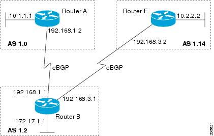
Router A
router bgp 65536
 bgp router-id 10.1.1.99
 no bgp default ipv4-unicast
 bgp fast-external-fallover
 bgp log-neighbor-changes
 timers bgp 70 120
 neighbor 192.168.1.1 remote-as 65538
 !
 address-family ipv4
  neighbor 192.168.1.1 activate
  no auto-summary
  no synchronization
  network 10.1.1.0 mask 255.255.255.0
  exit-address-family
Router B
router bgp 65538
 bgp router-id 172.17.1.99
 no bgp default ipv4-unicast
 bgp fast-external-fallover
 bgp log-neighbor-changes
 timers bgp 70 120
 neighbor 192.168.1.2 remote-as 65536
 neighbor 192.168.3.2 remote-as 65550
 neighbor 192.168.3.2 description finance
 !
 address-family ipv4
  neighbor 192.168.1.2 activate
  neighbor 192.168.3.2 activate
  no auto-summary
  no synchronization
  network 172.17.1.0 mask 255.255.255.0
  exit-address-family
Router E
router bgp 65550
 bgp router-id 10.2.2.99
 no bgp default ipv4-unicast
 bgp fast-external-fallover
 bgp log-neighbor-changes
 timers bgp 70 120
 neighbor 192.168.3.1 remote-as 65538
 !
 address-family ipv4
  neighbor 192.168.3.1 activate
  no auto-summary
  no synchronization
  network 10.2.2.0 mask 255.255.255.0
  exit-address-family
Asdot Default Format in Cisco IOS Release 12.0(32)S12, and 12.4(24)T
The following example is available in Cisco IOS Release 12.0(32)S12, and 12.4(24)T and shows how to create the configuration for Router A, Router B, and Router E in the figure below with a BGP process configured between three neighbor peers (at Router A, at Router B, and at Router E) in separate 4-byte autonomous systems configured using the default asdot format. IPv4 unicast routes are exchanged with all peers.
| Figure 7 | BGP Peers Using 4-Byte Autonomous System Numbers in Asdot Format |
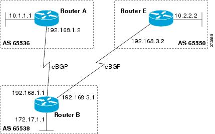
Router A
router bgp 1.0
 bgp router-id 10.1.1.99
 no bgp default ipv4-unicast
 bgp fast-external-fallover
 bgp log-neighbor-changes
 timers bgp 70 120
 neighbor 192.168.1.1 remote-as 1.2
 !
 address-family ipv4
  neighbor 192.168.1.1 activate
  no auto-summary
  no synchronization
  network 10.1.1.0 mask 255.255.255.0
  exit-address-family
Router B
router bgp 1.2
 bgp router-id 172.17.1.99
 no bgp default ipv4-unicast
 bgp fast-external-fallover
 bgp log-neighbor-changes
 timers bgp 70 120
 neighbor 192.168.1.2 remote-as 1.0
 neighbor 192.168.3.2 remote-as 1.14
 neighbor 192.168.3.2 description finance
 !
 address-family ipv4
  neighbor 192.168.1.2 activate
  neighbor 192.168.3.2 activate
  no auto-summary
  no synchronization
  network 172.17.1.0 mask 255.255.255.0
  exit-address-family
Router E
router bgp 1.14
 bgp router-id 10.2.2.99
 no bgp default ipv4-unicast
 bgp fast-external-fallover
 bgp log-neighbor-changes
 timers bgp 70 120
 neighbor 192.168.3.1 remote-as 1.2
 !
 address-family ipv4
  neighbor 192.168.3.1 activate
  no auto-summary
  no synchronization
  network 10.2.2.0 mask 255.255.255.0
  exit-address-family
Examples Configuring a VRF and Setting an Extended Community Using a BGP 4-Byte Autonomous System Number
Asplain Default Format in Cisco IOS Release 12.0(32)SY8, 12.0(33)S3, 12.2(33)SRE, 12.2(33)SXI1, and Later Releases
The following example is available in Cisco IOS Release 12.0(32)SY8, 12.0(33)S3, 12.2(33)SRE, 12.2(33)XNE, 12.2(33)SXI1, and later releases and shows how to create a VRF with a route-target that uses a 4-byte autonomous system number, 65537, and how to set the route target to extended community value 65537:100 for routes that are permitted by the route map.
ip vrf vpn_red
 rd 64500:100
 route-target both 65537:100
 exit
route-map red_map permit 10
 set extcommunity rt 65537:100
 end
After the configuration is completed, use the show route-map command to verify that the extended community is set to the route target that contains the 4-byte autonomous system number of 65537.
RouterB# show route-map red_map
route-map red_map, permit, sequence 10
  Match clauses:
  Set clauses:
    extended community RT:65537:100
  Policy routing matches: 0 packets, 0 bytes
Asdot Default Format in Cisco IOS Release 12.0(32)S12, and 12.4(24)T
The following example is available in Cisco IOS Release 12.0(32)S12, and 12.4(24)T and shows how to create a VRF with a route-target that uses a 4-byte autonomous system number, 1.1, and how to set the route target to extended community value 1.1:100 for routes that are permitted by the route map.
Note |
In Cisco IOS Release 12.0(32)SY8, 12.0(33)S3, 12.2(33)SXI1, and later releases, this example works if you have configured asdot as the default display format using the bgp asnotation dot command. |
ip vrf vpn_red
 rd 64500:100
 route-target both 1.1:100
 exit
route-map red_map permit 10
 set extcommunity rt 1.1:100
 end
After the configuration is completed, use the show route-map command to verify that the extended community is set to the route target that contains the 4-byte autonomous system number of 1.1.
RouterB# show route-map red_map
route-map red_map, permit, sequence 10
  Match clauses:
  Set clauses:
    extended community RT:1.1:100
  Policy routing matches: 0 packets, 0 bytes
Example NLRI to AFI Configuration
The following example upgrades an existing router configuration file in the NLRI format to the AFI format and set the router CLI to use only commands in the AFI format:
router bgp 60000
 bgp upgrade-cli
The show running-config command can be used in privileged EXEC mode to verify that an existing router configuration file has been upgraded from the NLRI format to the AFI format. The following sections provide sample output from a router configuration file in the NLRI format, and the same router configuration file after it has been upgraded to the AFI format with the bgp upgrade-cli command in router configuration mode.
Note |
After a router has been upgraded from the AFI format to the NLRI format with the bgp upgrade-clicommand, NLRI commands will no longer be accessible or configurable. |
Router Configuration File in NLRI Format Before Upgrading
The following sample output is from the show running-config command in privileged EXEC mode. The sample output shows a router configuration file, in the NLRI format, prior to upgrading to the AFI format with the bgp upgrade-cli command. The sample output is filtered to show only the affected portion of the router configuration.
Router# show running-config | begin bgp
router bgp 101
 no synchronization
 bgp log-neighbor-changes
 neighbor 10.1.1.1 remote-as 505 nlri unicast multicast
 no auto-summary
!
ip default-gateway 10.4.9.1
ip classless
!
!
route-map REDISTRIBUTE-MULTICAST permit 10
 match ip address prefix-list MULTICAST-PREFIXES
 set nlri multicast
!
route-map MULTICAST-PREFIXES permit 10
!
route-map REDISTRIBUTE-UNICAST permit 20
 match ip address prefix-list UNICAST-PREFIXES
 set nlri unicast
!
!
!
line con 0
line aux 0
line vty 0 4
 password PASSWORD
 login
!
end
Router Configuration File in AFI Format After Upgrading
The following sample output shows the router configuration file after it has been upgraded to the AFI format. The sample output is filtered to show only the affected portion of the router configuration file.
Router# show running-config | begin bgp
router bgp 101
 bgp log-neighbor-changes
 neighbor 10.1.1.1 remote-as 505
 no auto-summary
 !
 address-family ipv4 multicast
  neighbor 10.1.1.1 activate
  no auto-summary
  no synchronization
  exit-address-family
 !
 address-family ipv4
  neighbor 10.1.1.1 activate
  no auto-summary
  no synchronization
  exit-address-family
!
ip default-gateway 10.4.9.1
ip classless
!
!
route-map REDISTRIBUTE-MULTICAST_mcast permit 10
 match ip address prefix-list MULTICAST-PREFIXES
!
route-map REDISTRIBUTE-MULTICAST permit 10
 match ip address prefix-list MULTICAST-PREFIXES
!
route-map MULTICAST-PREFIXES permit 10
!
route-map REDISTRIBUTE-UNICAST permit 20
 match ip address prefix-list UNICAST-PREFIXES
!
!
!
line con 0
line aux 0
line vty 0 4
 password PASSWORD
 login
!
end
Examples Removing BGP Configuration Commands Using a Redistribution Example
The following examples show both the CLI configuration to enable the redistribution of BGP routes into EIGRP using a route map, and the CLI configuration to remove the redistribution and route map. Some BGP configuration commands can affect other CLI commands and this example demonstrates how the removal of one command affects another command.
In the first configuration example, a route map is configured to match and set autonomous system numbers. BGP neighbors in three different autonomous systems are configured and activated. An EIGRP routing process is started, and the redistribution of BGP routes into EIGRP using the route map is configured.
CLI to Enable BGP Route Redistribution Into EIGRP
route-map bgp-to-eigrp permit 10
 match tag 50000
 set tag 65000
 exit
router bgp 45000
 bgp log-neighbor-changes
 address-family ipv4
  neighbor 172.16.1.2 remote-as 45000
  neighbor 172.21.1.2 remote-as 45000
  neighbor 192.168.1.2 remote-as 40000
  neighbor 192.168.3.2 remote-as 50000
  neighbor 172.16.1.2 activate
  neighbor 172.21.1.2 activate
  neighbor 192.168.1.2 activate
  neighbor 192.168.3.2 activate
  network 172.17.1.0 mask 255.255.255.0
  exit-address-family
 exit
router eigrp 100
 redistribute bgp 45000 metric 10000 100 255 1 1500 route-map bgp-to-eigrp
 no auto-summary
 exit
In the second configuration example, both the route-map command and the redistribute command are disabled. If only the route-map command is removed, it does not automatically disable the redistribution. The redistribution will now occur without any matching or filtering. To remove the redistribution configuration, the redistribute command must also be disabled.
CLI to Remove BGP Route Redistribution Into EIGRP
configure terminal
 no route-map bgp-to-eigrp
 router eigrp 100
  no redistribute bgp 45000
  end
Examples BGP Soft Reset
The following examples show two ways to reset the connection for BGP peer 192.168.1.1.
Dynamic Inbound Soft Reset Example
The following example shows the clear ip bgp 192.168.1.1 soft in EXEC command used to initiate a dynamic soft reconfiguration in the BGP peer 192.168.1.1. This command requires that the peer support the route refresh capability.
clear ip bgp 192.168.1.1 soft in
Inbound Soft Reset Using Stored Information Example
The following example shows how to enable inbound soft reconfiguration for the neighbor 192.168.1.1. All the updates received from this neighbor will be stored unmodified, regardless of the inbound policy. When inbound soft reconfiguration is performed later, the stored information will be used to generate a new set of inbound updates.
router bgp 100
 neighbor 192.168.1.1 remote-as 200
 neighbor 192.168.1.1 soft-reconfiguration inbound
The following example clears the session with the neighbor 192.168.1.1:
clear ip bgp 192.168.1.1 soft in
Example Resetting BGP Peers Using 4-Byte Autonomous System Numbers
The following examples show how to clear BGP peers belonging to an autonomous system that uses 4-byte autonomous system numbers. This example requires Cisco IOS Release 12.0(32)SY8, 12.0(33)S3, 12.2(33)SRE, 12.2(33)XNE, 12.2(33)SXI1, or a later release to be running on the router. The initial state of the BGP routing table is shown using the show ip bgp command, and peers in 4-byte autonomous systems 65536 and 65550 are displayed.
RouterB# show ip bgp

BGP table version is 4, local router ID is 172.17.1.99
Status codes: s suppressed, d damped, h history, * valid, > best, i - internal,
              r RIB-failure, S Stale
Origin codes: i - IGP, e - EGP, ? - incomplete
   Network          Next Hop            Metric LocPrf Weight Path
*> 10.1.1.0/24      192.168.1.2              0             0 65536  i
*> 10.2.2.0/24      192.168.3.2              0             0 65550  i
*> 172.17.1.0/24    0.0.0.0                  0         32768 i
The clear ip bgp 65550 command is entered to remove all BGP peers in the 4-byte autonomous system 65550. The ADJCHANGE message shows that the BGP peer at 192.168.3.2 is being reset.
RouterB# clear ip bgp 65550
RouterB#
*Nov 30 23:25:27.043: %BGP-5-ADJCHANGE: neighbor 192.168.3.2 Down User reset
The show ip bgp command is entered again, and only the peer in 4-byte autonomous systems 65536 is now displayed.
RouterB# show ip bgp
BGP table version is 5, local router ID is 172.17.1.99
Status codes: s suppressed, d damped, h history, * valid, > best, i - internal,
              r RIB-failure, S Stale
Origin codes: i - IGP, e - EGP, ? - incomplete
   Network          Next Hop            Metric LocPrf Weight Path
*> 10.1.1.0/24      192.168.1.2              0             0 65536  i
*> 172.17.1.0/24    0.0.0.0                  0         32768 i
Almost immediately the next ADJCHANGE message shows that the BGP peer at 192.168.3.2 (in the 4-byte autonomous system 65550) is now back up.
RouterB#
*Nov 30 23:25:55.995: %BGP-5-ADJCHANGE: neighbor 192.168.3.2 Up
Example Resetting and Displaying Basic BGP Information
The following example shows how to reset and display basic BGP information.
The clear ip bgp * command clears and resets all the BGP neighbor sessions. In Cisco IOS Release 12.2(25)S and later releases, the syntax is clear ip bgp all. Specific neighbors or all peers in an autonomous system can be cleared by using the neighbor-address and autonomous-system-number arguments. If no argument is specified, this command will clear and reset all BGP neighbor sessions.
Note |
The clear ip bgp * command also clears all the internal BGP structures which makes it useful as a troubleshooting tool. |
Router# clear ip bgp *
The show ip bgp command is used to display all the entries in the BGP routing table. The following example displays BGP routing table information for the 10.1.1.0 network:
Router# show ip bgp 10.1.1.0 255.255.255.0
BGP routing table entry for 10.1.1.0/24, version 2
Paths: (1 available, best #1, table Default-IP-Routing-Table)
  Advertised to update-groups:
     1
  40000
    192.168.1.2 from 192.168.1.2 (10.1.1.99)
      Origin IGP, metric 0, localpref 100, valid, external, best
The show ip bgp neighborscommand is used to display information about the TCP and BGP connections to neighbors. The following example displays the routes that were advertised from Router B in the figure above (in the "Configuring a BGP Peer for the IPv4 VRF Address Family" section) to its BGP neighbor 192.168.3.2 on Router E:
Router# show ip bgp neighbors 192.168.3.2 advertised-routes
BGP table version is 3, local router ID is 172.17.1.99
Status codes: s suppressed, d damped, h history, * valid, > best, i - internal,
              r RIB-failure, S Stale
Origin codes: i - IGP, e - EGP, ? - incomplete
   Network          Next Hop            Metric LocPrf Weight Path
*> 10.1.1.0/24      192.168.1.2              0             0 40000 i
*> 172.17.1.0/24    0.0.0.0                  0         32768 i
Total number of prefixes 2
The show ip bgp pathscommand is used to display all the BGP paths in the database. The following example displays BGP path information for Router B in the figure above (in the "Customizing a BGP Peer" section):
Router# show ip bgp paths
Address    Hash Refcount Metric Path
0x2FB5DB0     0        5      0 i
0x2FB5C90     1        4      0 i
0x2FB5C00  1361        2      0 50000 i
0x2FB5D20  2625        2      0 40000 i
The show ip bgp summarycommand is used to display the status of all BGP connections. The following example displays BGP routing table information for Router B in the figure above (in the "Customizing a BGP Peer" section:
Router# show ip bgp summary
BGP router identifier 172.17.1.99, local AS number 45000
BGP table version is 3, main routing table version 3
2 network entries using 234 bytes of memory
2 path entries using 104 bytes of memory
4/2 BGP path/bestpath attribute entries using 496 bytes of memory
2 BGP AS-PATH entries using 48 bytes of memory
0 BGP route-map cache entries using 0 bytes of memory
0 BGP filter-list cache entries using 0 bytes of memory
BGP using 882 total bytes of memory
BGP activity 14/10 prefixes, 16/12 paths, scan interval 60 secs
Neighbor        V    AS MsgRcvd MsgSent   TblVer  InQ OutQ Up/Down  State/PfxRcd
192.168.1.2     4 40000     667     672        3    0    0 00:03:49        1
192.168.3.2     4 50000     468     467        0    0    0 00:03:49 (NoNeg)
Examples Aggregating Prefixes Using BGP
The following examples show how you can use aggregate routes in BGP either by redistributing an aggregate route into BGP or by using the BGP conditional aggregation routing feature.
In the following example, the redistribute staticrouter configuration command is used to redistribute aggregate route 10.0.0.0:
ip route 10.0.0.0 255.0.0.0 null 0
!
router bgp 100
 redistribute static
The following configuration shows how to create an aggregate entry in the BGP routing table when at least one specific route falls into the specified range. The aggregate route will be advertised as coming from your autonomous system and has the atomic aggregate attribute set to show that information might be missing. (By default, atomic aggregate is set unless you use the as-set keyword in the aggregate-addressrouter configuration command.)
router bgp 100
 aggregate-address 10.0.0.0 255.0.0.0
The following example shows how to create an aggregate entry using the same rules as in the previous example, but the path advertised for this route will be an AS-SET consisting of all elements contained in all paths that are being summarized:
router bgp 100
 aggregate-address 10.0.0.0 255.0.0.0 as-set
The following example shows how to create the aggregate route for 10.0.0.0 and also suppress advertisements of more specific routes to all neighbors:
router bgp 100
 aggregate-address 10.0.0.0 255.0.0.0 summary-only
The following example, starting in global configuration mode, configures BGP to not advertise inactive routes:
Router(config)# router bgp 50000
Router(config-router)# address-family ipv4 unicast
Router(config-router-af)# bgp suppress-inactive

Router(config-router-af)# end
The following example configures a maximum route limit in the VRF named red and configures BGP to not advertise inactive routes through the VRF named RED:
Router(config)# ip vrf RED

Router(config-vrf)# rd 50000:10
Router(config-vrf)# maximum routes 1000 10

Router(config-vrf)# exit
Router(config)# router bgp 50000
Router(config-router)# address-family ipv4 vrf RED
Router(config-router-af)# bgp suppress-inactive

Router(config-router-af)# end
Example Configuring a BGP Peer Group
The following example shows how to use an address family to configure a peer group so that all members of the peer group are both unicast- and multicast-capable:
router bgp 45000
neighbor 192.168.1.2 remote-as 40000
neighbor 192.168.3.2 remote-as 50000
address-family ipv4 unicast
 neighbor mygroup peer-group
 neighbor 192.168.1.2 peer-group mygroup
 neighbor 192.168.3.2 peer-group mygroup
router bgp 45000
neighbor 192.168.1.2 remote-as 40000
neighbor 192.168.3.2 remote-as 50000
address-family ipv4 multicast
 neighbor mygroup peer-group
 neighbor 192.168.1.2 peer-group mygroup
 neighbor 192.168.3.2 peer-group mygroup
 neighbor 192.168.1.2 activate
 neighbor 192.168.3.2 activate
Example Configuring Peer Session Templates
The following example creates a peer session template named INTERNAL-BGP in session-template configuration mode:
router bgp 45000
 template peer-session INTERNAL-BGP
 remote-as 50000
 timers 30 300
 exit-peer-session
The following example creates a peer session template named CORE1. This example inherits the configuration of the peer session template named INTERNAL-BGP.
router bgp 45000
 template peer-session CORE1
 description CORE-123
 update-source loopback 1
 inherit peer-session INTERNAL-BGP
 exit-peer-session
The following example configures the 192.168.3.2 neighbor to inherit the CORE1 peer session template. The 192.168.3.2 neighbor will also indirectly inherit the configuration from the peer session template named INTERNAL-BGP. The explicit remote-as statement is required for the neighbor inherit statement to work. If a peering is not configured, the specified neighbor will not accept the session template.
router bgp 45000
 neighbor 192.168.3.2 remote-as 50000
 neighbor 192.168.3.2 inherit peer-session CORE1
Example Configuring Peer Policy Templates
The following example creates a peer policy template named GLOBAL in policy-template configuration mode:
router bgp 45000
 template peer-policy GLOBAL
 weight 1000
 maximum-prefix 5000
 prefix-list NO_SALES in
 exit-peer-policy
The following example creates a peer policy template named PRIMARY-IN in policy-template configuration mode:
template peer-policy PRIMARY-IN
 prefix-list ALLOW-PRIMARY-A in
 route-map SET-LOCAL in
 weight 2345
 default-originate
 exit-peer-policy
The following example creates a peer policy template named CUSTOMER-A. This peer policy template is configured to inherit the configuration from the peer policy templates named PRIMARY-IN and GLOBAL.
template peer-policy CUSTOMER-A
 route-map SET-COMMUNITY in
 filter-list 20 in
 inherit peer-policy PRIMARY-IN 20
 inherit peer-policy GLOBAL 10
 exit-peer-policy
The following example configures the 192.168.2.2 neighbor in address family mode to inherit the peer policy template name CUSTOMER-A. The 192.168.2.2 neighbor will also indirectly inherit the peer policy templates named PRIMARY-IN and GLOBAL.
router bgp 45000
 neighbor 192.168.2.2 remote-as 50000
 address-family ipv4 unicast
  neighbor 192.168.2.2 inherit peer-policy CUSTOMER-A
  end
Examples Monitoring and Maintaining BGP Dynamic Update Peer-Groups
No configuration is required to enable the BGP dynamic update of peer groups and the algorithm runs automatically. The following examples show how BGP update group information can be cleared or displayed.
clear ip bgp update-group Example
The following example clears the membership of neighbor 10.0.0.1 from an update group:
Router#
 clear ip bgp update-group 10.0.0.1
debug ip bgp groups Example
The following example output from the debug ip bgp groups command shows the recalculation of update groups after the clear ip bgp groups command was issued:
Router# debug ip bgp groups
5w4d: %BGP-5-ADJCHANGE: neighbor 10.4.9.5 Down User reset
5w4d: BGP-DYN(0): Comparing neighbor 10.4.9.5 flags 0x0 cap 0x0 and updgrp 2 fl0
5w4d: BGP-DYN(0): Update-group 2 flags 0x0 cap 0x0 policies same as 10.4.9.5 fl0
5w4d: %BGP-5-ADJCHANGE: neighbor 10.4.9.8 Down User reset
5w4d: BGP-DYN(0): Comparing neighbor 10.4.9.8 flags 0x0 cap 0x0 and updgrp 2 fl0
5w4d: BGP-DYN(0): Update-group 2 flags 0x0 cap 0x0 policies same as 10.4.9.8 fl0
5w4d: %BGP-5-ADJCHANGE: neighbor 10.4.9.21 Down User reset
5w4d: BGP-DYN(0): Comparing neighbor 10.4.9.21 flags 0x0 cap 0x0 and updgrp 1 f0
5w4d: BGP-DYN(0): Update-group 1 flags 0x0 cap 0x0 policies same as 10.4.9.21 f0
5w4d: %BGP-5-ADJCHANGE: neighbor 10.4.9.5 Up
5w4d: %BGP-5-ADJCHANGE: neighbor 10.4.9.21 Up
5w4d: %BGP-5-ADJCHANGE: neighbor 10.4.9.8 Up
show ip bgp replication Example
The following sample output from the show ip bgp replicationcommand shows update group replication information for all for neighbors:
Router# show ip bgp replication
BGP Total Messages Formatted/Enqueued : 0/0
     Index     Type  Members          Leader   MsgFmt  MsgRepl  Csize  Qsize
         1 internal        1       10.4.9.21        0        0      0      0
         2 internal        2        10.4.9.5        0        0      0      0
show ip bgp update-group Example
The following sample output from the show ip bgp update-group command shows update group information for all neighbors:
Router# show ip bgp update-group
BGP version 4 update-group 1, internal, Address Family: IPv4 Unicast
  BGP Update version : 0, messages 0/0
  Route map for outgoing advertisements is COST1
  Update messages formatted 0, replicated 0
  Number of NLRIs in the update sent: max 0, min 0
  Minimum time between advertisement runs is 5 seconds
  Has 1 member:
  10.4.9.21
BGP version 4 update-group 2, internal, Address Family: IPv4 Unicast
  BGP Update version : 0, messages 0/0
  Update messages formatted 0, replicated 0
  Number of NLRIs in the update sent: max 0, min 0
  Minimum time between advertisement runs is 5 seconds
  Has 2 members:
  10.4.9.5 10.4.9.8
Where to Go Next
- If you want to connect to an external service provider, see the "Connecting to a Service Provider Using External BGP" module.
- To configure BGP neighbor session options, proceed to the "Configuring BGP Neighbor Session Options" module.
- If you want to configure some iBGP features, see the "Configuring Internal BGP Features" module.
Additional References
Related Documents
| Related Topic |
Document Title |
|---|---|
| Cisco IOS commands |
Cisco IOS Master Commands List, All Releases |
| BGP commands: complete command syntax, command mode, defaults, command history, usage guidelines, and examples |
Cisco IOS IP Routing: BGP Command Reference |
| IPv6 commands: complete command syntax, command mode, defaults, usage guidelines, and examples |
Cisco IOS IPv6 Command Reference |
| Overview of Cisco BGP conceptual information with links to all the individual BGP modules |
"Cisco BGP Overview" module |
| Multiprotocol Label Switching (MPLS) and BGP configuration example using the IPv4 VRF address family |
"Providing VPN Connectivity Across Multiple Autonomous Systems with MPLS VPN Inter-AS with ASBRs Exchanging IPv4 Routes and MPLS Labels" module |
| Basic MPLS VPN and BGP configuration example |
"Configuring MPLS Layer 3 VPNs" module |
Standards
| Standard |
Title |
|---|---|
| MDT SAFI |
MIBs
| MIB |
MIBs Link |
|---|---|
| CISCO-BGP4-MIB |
To locate and download MIBs for selected platforms, Cisco IOS releases, and feature sets, use Cisco MIB Locator found at the following URL: |
RFCs
| RFC |
Title |
|---|---|
| RFC 1772 |
Application of the Border Gateway Protocol in the Internet |
| RFC 1773 |
Experience with the BGP Protocol |
| RFC 1774 |
BGP-4 Protocol Analysis |
| RFC 1930 |
Guidelines for Creation, Selection, and Registration of an Autonomous System (AS) |
| RFC 2519 |
A Framework for Inter-Domain Route Aggregation |
| RFC 2858 |
Multiprotocol Extensions for BGP-4 |
| RFC 2918 |
Route Refresh Capability for BGP-4 |
| RFC 3392 |
Capabilities Advertisement with BGP-4 |
| RFC 4271 |
A Border Gateway Protocol 4 (BGP-4) |
| RFC 4893 |
BGP Support for Four-octet AS Number Space |
| RFC 5396 |
Textual Representation of Autonomous system (AS) Numbers |
| RFC 5398 |
Autonomous System (AS) Number Reservation for Documentation Use |
Technical Assistance
| Description |
Link |
|---|---|
| The Cisco Support and Documentation website provides online resources to download documentation, software, and tools. Use these resources to install and configure the software and to troubleshoot and resolve technical issues with Cisco products and technologies. Access to most tools on the Cisco Support and Documentation website requires a Cisco.com user ID and password. |
Feature Information for Configuring a Basic BGP Network
The following table provides release information about the feature or features described in this module. This table lists only the software release that introduced support for a given feature in a given software release train. Unless noted otherwise, subsequent releases of that software release train also support that feature.
Use Cisco Feature Navigator to find information about platform support and Cisco software image support. To access Cisco Feature Navigator, go to www.cisco.com/go/cfn. An account on Cisco.com is not required.
| Table 6 | Feature Information for Configuring a Basic BGP Network |
| Feature Name |
Releases |
Feature Configuration Information |
|---|---|---|
| BGP Version 4 |
Cisco IOS XE 3.1.0SG |
BGP is an interdomain routing protocol designed to provide loop-free routing between separate routing domains that contain independent routing policies (autonomous systems). The Cisco IOS software implementation of BGP version 4 includes multiprotocol extensions to allow BGP to carry routing information for IP multicast routes and multiple Layer 3 protocol address families including IP Version 4 (IPv4), IP Version 6 (IPv6), Virtual Private Networks version 4 (VPNv4), and Connectionless Network Services (CLNS). |
| BGP Conditional Route Injection |
12.0(22)S 12.2(4)T 12.2(14)S 15.0(1)S Cisco IOS XE 3.1.0SG |
The BGP Conditional Route Injection feature allows you to inject more specific prefixes into a BGP routing table over less specific prefixes that were selected through normal route aggregation. These more specific prefixes can be used to provide a finer granularity of traffic engineering or administrative control than is possible with aggregated routes. |
| BGP Configuration Using Peer Templates |
12.0(24)S 12.2(18)S 12.2(27)SBC 12.3(4)T 15.0(1)S |
The BGP Configuration Using Peer Templates feature introduces a new mechanism that groups distinct neighbor configurations for BGP neighbors that share policies. This type of policy configuration has been traditionally configured with BGP peer groups. However, peer groups have certain limitations because peer group configuration is bound to update grouping and specific session characteristics. Configuration templates provide an alternative to peer group configuration and overcome some of the limitations of peer groups. |
| BGP Dynamic Update Peer Groups |
12.0(24)S 12.2(18)S 12.2(27)SBC 12.3(4)T 15.0(1)S Cisco IOS XE 3.1.0SG |
The BGP Dynamic Update Peer Groups feature introduces a new algorithm that dynamically calculates and optimizes update groups of neighbors that share the same outbound policies and can share the same update messages. In previous versions of Cisco IOS software, BGP update messages were grouped based on peer-group configurations. This method of grouping updates limited outbound policies and specific-session configurations. The BGP Dynamic Update Peer Group feature separates update group replication from peer group configuration, which improves convergence time and flexibility of neighbor configuration. |
| BGP Hybrid CLI |
12.0(22)S 12.2(15)T 15.0(1)S |
The BGP Hybrid CLI feature simplifies the migration of BGP networks and existing configurations from the NLRI format to the AFI format. This new functionality allows the network operator to configure commands in the AFI format and save these command configurations to existing NLRI formatted configurations. The feature provides the network operator with the capability to take advantage of new features and provides support for migration from the NLRI format to the AFI format. |
| BGP Neighbor Policy |
12.2(33)SB 12.2(33)SRB 12.4(11)T Cisco IOS XE 3.1.0SG |
The BGP Neighbor Policy feature introduces new keywords to two existing commands to display information about local and inherited policies. When BGP neighbors use multiple levels of peer templates, it can be difficult to determine which policies are applied to the neighbor. Inherited policies are policies that the neighbor inherits from a peer-group or a peer-policy template. The following commands were modified by this feature: show ip bgp neighbors, show ip bgp template peer-policy. |
| BGP Support for 4-Byte ASN |
12.0(32)S12 12.0(32)SY8 12.0(33)S3 12.2(33)SRE 12.2(33)XNE 12.2(33)SXI1, 12.4(24)T 15.0(1)S Cisco IOS XE 3.1.0SG |
The BGP Support for 4-Byte ASN feature introduced support for 4-byte autonomous system numbers. Because of increased demand for autonomous system numbers, in January 2009 the IANA will start to allocate 4-byte autonomous system numbers in the range from 65536 to 4294967295. In Cisco IOS Release 12.0(32)SY8, 12.0(33)S3, 12.2(33)SRE, 12.2(33)XNE, 12.2(33)SXI1, and later releases, the Cisco implementation of 4-byte autonomous system numbers uses asplain as the default regular expression match and output display format for autonomous system numbers, but you can configure 4-byte autonomous system numbers in both the asplain format and the asdot format as described in RFC 5396. To change the default regular expression match and output display of 4-byte autonomous system numbers to asdot format, use the bgp asnotation dot command. In Cisco IOS Release 12.0(32)S12, and 12.4(24)T, the Cisco implementation of 4-byte autonomous system numbers uses asdot as the only configuration format, regular expression match, and output display, with no asplain support. The following commands were introduced or modified by this feature: bgp asnotation dot, bgp confederation identifier, bgp confederation peers, all clear ip bgpcommands that configure an autonomous system number, ip as-path access-list, ip extcommunity-list, match source-protocol, neighbor local-as, neighbor remote-as, neighbor soo, redistribute (IP), router bgp, route-target, set as-path, set extcommunity, set origin, soo, all show ip bgp commands that display an autonomous system number, and show ip extcommunity-list. |
| Suppress BGP Advertisement for Inactive Routes |
12.2(25)S 12.2(33)SXH 15.0(1)M 15.0(1)S |
The Suppress BGP Advertisements for Inactive Routes feature allows you to configure the suppression of advertisements for routes that are not installed in the Routing Information Base (RIB). Configuring this feature allows Border Gateway Protocol (BGP) updates to be more consistent with data used for traffic forwarding. |
Cisco and the Cisco Logo are trademarks of Cisco Systems, Inc. and/or its affiliates in the U.S. and other countries. A listing of Cisco's trademarks can be found at www.cisco.com/go/trademarks. Third party trademarks mentioned are the property of their respective owners. The use of the word partner does not imply a partnership relationship between Cisco and any other company. (1005R)
Any Internet Protocol (IP) addresses and phone numbers used in this document are not intended to be actual addresses and phone numbers. Any examples, command display output, network topology diagrams, and other figures included in the document are shown for illustrative purposes only. Any use of actual IP addresses or phone numbers in illustrative content is unintentional and coincidental.
 Feedback