- Integrated IS-IS Routing Protocol Overview
- Configuring a Basic IS-IS Network
- Customizing IS-IS for Your Network Design
- IS-IS MIB
- IS-IS Support for an IS-IS Instance per VRF for IP
- Overview of IS-IS Fast Convergence
- Setting Best Practice Parameters for IS-IS Fast Convergence
- Reducing Failure Detection Times in IS-IS Networks
- Reducing Link Failure and Topology Change Notification Times in IS-IS Networks
- Reducing Alternate-Path Calculation Times in IS-IS Networks
- Enhancing Security in an IS-IS Network
- Finding Feature Information
- Prerequisites for the Integrated IS-IS Routing Protocol
- Information About the Integrated IS-IS Routing Protocol
- Where to Go Next
- Additional References
- Glossary
Integrated IS-IS Routing Protocol Overview
This module provides a technical overview of the Integrated Intermediate System-to-Intermediate System (IS-IS) routing protocol. IS-IS is a link-state Interior Gateway Protocol (IGP). Link-state protocols are characterized by the propagation of the information required to build a complete network connectivity map on each participating router. That map is then used to calculate the shortest path to destinations.
The IS-IS protocol was developed in the late 1980s by Digital Equipment Corporation (DEC) and was standardized by the International Standards Organization (ISO) in ISO/IEC 10589. The current version of this standard is ISO/IEC 10589:2002.
ISO/IEC 10589 defines support for the ISO Connectionless Network Protocol (CLNP) as defined in ISO 8473. However, the protocol was designed to be extensible to other network protocols. RFC 1195 defined IS-IS support for IP, and additional IETF extensions have defined IS-IS support for IPv6. Integration of support for multiple network layer protocols has led to the term Integrated IS-IS. The Cisco IOS IS-IS implementation supports CLNP, IPv4, and IPv6. This module and its related modules use the term IS-IS to refer to the Integrated IS-IS that is implemented by Cisco IOS software.
Finding Feature Information
Your software release may not support all the features documented in this module. For the latest feature information and caveats, see the release notes for your platform and software release. To find information about the features documented in this module, and to see a list of the releases in which each feature is supported, see the Feature Information Table at the end of this document.
Use Cisco Feature Navigator to find information about platform support and Cisco software image support. To access Cisco Feature Navigator, go to www.cisco.com/go/cfn. An account on Cisco.com is not required.
Prerequisites for the Integrated IS-IS Routing Protocol
This document assumes knowledge of CLNS, IPv4, and IPv6. The amount of knowledge required for each technology is dependent on your deployment.
Information About the Integrated IS-IS Routing Protocol
- IS-IS Functional Overview
- IS Address Assignment
- IS-IS PDU Types
- IS-IS Supported Circuit Types
- IS-IS Election of the Designated Intermediate System
- IS-IS Overview of LSPDB Synchronization
- IS-IS Overview of the Shortest Path Calculation
IS-IS Functional Overview
A routing domain may be divided into one or more subdomains. Each subdomain is referred to as an area and is assigned an area address. Routing within an area is referred to as Level-1 routing. Routing between Level-1 areas is referred to as Level-2 routing. A router in OSI terminology is referred to as an Intermediate System (IS). An IS may operate at Level 1, Level 2, or both. ISs that operate at Level 1 exchange routing information with other Level-1 ISs in the same area. ISs that operate at Level 2 exchange routing information with other Level-2 routers regardless of whether they are in the same Level-1 area. The set of Level-2 routers and the links that interconnect them form the Level-2 subdomain, which must not be partitioned in order for routing to work properly.
IS Address Assignment
An IS is identified by an address known as a Network Entity Title (NET). The NET is the address of a Network Service Access Point (NSAP), which identifies an instance of the IS-IS routing protocol running on an IS. The NET may be 8 to 20 octets in length and consists of three parts:
- Area address--This field is 1 to 13 octets in length and is composed of high-order octets of the address.
 Note |
An IS-IS instance may be assigned multiple area addresses. When this is the case, all area addresses are considered synonymous. Multiple synonymous area addresses are useful when merging or splitting areas in the domain. In normal operation, for example, once the merge or split has been completed, there is no need to assign more than one area address to an IS-IS instance. |
- System ID--This field is 6 octets long and immediately follows the area address. When the IS operates at Level 1, the system ID must be unique among all the Level-1 routers in the same area. When the IS operates at Level 2, the system ID must be unique among all routers in the domain.
Note |
An IS instance is assigned exactly one system ID. |
- NSEL--The N-selector field is 1 octet in length and immediately follows the system ID. It must be set to "00".
The figure below shows the format for the NET.
| Figure 1 | NET Format |

IS-IS PDU Types
ISs exchange routing information with their peers using protocol data units (PDUs). The following types of PDUs are used:
IIHs
Intermediate System-to-Intermediate System Hello PDUs (IIHs) are exchanged between IS neighbors on circuits on which the IS-IS protocol is enabled. IIHs include the system ID of the sender, the assigned area address(es), and the identity of neighbors on that circuit that are known to the sending IS. Additional optional information may also be included.
There are three types of IIHs:
- Point-to-Point IIHs--These are sent on point-to-point circuits.
- Level-1 LAN IIHs--These are sent on multiaccess circuits when the sending IS operates as a Level-1 router on that circuit.
- Level-2 LAN IIHs--These are sent on multiaccess circuits when the sending IS operates as a Level-2 router on that circuit.
LSPs
An IS generates Link-State PDUs (LSPs) to advertise its neighbors and the destination that are directly connected to the IS. An LSP is uniquely identified by the following:
- System ID of the IS that generated the LSP
- pseudonode ID--This is always 0 except when the LSP is a pseudonode LSP (see Operation of IS-IS on Multiaccess Circuits)
- LSP number (0 to 255)
- 32-bit sequence number
Whenever a new version of an LSP is generated, the sequence number is incremented.
Level-1 LSPs are generated by ISs that support Level 1. The Level-1 LSPs are flooded throughout the Level-1 area. The set of Level-1 LSPs generated by all Level-1 ISs in an area is the Level-1 LSP Database (LSPDB). All Level-1 ISs in an area will have an identical Level-1 LSPDB and will therefore have an identical network connectivity map for the area.
Level-2 LSPs are generated by ISs that support Level 2. Level-2 LSPs are flooded throughout the Level-2 subdomain. The set of Level-2 LSPs generated by all Level-2 ISs in the domain is the Level-2 LSP Database (LSPDB). All Level-2 ISs will have an identical Level-2 LSPDB and will therefore have an identical connectivity map for the Level-2 subdomain.
SNPs
Sequence Number PDUs (SNPs) contain a summary description of one or more LSPs. There are two types of SNPs--complete and partial--for both Level 1 and Level 2.
- Complete Sequence Number PDUs (CSNPs) are used to send a summary of the LSPDB that an IS has for a given level.
- Partial Sequence Number PDUs (PSNPs) are used to send a summary of a subset of the LSPs for a given level that an IS either has in its database or needs to obtain.
For more information about how SNPs are used, see the IS-IS Supported Circuit Types.
IS-IS Supported Circuit Types
IS-IS supports two generic circuit types:
- Point-to-point circuits
- Multiaccess circuits
Operation of IS-IS on Point-to-Point Circuits
A point-to-point circuit has exactly two ISs on the circuit. An IS forms a single adjacency to the other IS on the point-to-point circuit. The adjacency type describes what level(s) are supported on that circuit.
If both ISs support Level 1 on that circuit and the ISs are configured with at least one matching address, the adjacency supports Level 1. Level-1 LSPs and SNPs will be sent on that circuit.
If both ISs support Level 2 on that circuit, the adjacency supports Level 2. Level-2 LSPs and SNPs will be sent on that circuit.
The adjacency then can be Level 1, Level 2, or Level 1-2.
ISs send point-to-point IIHs on point-to-point circuits. These IIHs allow each IS to discover the identity of the neighbor, the configured area address(es), and the supported levels.
When an adjacency is first established, each IS sends a set of CSNPs for each level that is supported on the circuit. A CSNP set describes the current contents of the LSPDB at that level. By comparing the contents of the set of received CSNPs with the contents of the local LSPDB, each IS can determine where the databases differ and initiate procedures to exchange the necessary LSPs so that the databases are efficiently and reliably synchronized.
PSNPs are sent to acknowledge the receipt of an updated LSP.
Operation of IS-IS on Multiaccess Circuits
Multiaccess circuits support multiple ISs, for example, two or more operating on the circuit. The ability to address multiple systems utilizing a multicast or broadcast address is assumed.
An IS that supports Level 1 on a multiaccess circuit sends Level-1 LAN IIHs on the circuit. An IS that supports Level 2 on a multiaccess circuit sends Level-2 LAN IIHs on the circuit.
ISs form separate adjacencies for each level with neighbor ISs on the circuit.
An IS will form a Level-1 adjacency with other ISs that support Level 1 on the circuit and will have a matching area address. It is a misconfiguration to have two ISs with disjoint sets of area addresses supporting Level 1 on the same multiaccess circuit.
An IS will form a Level-2 adjacency with other ISs that support Level 2 on the circuit.
The routers in the IS-IS network topology in the figure below perform Level 1, Level 2, or Level 1 and 2 routing along the backbone of the network.
| Figure 2 | Level 1, Level 2, and Level 1-2 Routers in an IS-IS Network Topology |

IS-IS Election of the Designated Intermediate System
If each IS advertised all of its adjacencies on a multiaccess circuit in its LSPs, the total number of advertisements required would be N 2 --where N is the number of ISs that operate at a given level on the circuit. To address this scalability issue, IS-IS defines a pseudonode to represent the multiaccess circuit. All ISs that operate on the circuit at a given level elect one of the ISs to act as the Designated Intermediate System (DIS) on that circuit. A DIS is elected for each level that is active on the circuit.
The DIS is responsible for issuing pseudonode LSPs. The pseudonode LSPs include neighbor advertisements for all of the ISs that operate on that circuit. All ISs that operate on the circuit (including the DIS) provide a neighbor advertisement to the pseudonode in their non-pseudonode LSPs and do not advertise any of their neighbors on the multiaccess circuit. In this way the total number of advertisements required varies as a function of N--the number of ISs that operate on the circuit.
A pseudonode LSP is uniquely classified by the following identifiers:
- System ID of the DIS that generated the LSP
- pseudonode ID--ALWAYS NON-ZERO
- LSP number (0 to 255)
- 32-bit sequence number
The nonzero pseudonode ID is what differentiates a pseudonode LSP from a nonpseudonode LSP and is chosen by the DIS to be unique among any other LAN circuits for which it is also the DIS at this level.
The DIS is also responsible for sending periodic CSNPs on the circuit. This provides a complete summary description of the current contents of the LSPDB on the DIS. Other ISs on the circuit can then perform the following activities:
- Flood LSPs that they have that are absent from or are newer than those that are described in the CSNPs sent by the DIS.
- Request an LSP by sending a PSNP for LSPs that are described in the CSNPs sent by the DIS that are absent from the local database or older than what is described in the CSNP set.
In this way, the LSPDBs of all ISs on a multiaccess circuit are efficiently and reliably synchronized.
IS-IS Overview of LSPDB Synchronization
Proper operation of IS-IS requires a reliable and efficient process to synchronize the LSPDBs on each IS. In IS-IS this process is called the update process. This section provides a brief overview of the operation of the update process. The update process operates independently at each supported level.
LSPs may be locally generated, in which case they always are new LSPs. LSPs may also be received from a neighbor on a circuit, in which case they may be generated by some other IS or may be a copy of an LSP generated by the local IS. Received LSPs may be older, the same age, or newer than the current contents of the local LSPDB.
Handling of Newer LSPs
A newer LSP is added to the local LSPDB. If an older copy of the same LSP currently exists in the LSPDB, it is replaced. The newer LSP is marked to be sent on all circuits on which the IS currently has an adjacency in the UP state at the level associated with the newer LSP--excluding the circuit on which the newer LSP was received.
On point-to-point circuits, the newer LSP will be flooded periodically until the neighbor acknowledges its receipt by sending a PSNP or by sending an LSP that is the same or newer than the LSP being flooded.
On multiaccess circuits, the IS will flood the newer LSP once. The IS examines the set of CNSPs that are sent periodically by the DIS for the multiaccess circuit. If the local LSPDB contains one or more LSPs that are newer than what is described in the CSNP set (this includes LSPs that are absent from the CSNP set) those LSPs are reflooded over the multiaccess circuit. If the local LSPDB contains one or more LSPs that are older than what is described in the CSNP set (this includes LSPs described in the CSNP set that are absent from the local LSPDB), a PSNP is sent on the multiaccess circuit with descriptions of the LSPs that require updating. The DIS for the multiaccess circuit responds by sending the requested LSPs.
Handling of Older LSPs
An IS may receive an LSP that is older than the copy in the local LSPDB. An IS may receive an SNP (complete or partial) that describes an LSP that is older than the copy in the local LSPDB. In both cases the IS marks the LSP in the local database to be flooded on the circuit on which the older LSP or SNP that contained the older LSP was received.
At this point, the actions taken are identical to the actions that are described in the previous Handling of Newer LSPs, after a new LSP has been added to the local database.
Handling LSPs That Are the Same
Because of the distributed nature of the update process, it is possible than an IS may receive copies of an LSP that is the same as the current contents of the local LSPDB.
On a point-to-point circuit, receipt of such an LSP is ignored. Periodic transmission of a CSNP set by the DIS for that circuit will serve as an implicit acknowledgement to the sender that the LSP has been received.
In a multiaccess circuit, receipt of such an LSP is ignored. Periodic transmission of a CSNP set by the DIS for that circuit will serve as an implicit acknowledgement to the sender that the LSP has been received.
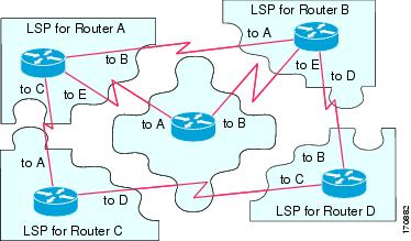
The figure below shows how the LSPs are used to create a network map. Imagine the network topology as a jigsaw puzzle. Each LSP (representing an IS) is considered one of the jigsaw pieces.
Note |
The figure below is applicable to all Level-1 routers in an area or to all Level-2 routers in a Level-2 subdomain. |
| Figure 3 | IS-IS Network Map |
The figure below shows each router in the IS-IS network with its fully updated link-state database, after the adjacencies have been formed among the neighbor routers.
Note |
The figure below is applicable to all Level-1 routers in an area or to all Level-2 routers in a Level-2 subdomain. |
| Figure 4 | IS-IS Routers with Synchronized LSPDBs |

IS-IS Overview of the Shortest Path Calculation
When the contents of the LSPDB change, each IS independently reruns a shortest path calculation. The algorithm is based on the well-known Dijkstra algorithm for finding the shortest paths along a directed graph where the ISs are the vertices of the graph and the links between the ISs are edges with a nonnegative weight. A two-way connectivity check is performed before considering a link between two ISs as part of the graph. This prevents the use of stale information in the LSPDB, for example, when one IS is no longer operating in the network but did not purge the set of LSPs that it generated before ceasing operation.
The output of the SPF is a set of tuples (destination, next hop). The destinations are protocol-specific; for example, they would be prefixes when the supported protocol is IP, NSAPs of end systems when the supported protocol is CLNP. Multiple equal-cost paths are supported, in which case multiple next hops would be associated with the same destination.
Independent SPFs are performed for each level supported by the IS. In cases in which the same destination is reachable by both Level-1 and Level-2 paths, the Level-1 path is preferred.
A Level-2 IS that indicates that it has one or more Level-2 neighbors in other areas may be used by Level-1 routers in the same area as the path of last resort, also called the default route. The Level-2 IS indicates its attachment to other areas by setting an attached bit (ATT) in its Level-1 LSP 0.
Note |
An IS can generate up to 256 LSPs at each level. The LSPs are identified by the numbers 0 through 255. LPS 0 has special properties, including the significance of the setting of the ATT bit to indicate attachment to other areas. When LPSs that are numbered 1 though 255 have the ATT bit set, it is not of significance. |
Where to Go Next
- To initially configure and enable IS-IS, see the "Configuring a Basic IS-IS Network" module.
- To customize IS-IS for your network design, see the "Customizing IS-IS for Your Network Design" module.
- To customize IS-IS for achieving fast convergence and scalability, see the following modules:
- To enhance IS-IS network security, see the "Enhancing Security in an IS-IS Network" module.
Additional References
Standards
| Standard |
Title |
|---|---|
| ISO 8473 |
CLNP, Connectionless Network Protocol |
| ISO 9542 |
ES-IS Routing Information Exchange Protocol |
| ISO/IEC 10589 |
IS-IS Protocol |
MIBs
| MIB |
MIBs Link |
|---|---|
| No new or modified MIBs are supported, and support for existing MIBs has not been modified. |
To locate and download MIBs for selected platforms, Cisco IOS releases, and feature sets, use Cisco MIB Locator found at the following URL: |
RFCs
| RFC |
Title |
|---|---|
| RFC 1195 |
http://www.ietf.org/rfc/rfc1195.txt Use of OSI IS-IS for Routing in TCP/IP and Dual Environments |
Technical Assistance
| Description |
Link |
|---|---|
| The Cisco Support and Documentation website provides online resources to download documentation, software, and tools. Use these resources to install and configure the software and to troubleshoot and resolve technical issues with Cisco products and technologies. Access to most tools on the Cisco Support and Documentation website requires a Cisco.com user ID and password. |
Glossary
area --A physically connected portion of a routing domain in which all routers are assigned a common area address. Also known as the Level-1 subdomain. A routing domain may consist of multiple areas that are reachable by traversing the Level-2 subdomain.
area address --The high-order octets of the Network Entity Title (NET) assigned to an IS. All ISs in the same Level-1 area are assigned the same area address.
CLNP --ISO Connectionless Network Protocol as defined in ISO 8473.
DIS --Designated Intermediate System. An IS elected by all the ISs operating on a multiaccess circuit at a given level to represent the multiaccess circuit. The DIS sends pseudonode LSPs on behalf of the circuit advertising adjacencies to all the ISs operating on that circuit.
domain --The portion of a network on which the IS-IS protocol is configured to operate. The routing domain consists of all Level-1 areas and the Level-2 subdomain.
ES --end system. An ES is any nonrouting host or node.
Integrated IS-IS --Extended form of IS-IS that supports multiple network protocols. Extensions have been defined in IETF documents, especially RFC 1195.
IS --intermediate system. OSI term for a router.
IP --Internet Protocol Version 4, also known as IPv4.
IPv6 --Internet Protocol Version 6.
IS-IS --Intermediate System-to-Intermediate System. Routing protocol as defined in ISO/IEC 10589.
Level-1 router --An IS that supports Level-1 routing for its assigned area.
Level-2 router --An IS that supports Level-2 routing.
Level-2 subdomain --All Level-2 capable routers in a domain and the links that interconnect them. Level-1 areas are interconnected via the Level-2 subdomain. For routing in a domain to work properly, the Level-2 subdomain must not be partitioned.
NET --Network Entity Title. An address assigned to an instance of the IS-IS protocol. The NET includes an area address, a system ID, and an N-selector. When multiple NETs are assigned to an IS-IS instance, only the area address portion of the NET may differ.
NSEL --N-selector. The least significant octet of a Network Entity Title. It is always assigned the value 00.
system ID --The part of the NET that immediately follows the area address. The field is 6 octets long.
Cisco and the Cisco Logo are trademarks of Cisco Systems, Inc. and/or its affiliates in the U.S. and other countries. A listing of Cisco's trademarks can be found at www.cisco.com/go/trademarks. Third party trademarks mentioned are the property of their respective owners. The use of the word partner does not imply a partnership relationship between Cisco and any other company. (1005R)
Any Internet Protocol (IP) addresses and phone numbers used in this document are not intended to be actual addresses and phone numbers. Any examples, command display output, network topology diagrams, and other figures included in the document are shown for illustrative purposes only. Any use of actual IP addresses or phone numbers in illustrative content is unintentional and coincidental.
 Feedback