- CEF Overview
- Configuring Basic Cisco Express Forwarding
- Enabling or Disabling CEF or dCEF
- Configuring a Load-Balancing Scheme
- Configuring Epochs
- Configuring CEF Consistency Checkers
- Configuring CEF Network Accounting
- Customizing the Display of Recorded CEF Events
- Customizing the Display of CEF Event Trace Messages
- SNMP CEF-MIB Support
- Cisco Express Forwarding Command Changes
- CEF Enhancements
- IPv6 CEF-Switched Tunnels
- Finding Feature Information
- Prerequisites for Cisco Express Forwarding
- Restrictions for Cisco Express Forwarding
- Information About Cisco Express Forwarding
Configuring Basic Cisco Express Forwarding
This module contains information about Cisco Express Forwarding and describes the required and optional tasks for verifying Cisco Express Forwarding and distributed Cisco Express Forwarding operation.
Cisco Express Forwarding is an advanced Layer 3 IP switching technology. It optimizes network performance and scalability for all kinds of networks: those that carry small amounts of traffic and those that carry large amounts of traffic in complex patterns, such as the Internet, and networks characterized by intensive web-based applications or interactive sessions.
- Finding Feature Information
- Prerequisites for Cisco Express Forwarding
- Restrictions for Cisco Express Forwarding
- Information About Cisco Express Forwarding
- How to Configure Basic Cisco Express Forwarding
- How to Verify Basic Cisco Express Forwarding
- Configuration Examples for Basic CEF
- Where to Go Next
- Additional References
- Feature Information for Basic CEF
- Glossary
Finding Feature Information
Your software release may not support all the features documented in this module. For the latest caveats and feature information, see Bug Search Tool and the release notes for your platform and software release. To find information about the features documented in this module, and to see a list of the releases in which each feature is supported, see the feature information table at the end of this module.
Use Cisco Feature Navigator to find information about platform support and Cisco software image support. To access Cisco Feature Navigator, go to www.cisco.com/go/cfn. An account on Cisco.com is not required.
Prerequisites for Cisco Express Forwarding
Cisco Express Forwarding requires a software image that includes Cisco Express Forwarding and IP routing enabled on the device.
Restrictions for Cisco Express Forwarding
Cisco Express Forwarding has the following restrictions:
- The Cisco 12000 Series Internet routers operate only in distributed Cisco Express Forwardingmode.
- If you enable Cisco Express Forwarding and then create an access list that uses the logkeyword, the packets that match the access list are not Cisco Express Forwarding switched. They are process switched. Logging disables Cisco Express Forwarding.
Information About Cisco Express Forwarding
If your network architecture requires that you disable or reenable Cisco Express Forwarding or distributed Cisco Express Forwarding switching and forwarding, change your load balancing scheme, refresh Cisco Express Forwarding tables, configure network accounting for Cisco Express Forwarding, or customize the display of Cisco Express Forwarding events, go to the "Related Documents" section for links to information on these tasks. Otherwise, you need do nothing more to configure Cisco Express Forwarding or distributed Cisco Express Forwarding operation in your network.
 Note |
Cisco Express Forwarding is supported on interfaces on which IEEE 802.1Q encapsulation has been enabled at the subinterface level. You no longer need to disable CEF operation on interfaces that are using IEEE 802.1Q encapsulation on VLAN subinterfaces. |
- Cisco Platform Support for CEF and dCEF
- Cisco Express Forwarding Benefits
- Main Components for CEF Operation
- CEF Operation Modes Central and Distributed
Cisco Platform Support for CEF and dCEF
Cisco Express Forwarding is enabled by default on most Cisco platforms running Cisco IOS software Release 12.0 and later. When Cisco Express Forwarding in enabled on a router, the Route Processor (RP) performs the express forwarding.
To find out if Cisco Express Forwarding is enabled by default on your platform, enter the show ip cefcommand. If Cisco Express Forwarding is enabled, you receive output that looks like the following:
Router# show ip cef
Prefix              Next Hop            Interface
[...]
10.2.61.8/24        192.168.100.1       FastEthernet1/0/0
                    192.168.101.1       FastEthernet6/1
[...]
If Cisco Express Forwarding is not enabled on your platform, the output for the show ip cefcommand looks like this:
Router# show ip cef
%CEF not running
Distributed Cisco Express Forwarding is enabled by default on the Catalyst 6500 series switch, the Cisco 7500 series router, and the Cisco 12000 Series Internet Router. When distributed Cisco Express Forwarding is enabled on your platform, the line cards perform the express forwarding.
If Cisco Express Forwarding is not enabled on your platform, use the ip cefcommand to enable Cisco Express Forwarding or the ip cef distributed command to enable distributed Cisco Express Forwarding.
Cisco Express Forwarding Benefits
- Improved performance--Cisco Express Forwarding is less CPU-intensive than fast switching route caching. As a result, more CPU processing power can be dedicated to Layer 3 services such as quality of service (QoS) and encryption.
- Scalability--Cisco Express Forwarding offers full switching capacity at each line card when distributed Cisco Express Forwarding mode is active. Distributed Cisco Express Forwarding is a distributed switching mechanism that scales linearly with the number of interface cards and the bandwidth installed in the router.
- Resiliency--Cisco Express Forwarding offers an unprecedented level of switching consistency and stability in large dynamic networks. In dynamic networks, fast-switched cache entries are frequently invalidated by routing changes. These changes can cause traffic to be process-switched through use of the routing table, rather than fast-switched through use of the route cache. Because the forwarding information base (FIB) lookup table contains all known routes that exist in the routing table, it eliminates the need for route cache maintenance and the steps involved with fast-switch or process-switch forwarding. Cisco Express Forwarding can switch traffic more efficiently than typical demand caching schemes.
Main Components for CEF Operation
Information conventionally stored in a route cache is stored in several data structures for Cisco Express Forwarding switching. The data structures provide optimized lookup for efficient packet forwarding. The two main components of Cisco Express Forwarding operation are the forwarding information base (FIB) and the adjacency tables.
The FIB is conceptually similar to a routing table or information base. A router uses this lookup table to make destination-based switching decisions during Cisco Express Forwarding operation. The FIB is updated as changes occur in the network and contains all routes known at the time. For more information on the FIB, see the "Cisco Express Forwarding Overview" module.
Adjacency tables maintain Layer 2 next-hop addresses for all FIB entries. For more information on adjacency tables, see the "Cisco Express Forwarding Overview" module.
This separation of the reachability information (in the Cisco Express Forwarding table) and the forwarding information (in the adjacency table), provides two main benefits:
- The adjacency table can be built separately from the Cisco Express Forwarding table, allowing both tables to build without the process switching of any packets.
- The MAC header rewrite used to forward a packet isn't stored in cache entries, so changes in a MAC header rewrite string do not require invalidation of cache entries.
CEF Operation Modes Central and Distributed
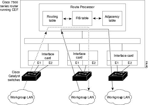
Central Cisco Express Forwarding Mode Operation
You can use central Cisco Express Forwarding mode when line cards are not available for Cisco Express Forwarding switching, when you need to use features not compatible with distributed Cisco Express Forwarding switching, or when you are running on a platform that is not a distributed platform. When central Cisco Express Forwarding mode is enabled, the Cisco Express Forwarding FIB and adjacency tables reside on the RP, and the RP performs the express forwarding.
The figure below shows the relationship between the routing table, the FIB, and the adjacency table during central Cisco Express Forwarding mode operation. The Catalyst switches forward traffic from workgroup LANs to a Cisco 7500 series router on the enterprise backbone running central Cisco Express Forwarding. The RP performs the express forwarding.
| Figure 1 | Central Cisco Express Forwarding Mode Operation |
Distributed Cisco Express Forwarding Mode Operation
For additional scalability, Cisco Express Forwarding runs in the form of distributed Cisco Express Forwarding on certain platforms by spreading processing tasks across two or more line cards. When distributed Cisco Express Forwarding mode is enabled, line cards maintain identical copies of the FIB and adjacency tables. The line cards perform the express forwarding between port adapters, relieving the RP of involvement in the switching operation, thus also enhancing system performance.
Distributed Cisco Express Forwarding uses an interprocess communication (IPC) mechanism to ensure synchronization of FIB tables and adjacency tables on the RP and line cards.
The figure below shows the relationship between the RP and line cards when distributed Cisco Express Forwarding mode is active.
| Figure 2 | Distributed Cisco Express Forwarding Mode Operation |
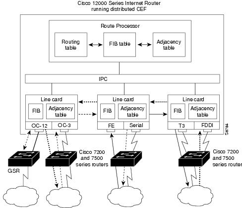
In the Cisco 12000 Series Internet Router, shown in the figure above, the line cards perform the switching. In other routers, where you can mix various types of cards in the same router, all cards might not support distributed Cisco Express Forwarding. When a line card that does not support distributed Cisco Express Forwarding receives a packet on one of these other routers, the line card forwards the packet to the next higher switching layer (the RP). This structure allows legacy interface processors to exist in the router with newer interface processors.
Note |
The Cisco 12000 Series Internet routers operate only in distributed Cisco Express Forwarding mode. |
How to Configure Basic Cisco Express Forwarding
There are no configuration tasks. Cisco Express Forwarding is enabled by default.
How to Verify Basic Cisco Express Forwarding
The following section contains instructions for verifying basic Cisco Express Forwarding or distributed Cisco Express Forwarding operation.
Before you perform the remaining tasks in this section you need to know which mode of Cisco Express Forwarding is running on your router. Cisco Express Forwarding is enabled by default on the Cisco 7100, 7200, and 7500 series routers. Distributed Cisco Express Forwarding is enabled by default on the Catalyst 6500 switch and on Cisco 12000 Series Internet routers. To determine if Cisco Express Forwarding or distributed Cisco Express Forwarding is enabled on your router, you can enter the show ip interface command and look for the entry "IP CEF switching enabled" or "IP Distributed CEF switching enabled." If Cisco Express Forwarding is not enabled, the entry in the command display would indicate that "IP CEF switching is disabled."
To verify basic Cisco Express Forwarding or distributed Cisco Express Forwarding operation, perform the following procedures and tasks:
- Determining How the Router Is Configured
- Verifying Cisco Express Forwarding Operation
- Verifying Distributed Cisco Express Forwarding Operation
- Interpreting Cisco Express Forwarding Command Output
Determining How the Router Is Configured
To determine if the router is configured for Cisco Express Forwarding or distributed Cisco Express Forwarding, perform the following task.
DETAILED STEPS
What to Do Next
Verifying Cisco Express Forwarding Operation
Perform the following tasks, in the order presented, to verify Cisco Express Forwarding operation on your router or to look for Cisco Express Forwarding operation information on your router:
See the Verifying Distributed Cisco Express Forwarding Operation for the tasks to perform for d istributed Cisco Express Forwarding operation.
- Verifying That Cisco Express Forwarding Switching Is Enabled
- Locating the Prefix in a Forwarding Table on the RP
- Finding the Cisco Express Forwarding Output Information
- Verifying the Adjacency or Next-Hop Information
Verifying That Cisco Express Forwarding Switching Is Enabled
To verify tha Cisco Express Forwarding switching is enabled on the input (ingress) interface on the router, perform the following steps.
DETAILED STEPS
| Step 1 | enable Use this command to enable privileged EXEC mode. You can also enter this command in user EXEC mode. Enter your password if prompted. For example: Example:
Router> enable
Router#
|
| Step 2 | show ip cef Use this command to verify that Cisco Express Forwarding is enabled globally. For example: Example:
Router# show ip cef
%CEF not running
If Cisco Express Forwarding is not running, use the ip cefcommand to enable Cisco Express Forwarding or the ip cef distributed command to enable distributed Cisco Express Forwarding. When Cisco Express Forwarding or distributed Cisco Express Forwarding is enabled, the show ip cefcommand shows a brief display of all FIB entries. |
| Step 3 | show cef interface type number detail Use this command to verify that Cisco Express Forwarding is enabled on a particular ingress interface. Look for the entry "IP CEF switching enabled." For example: Example: Router# show cef interface fastethernet 1/0/0 detail FastEthernet1/0/0 is up (if_number 9) Corresponding hwidb fast_if_number 9 Corresponding hwidb firstsw->if_number 9 Internet address is 10.2.61.8/24 ICMP redirects are always sent Per packet load-sharing is disabled IP unicast RPF check is disabled Inbound access list is not set Outbound access list is not set IP policy routing is disabled Hardware idb is FastEthernet1/0/0 Fast switching type 1, interface type 5 IP CEF switching enabled IP Feature Fast switching turbo vector IP Feature CEF switching turbo vector Input fast flags 0x0, Output fast flags 0x0 ifindex 7(7) Slot 1 Slot unit 0 VC -1 Transmit limit accumulator 0x48001A82 (0x48001A82) IP MTU 1500 |
| Step 4 | show ip interface type number Use this command to display the Cisco IOS switching methods enabled on an interface. For example: Example: router# show ip interface fastethernet 1/0/0 FastEthernet1/0/0 is up, line protocol is up IP fast switching is enabled IP fast switching on the same interface is enabled IP Flow switching is disabled IP CEF switching is enabled IP Distributed switching is enabled IP Fast switching turbo vector IP Normal CEF switching turbo vector IP multicast fast switching is enabled IP multicast distributed fast switching is disabled IP route-cache flags are Fast, Distributed, No CEF In the above output, the "IP CEF switching is enabled" entry indicates that Cisco Express Forwarding is enabled by default. The "No CEF" IP route-cache flag indicates that Cisco Express Forwarding is disabled because an administrator entered the no ip route-cache cefcommand on this interface. To enable Cisco Express Forwarding on this interface, enter the ip route-cache cef command. Once you do that, the "CEF" flag indicates that Cisco Express Forwarding is running. |
| Step 5 | exit Use this command to exit privileged EXEC mode. For example: Example:
Router# exit
Router> |
Locating the Prefix in a Forwarding Table on the RP
To locate the prefix in a forwarding table, perform the following steps.
DETAILED STEPS
| Step 1 | enable Use this command to enable privileged EXEC mode. You can also enter this command in user EXEC mode. Enter your password if prompted. For example: Example:
Router> enable
Router#
|
| Step 2 | show ip cef Use this command to show entries in the FIB and confirm that prefixes are listed in the FIB. For example: Example:
Router# show ip cef
Prefix              Next Hop            Interface
[...]
10.2.61.8/24        192.168.100.1       FastEthernet1/0/0
                    192.168.101.1       FastEthernet6/1
[...]
|
| Step 3 | show ip cef vrf vrf-name Use this command to locate prefixes in forwarding tables associated with Virtual Private Network (VPN) routing/forwarding table instances (VRFs). For example, this command shows prefixes in the left-hand column for a VRF named vpn1: Example:
Router# show ip cef vrf vpn1
Prefix              Next Hop            Interface
0.0.0.0/32          receive
10.1.0.0/8          10.0.0.1            Ethernet1/3
10.2.0.0/8          10.0.0.2            POS6/0
10.0.0.0/8          attached            Ethernet1/3
10.0.0.0/32         receive
10.0.0.1/32         10.0.0.1            Ethernet1/3
10.0.0.2/32         receive
10.255.255.255/32   receive
10.3.0.0/8          10.0.0.2            POS6/0
10.50.0.0/24        receive
255.255.255.255/32  receive
|
| Step 4 | Repeat Step 2 as many times as required to locate the prefix. If Cisco Express Forwarding is in a VPN, you might need to look at multiple VRFs. |
| Step 5 | exit Use this command to exit privileged EXEC mode. For example: Example:
Router# exit
Router> |
Finding the Cisco Express Forwarding Output Information
To find the Cisco Express Forwarding output information associated with the prefix on the RP, perform the following steps.
DETAILED STEPS
| Step 1 | enable Use this command to enable privileged EXEC mode. You can also enter this command in user EXEC mode. Enter your password if prompted. For example: Example:
Router> enable
Router#
|
| Step 2 | show ip cef Use this command to confirm that the prefix is listed in the FIB. For example: Example: router# show ip cef Prefix Next Hop Interface 0.0.0.0/32 receive 192.168.0.0/30 attached Serial2/0/0:1 192.168.0.0/32 receive 10.2.61.8/24 192.168.100.1 FastEthernet1/0/0 |
| Step 3 | show ip cef prefix Use this command to display the prefix entry in the FIB for centralized Cisco Express Forwarding. For example: Example:
Router# show ip cef 10.2.61.8 255.255.255.0
10.0.0.0/8, version 72, per-destination sharing
0 packets, 0 bytes
via 192.168.100.1, 0 dependencies, recursive
traffic share 1
next hop 192.168.100.1, FastEthernet1/0/0 via 192.168.100.1/32
valid adjacency
via 192.168.101.1, 0 dependencies, recursive
traffic share 1
next hop 192.168.101.1, FastEthernet6/1 via 192.168.101.1/32
valid adjacency
0 packets, 0 bytes switched through the prefix
|
| Step 4 | show ip cef prefix detail Use this command to show more detail for each of the active paths associated with a destination prefix. For example: Example:
Router# show ip cef 10.0.0.0 detail
10.0.0.0/8, version 72, per-destination sharing
0 packets, 0 bytes
via 192.168.100.1, 0 dependencies, recursive
traffic share 1
next hop 192.168.100.1, FastEthernet1/0/0 via 192.168.100.1/32
valid adjacency
via 192.168.101.1, 0 dependencies, recursive
traffic share 1
next hop 192.168.101.1, FastEthernet6/1 via 192.168.101.1/32
valid adjacency
0 packets, 0 bytes switched through the prefix
|
| Step 5 | exit Use this command to exit privileged EXEC mode. For example: Example:
Router# exit
Router> |
Verifying the Adjacency or Next-Hop Information
To verify the adjacency or next-hop information on the RP, perform the following steps.
Adjacencies are added to the adjacency table when the adjacency is
- Indirectly configured manually
- Dynamically discovered through ARP
- Created when a routing protocol, for example, Border Gateway Protocol (BGP) or Open Shortest Path First (OSPF), forms a neighbor relationship
For more information on adjacencies, see the "Cisco Express Forwarding Overview" module.
DETAILED STEPS
| Step 1 | enable Use this command to enable privileged EXEC mode. You can also enter this command in user EXEC mode. Enter your password if prompted. For example: Example:
Router> enable
Router#
|
| Step 2 | show ip cef Use this command to find the output interface. For example: Example:
router# show ip cef
Prefix              Next Hop            Interface
0.0.0.0/32          receive
192.168.0.0/30      attached            Serial2/0/0:1
192.168.0.0/32      receive
10.2.61.8/24        192.168.100.1       FastEthernet1/0/0
In this example, the output interface for the prefix 10.2.61.8/24 is FastEthernet 1/0/0, and the next hop address is 192.168.100.1. |
| Step 3 | show adjacency detail Use this command to display adjacency information, including Layer 2 information. For example: Example:
Router# show adjacency detail
Protocol Interface Address
IP Ethernet1/0/0 10.2.61.8(7)
0 packets, 0 bytes
00107BC30D5C
00500B32D8200800
ARP 02:01:49
The encapsulation string 00107BC30D5C00500B32D8200800 is that of an adjacency used for traffic switched out of a router on an Ethernet link by means of Ethernet II encapsulation. |
| Step 4 | show adjacency summary Use this command to display Cisco Express Forwarding adjacency table summary information. For example: Example:
Router# show adjacency summary
Adjacency Table has 1 adjacency
Interface Adjacency Count
Ethernet1/0/0 1
|
| Step 5 | show adjacency type number Use this command to display adjacency information for a particular interface. For example: Example:
Router# show adjacency fastethernet 2/3
Protocol Interface Address
IP FastEthernet2/3 172.20.52.1(3045)
IP FastEthernet2/3 172.20.52.22(11)
|
| Step 6 | show ip cef exact-route source-address destination-address Use this command to display the exact route for a source-destination IP address pair and verify the next-hop address. For example: Example:
Router# show ip cef exact-route 10.1.1.1 10.2.61.8
10.1.1.1 -> 10.2.61.8 :FastEthernet1/0/0 (next hop 192.168.100.1)
In this example, the exact route from source address 10.1.1.1 to destination address 10.2.61.8 is through interface Ethernet1/0/0 to next hop address 192.168.100.1. |
| Step 7 | exit Use this command to exit privileged EXEC mode. For example: Example:
Router# exit
Router> |
Verifying Distributed Cisco Express Forwarding Operation
Perform the following tasks, in the order presented, to verify distributed Cisco Express Forwarding operation on your router:
- Cisco Express Forwarding Command Syntax on Line Cards
- Verifying That dCEF Switching Is Enabled
- Locating the Prefix in a Forwarding Table on a Line Card
- Finding the Distributed Cisco Express Forwarding Output Information
- Verifying the Adjacency or Next-Hop Information on a Line Card
Cisco Express Forwarding Command Syntax on Line Cards
To perform tasks on router line cards, you need to use the following syntax: execute-on[slot slot-number | all] command. The execute-on commands apply only to the Cisco 12000 Series Internet routers and the Cisco 7500 series routers. The all keyword is available only on the Cisco 12000 Series Internet routers.
For example, use the following command to display FIB entries on the line cards in the first slot:
Router# execute-on 0 show ip cef
To perform tasks on a Catalyst 6500 series switch, you use the following syntax: remote command module mod command. For example:
Router# remote command module 2 show ip cef
The tasks in this document apply to the Cisco 7500 series and Cisco 12000 Series Internet routers.
Verifying That dCEF Switching Is Enabled
To verify that distributed Cisco Express Forwarding switching is enabled on the input (ingress) interface on the line card, perform the following steps.
DETAILED STEPS
| Step 1 | enable Use this command to enable privileged EXEC mode. You can also enter this command in user EXEC mode. Enter your password if prompted. For example: Example:
Router> enable
Router#
|
| Step 2 | show ip cef Use this command to verify that Cisco Express Forwarding is enabled globally. For example: Example:
Router# show ip cef
%CEF not running
If Cisco Express Forwarding is not running, use the ip cefcommand to enable (central) Cisco Express Forwarding or the ip cef distributed command to enable distributed Cisco Express Forwarding. When Cisco Express Forwarding or distributed Cisco Express Forwarding is enabled, the show ip cefcommand shows a brief display of all FIB entries. |
| Step 3 | execute-on slot slot-number show ip cef prefix Use this command to verify information about interfaces on a line card. For example: Example: Router# execute-on slot 0 show ip cef 192.68.0.0 255.255.255.0 show ip cef 192.68.0.0 255.255.255.0 from slot 0: 192.68.0.0/24, version 19, epoch 0, attached, connected 0 packets, 0 bytes via Ethernet5/0/0, 0 dependencies valid glean adjacency |
| Step 4 | exit Use this command to exit privileged EXEC mode. For example: Example:
Router# exit
Router> |
Locating the Prefix in a Forwarding Table on a Line Card
To locate the prefix in a forwarding table on the line card, perform the following steps.
DETAILED STEPS
| Step 1 | enable Use this command to enable privileged EXEC mode. You can also enter this command in user EXEC mode. Enter your password if prompted. For example: Example:
Router> enable
Router#
|
| Step 2 | execute-on slot slot-number show ip cef Use this command to show entries in the FIB on the line card and confirm that prefixes are listed in the FIB. For example: Example:
Router# execute-on slot 0 show ip cef
show ip cef from slot 0:
Prefix Next Hop Interface
0.0.0.0/0 192.168.0.1 Ethernet5/0/0
0.0.0.0/32 receive
192.168.0.0/24 attached Ethernet5/0/0
192.168.0.0/32 receive
192.168.0.1/32 192.168.0.1 Ethernet5/0/0
192.168.0.141/32 receive
192.168.0.255/32 receive
239.224.0.0/4 drop
239.224.0.0/24 receive
255.255.255.255/32 receive
|
| Step 3 | execute-on all show ip cef vrf vrf-name Use this command to locate prefixes in forwarding tables associated with Virtual Private Network (VPN) routing/forwarding instances (VRFs). For example, this command shows prefixes in the left-hand column for a VRF named vpn1: Example:
Router# execute-on all show ip cef vrf vpn1
Prefix Next Hop Interface
0.0.0.0/32 receive
10.1.0.0/8 10.0.0.1 Ethernet1/3
10.2.0.0/8 10.0.0.2 POS6/0
10.0.0.0/8 attached Ethernet1/3
10.0.0.0/32 receive
10.0.0.1/32 10.0.0.1 Ethernet1/3
10.0.0.2/32 receive
10.255.255.255/32 receive
10.3.0.0/8 10.0.0.2 POS6/0
10.50.0.0/24 receive
255.255.255.255/32 receive
|
| Step 4 | Repeat Step 2 as many times as required to locate the prefix. If distributed Cisco Express Forwarding is in a VPN, you might need to look at multiple VRFs. |
| Step 5 | show ip cef Use this command to show entries in the FIB on the RP and to verify that the FIB on the line card is synchronized with the FIB maintained by the router. For example: Example:
Router# show ip cef
Prefix Next Hop Interface
[...]
10.2.61.8/24 192.168.100.1 FastEthernet1/0/0
192.168.101.1 FastEthernet6/1
[...]
Compare the prefixes, next hops, and interfaces in this output with those in the output from Step 1 to verify that FIB on the line card is synchronized with the FIB maintained by the router. |
| Step 6 | exit Use this command to exit privileged EXEC mode. For example: Example:
Router# exit
Router> |
Finding the Distributed Cisco Express Forwarding Output Information
To find the distributed Cisco Express Forwarding output information associated with the prefix on a line card, perform the following steps.
DETAILED STEPS
| Step 1 | enable Use this command to enable privileged EXEC mode. You can also enter this command in user EXEC mode. Enter your password if prompted. For example: Example:
Router> enable
Router#
|
| Step 2 | execute-on slot slot-number show ip cef Use this command to confirm that the prefix is listed in the FIB. For example: Example: Router# execute-on slot 0 show ip cef show ip cef from slot 0: Prefix Next Hop Interface 0.0.0.0/0 192.168.0.1 Ethernet5/0/0 0.0.0.0/32 receive 192.168.0.0/24 attached Ethernet5/0/0 192.168.0.0/32 receive 192.168.0.1/32 192.168.0.1 Ethernet5/0/0 192.168.0.141/32 receive 192.168.0.255/32 receive 239.224.0.0/4 drop 239.224.0.0/24 receive 255.255.255.255/32 receive |
| Step 3 | execute-on slot slot-number show ip cef prefix Use this command to display the prefix entry in the FIB on a line card. For example: Example:
Router# execute
-on slot 3 show ip cef 192.68.0.0 255.255.255.0
show ip cef 192.168.0.0 255.255.255.0 from slot 0:
192.168.0.0/24, version 19, epoch 0, attached, connected
0 packets, 0 bytes
via Ethernet5/0/0, 0 dependencies
valid glean adjacency
|
| Step 4 | execute-on slot slot-number show ip cef prefix detail Use this command to show more detail for each of the active paths associated with a destination prefix on a line card. For example: Example:
Router# execute-on slot 0 show ip cef 10.24.48.32 detail
show ip cef 192.168.0.0 255.255.255.0 from slot 0:
192.168.0.0/24, version 19, epoch 0, attached, connected
0 packets, 0 bytes
via Ethernet5/0/0, 0 dependencies
valid glean adjacency
|
| Step 5 | exit Use this command to exit privileged EXEC mode. For example: Example:
Router# exit
Router> |
Verifying the Adjacency or Next-Hop Information on a Line Card
To verify the adjacency or next-hop information on a line card, perform the following steps.
Cisco Express Forwarding adds an adjacency to the adjacency table when the adjacency is
- Indirectly configured manually
- Dynamically discovered through ARP
- Created when a routing protocol, for example, BGP or OSPF, forms a neighbor relationship
For more information on adjacencies, see the Cisco Express Forwarding Overview module.
DETAILED STEPS
Interpreting Cisco Express Forwarding Command Output
Perform the following tasks to interpret information in Cisco Express Forwarding command output:
Verifying That CEF Information Looks As Expected
Perform the following tasks to verify that the Cisco Express Forwarding information looks as you expected.
DETAILED STEPS
Interpreting MPLS Information in CEF Output
Perform the following steps to interpret Multiprotocol Label Switching (MPLS) information in Cisco Express Forwarding output.
Cisco Express Forwarding interacts with a label switched path (LSP) primarily at the beginning and end of the LSP--that is, on label imposition (IP packet to MPLS packet) and label disposition (MPLS packet to IP packet). Output from Cisco Express Forwarding commands should show these processes.
The Cisco implementation of MPLS leverages the advantages of Cisco Express Forwarding. When you use a router as an MPLS edge router, Cisco Express Forwarding identifies the route for incoming packets and finds the label to apply to the packet.
However, when you use a router as a label switch router (LSR), tables from the MPLS label forwarding information base (LFIB) are used to switch MPLS packets. These tables are distributed to the Versatile Interface Processor (VIP) or to line cards in the same way that the FIB tables are distributed in Cisco Express Forwarding.
A customer-site VRF contains all the routes available to the site from the VPNs to which it belongs. VPN routing information is stored in the IP routing table and in the Cisco Express Forwarding table for each VRF. A separate set of tables is maintained for each VRF, which prevents information from being forwarded outside a VPN and prevents packets that are outside a VPN from being forwarded to a router within the VPN. Based on the routing information stored in the VRF IP routing table and the VRF Cisco Express Forwarding table, packets are forwarded to their destinations. Output from Cisco Express Forwarding commands shows details from the VRF Cisco Express Forwarding tables.
DETAILED STEPS
| Step 1 | enable Use this command to enable privileged EXEC mode. You can also enter this command in user EXEC mode. Enter your password if prompted. For example: Example:
Router> enable
Router#
|
| Step 2 | show ip cef vrf vrf-name detail Use this command to display detailed information from the Cisco Express Forwarding forwarding table that is associated with a VRF. For example: Example:
Router# show ip cef vrf vpn1 detail
IP CEF with switching (Table Version 10), flags=0x0
8 routes, 0 reresolve, 0 unresolved (0 old, 0 new)
46 leaves, 51 nodes, 54640 bytes, 361 inserts, 315 invalidations
0 load sharing elements, 0 bytes, 0 references
universal per-destination load sharing algorithm, id F968AD29
5 CEF resets, 38 revisions of existing leaves
refcounts: 1400 leaf, 1392 node
Adjacency Table has 2 adjacencies
0.0.0.0/32, version 0, receive
192.168.6.0/24, version 9, cached adjacency to Serial0/1.1
0 packets, 0 bytes
The following section of the Cisco Express Forwarding output provides MPLS information for the first adjacency. The "tag rewrite" is an equivalent of a Cisco Express Forwarding adjacency. Look at the tags imposed field. The first tag {20} is the tag used to reach the next hop, 10.1.1.13. The second tag {30} is the tag advertised to the local provider edge (PE) router by the remote PE router. Example:
tag information set
local tag: VPN-route-head
fast tag rewrite with Se0/1.1, point2point, tags imposed: {20 30}
via 10.10.10.6, 0 dependencies, recursive
next hop 10.1.1.13, Serial0/1.1 via 10.10.10.6
valid cached adjacency
tag rewrite with Se0/1.1, point2point, tags imposed: {20 30}
The following section of the output provides information about the second adjacency. For the second adjacency, no tag rewrite occurs as indicated by the entry "tag rewrite with , ," and MPLS tags are not imposed on the packet indicated by the entry "tags imposed : {}." The router also discards this packet indicated by the entry "valid discard adjacency." Example:
192.168.4.0/24, version 6, attached, connected
0 packets, 0 bytes
tag information set
local tag: 28
via Loopback102, 0 dependencies
valid discard adjacency
tag rewrite with , , tags imposed: {}
192.168.4.0/32, version 4, receive
192.168.4.1/32, version 3, receive
192.168.4.255/32, version 5, receive
192.168.0.0/24, version 2, receive
255.255.255.255/32, version 1, receive
|
| Step 3 | exit Use this command to exit to user EXEC mode. For example: Example:
Router# exit
Router> |
Configuration Examples for Basic CEF
There are no configuration examples for Cisco Express Forwarding. Cisco Express Forwarding is enabled by default.
Where to Go Next
If you want to disable Cisco Express Forwarding or distributed Cisco Express Forwarding operation, refer to Enabling or Disabling Cisco Express Forwarding or distributed Cisco Express Forwarding to Customize Switching/Forwarding for Dynamic Networks.
Additional References
Related Documents
| Related Topic |
Document Title |
|---|---|
| Cisco IOS commands |
|
| IP switching commands: complete command syntax, command modes, command history, defaults, usage guidelines, and examples. |
Cisco IOS IP Switching Command Reference |
| Overview of the Cisco Express Forwarding feature |
Cisco Express Forwarding Overview |
| Tasks for enabling or disabling Cisco Express Forwarding or distributed Cisco Express Forwarding |
Enabling or Disabling Cisco Express Forwarding or distributed Cisco Express Forwarding to Customize Switching/Forwarding for Dynamic Networks |
| Tasks for configuring a load-balancing scheme for Cisco Express Forwarding |
Configuring a Load-Balancing Scheme for Cisco Express Forwarding Traffic |
| Tasks for configuring Cisco Express Forwarding consistency checkers |
Configuring Cisco Express Forwarding Consistency Checkers for Route Processors and Line Cards |
| Tasks for configuring epochs for Cisco Express Forwarding tables |
Configuring Epochs to Clear and Rebuild Cisco Express Forwarding and Adjacency Tables |
| Tasks for configuring and verifying Cisco Express Forwarding network accounting |
Configuring Cisco Express Forwarding Network Accounting |
| Tasks for customizing the display of recorded Cisco Express Forwarding events |
Customizing the Display of Recorded Cisco Express Forwarding Events |
| Verification steps for Cisco Express Forwarding switching |
http://www.cisco.com/en/US/products/sw/iosswrel/ps1828/products_tech_note09186a00801e1e46.shtml How to Verify Cisco Express Forwarding Switching |
| Troubleshooting tips for incomplete adjacencies |
http://www.cisco.com/en/US/tech/tk827/tk831/technologies_tech_note09186a0080094303.shtml Troubleshooting Incomplete Adjacencies with CEF |
| Description and use of the Cisco Express Forwarding consistency checkers available for the Cisco 7500 and 12000 series routers |
Troubleshooting Prefix Inconsistencies with Cisco Express Forwarding |
| Information about troubleshooting Cisco Express Forwarding routing loops and suboptimal routing |
|
| Causes of common Cisco Express Forwarding-related error messages on platforms running distributed Cisco Express Forwarding switching (Cisco 7500 series routers and Cisco 12000 Series Internet routers) and how to troubleshoot them |
Troubleshooting Cisco Express Forwarding-Related Error Messages |
| Explanation of and troubleshooting information for the Cisco IOS software implementation of Layer 3 load balancing across multiple parallel links when Cisco Express Forwarding is used |
Troubleshooting Load Balancing Over Parallel Links Using Cisco Express Forwarding |
| QoS features that require Cisco Express Forwarding |
Standards
| Standard |
Title |
|---|---|
| No new or modified standards are supported by this feature, and support for existing standards has not been modified by this feature. |
-- |
MIBs
| MIB |
MIBs Link |
|---|---|
| No new or modified MIBs are supported by this feature, and support for existing MIBs has not been modified by this feature. |
To locate and download MIBs for selected platforms, Cisco IOS releases, and feature sets, use Cisco MIB Locator found at the following URL: |
RFCs
| RFC |
Title |
|---|---|
| No new or modified RFCs are supported by this feature, and support for existing RFCs has not been modified by this feature. |
-- |
Technical Assistance
| Description |
Link |
|---|---|
| The Cisco Support and Documentation website provides online resources to download documentation, software, and tools. Use these resources to install and configure the software and to troubleshoot and resolve technical issues with Cisco products and technologies. Access to most tools on the Cisco Support and Documentation website requires a Cisco.com user ID and password. |
Feature Information for Basic CEF
The following table provides release information about the feature or features described in this module. This table lists only the software release that introduced support for a given feature in a given software release train. Unless noted otherwise, subsequent releases of that software release train also support that feature.
Use Cisco Feature Navigator to find information about platform support and Cisco software image support. To access Cisco Feature Navigator, go to www.cisco.com/go/cfn. An account on Cisco.com is not required.
| Table 1 | Feature Information for Configuring Basic Cisco Express Forwarding |
| Feature Name |
Releases |
Feature Configuration Information |
|---|---|---|
| CEF/dCEF - Cisco Express Forwarding |
Cisco IOS XE Release 2.1 15.0(1)S |
This feature was introduced on Cisco ASR 1000 Series Routers. This feature was integrated into Cisco IOS Release 15.0(1)S. |
Glossary
adjacency --A relationship formed between selected neighboring routers and end nodes for the purpose of exchanging routing information. Adjacency is based upon the use of a common media segment by the routers and nodes involved.
Cisco Express Forwarding --A Layer 3 switching technology. Cisco Express Forwarding can also refer to central Cisco Express Forwarding mode, one of two modes of Cisco Express Forwarding operation. Cisco Express Forwarding enables a Route Processor (RP) to perform express forwarding. Distributed Cisco Express Forwarding is the other mode of Cisco Express Forwarding operation.
distributed Cisco Express Forwarding --A type of Cisco Express Forwarding switching in which line cards (such as Versatile Interface Processor (VIP) line cards) maintain identical copies of the forwarding information base (FIB) and adjacency tables. The line cards perform the express forwarding between port adapters; this relieves the Route Switch Processor of involvement in the switching operation.
FIB --forwarding information base. A component of Cisco Express Forwarding. The router uses the FIB lookup table to make destination-based switching decisions during Cisco Express Forwarding operation. The router maintains a mirror image of the forwarding information in an IP routing table.
IPC --interprocess communication. The mechanism that enables the distribution of Cisco Express Forwarding tables from the Route Switch Processor (RSP) to the line card when the router is operating in distributed Cisco Express Forwarding mode.
label disposition --The removal of Multiprotocol Label Switching (MPLS) headers at the edge of a network. In MPLS label disposition, packets arrive on a router as MPLS packets and, with the headers removed, are transmitted as IP packets.
label imposition --The action of putting a label on a packet.
LER --label edge router. A router that performs label imposition.
LFIB --label forwarding information base. The data structure used by switching functions to switch labeled packets.
LIB --label information base. A database used by a label switch router (LSR) to store labels learned from other LSRs, as well as labels assigned by the local LSR.
line card --A general term for an interface processor that can be used in various Cisco products. For example, a Versatile Interface Processor (VIP) is a line card for the Cisco 7500 series router.
LSP --label switched path. A sequence of hops (Router 0...Router n). A packet travels from R0 to Rn by means of label switching mechanisms. An LSP can be chosen dynamically, based on normal routing mechanisms, or it can be configured manually.
LSR --label switch router. A Layer 3 router that forwards a packet based on the value of a label encapsulated in the packet.
MPLS --Multiprotocol Label Switching. An emerging industry standard for the forwarding of packets along the normal routing paths (sometimes called MPLS hop-by-hop forwarding).
prefix --The network address portion of an IP address. A prefix is specified by a network and mask and is generally represented in the format network/mask. The mask indicates which bits are the network bits. For example, 1.0.0.0/16 means that the first 16 bits of the IP address are masked, making them the network bits. The remaining bits are the host bits. In this example, the network number is 10.0.
RIB --Routing Information Base. A central repository of routes that contains Layer 3 reachability information and destination IP addresses or prefixes. The RIB is also known as the routing table.
RP --Route Processor. The processor module in the Cisco 7000 series routers that contains the CPU, system software, and most of the memory components that are used in the router. It is sometimes called a supervisory processor.
RSP --Route Switch Processor. The processor module used in the Cisco 7500 series routers that integrates the functions of the Route Processor (RP) and the Switch Processor (SP).
SP --Switch Processor. Cisco 7000 series processor module that acts as the administrator for all CxBus activities. It is also sometimes called a CiscoBus controller.
VIP --Versatile Interface Processor. An interface card used in Cisco 7000 and Cisco 7500 series routers. The VIP provides multilayer switching and runs Cisco IOS.
VPN --Virtual Private Network. The result of a router configuration that enables IP traffic to use tunneling to travel securely over a public TCP/IP network.
VRF --A Virtual Private Network (VPN) routing/forwarding instance. A VRF consists of an IP routing table, a derived forwarding table, a set of interfaces that use the forwarding table, and a set of rules and routing protocols that determine what goes into the forwarding table. In general, a VRF includes the routing information that defines a customer VPN site that is attached to a PE router.
Cisco and the Cisco logo are trademarks or registered trademarks of Cisco and/or its affiliates in the U.S. and other countries. To view a list of Cisco trademarks, go to this URL: www.cisco.com/go/trademarks. Third-party trademarks mentioned are the property of their respective owners. The use of the word partner does not imply a partnership relationship between Cisco and any other company. (1110R)
Any Internet Protocol (IP) addresses and phone numbers used in this document are not intended to be actual addresses and phone numbers. Any examples, command display output, network topology diagrams, and other figures included in the document are shown for illustrative purposes only. Any use of actual IP addresses or phone numbers in illustrative content is unintentional and coincidental.
 Feedback