- IPv6 Addressing and Basic Connectivity
- IPv6 Anycast Address
- IPv6 Switching: Cisco Express Forwarding and Distributed Cisco Express Forwarding Support
- Unicast Reverse Path Forwarding for IPv6
- IPv6 Services: AAAA DNS Lookups over an IPv4 Transport
- IPv6 MTU Path Discovery
- ICMP for IPv6
- ICMP for IPv6 Redirect
- IPv6 Neighbor Discovery
- IPv6 Neighbor Discovery Cache
- Enhanced IPv6 Neighbor Discovery Cache Management
- IPv6 Default Router Preference
- IPv6 Stateless Autoconfiguration
- IPv6 RFCs
- Finding Feature Information
- Restrictions for IPv6 Addressing and Basic Connectivity
- Information About IPv6 Addressing and Basic Connectivity
- IPv6 for Cisco Software
- Large IPv6 Address Space for Unique Addresses
- IPv6 Address Formats
- IPv6 Address Output Display
- Simplified IPv6 Packet Header
- DNS for IPv6
- Cisco Discovery Protocol IPv6 Address Support
- IPv6 Prefix Aggregation
- IPv6 Site Multihoming
- IPv6 Data Links
- Routed Bridge Encapsulation for IPv6
- IPv6 Redirect Messages
- IPv6 on BVI Interfaces for Bridging and Routing
- Dual IPv4 and IPv6 Protocol Stacks
- How to Configure IPv6 Addressing and Basic Connectivity
- Configuration Examples for IPv6 Addressing and Basic Connectivity
- Additional References
- Feature Information for IPv6 Addressing and Basic Connectivity
IPv6 Addressing and Basic Connectivity
Internet Protocol version 6 (IPv6) expands the number of network address bits from 32 bits (in IPv4) to 128 bits, which provides more than enough globally unique IP addresses for every networked device on the planet. The unlimited address space provided by IPv6 allows Cisco to deliver more and newer applications and services with reliability, improved user experience, and increased security.
Implementing basic IPv6 connectivity in the Cisco software consists of assigning IPv6 addresses to individual device interfaces. IPv6 traffic forwarding can be enabled globally, and Cisco Express Forwarding switching for IPv6 can also be enabled. The user can enhance basic connectivity functionality by configuring support for AAAA record types in the Domain Name System (DNS) name-to-address and address-to-name lookup processes, and by managing IPv6 neighbor discovery.
- Finding Feature Information
- Restrictions for IPv6 Addressing and Basic Connectivity
- Information About IPv6 Addressing and Basic Connectivity
- How to Configure IPv6 Addressing and Basic Connectivity
- Configuration Examples for IPv6 Addressing and Basic Connectivity
- Additional References
- Feature Information for IPv6 Addressing and Basic Connectivity
Finding Feature Information
Your software release may not support all the features documented in this module. For the latest caveats and feature information, see Bug Search Tool and the release notes for your platform and software release. To find information about the features documented in this module, and to see a list of the releases in which each feature is supported, see the feature information table at the end of this module.
Use Cisco Feature Navigator to find information about platform support and Cisco software image support. To access Cisco Feature Navigator, go to www.cisco.com/go/cfn. An account on Cisco.com is not required.
Restrictions for IPv6 Addressing and Basic Connectivity
-
IPv6 packets are transparent to Layer 2 LAN devices because the devices do not examine Layer 3 packet information before forwarding IPv6 frames. Therefore, IPv6 hosts can be directly attached to Layer 2 LAN devices.
- Multiple IPv6 global addresses within the same prefix can be configured on an interface. However, multiple IPv6 link-local addresses on an interface are not supported.
- Because RFC 3879 obsoletes the use of site-local addresses, configuration of private IPv6 addresses should be done following the recommendations of unique local addressing (ULA) in RFC 4193.
Information About IPv6 Addressing and Basic Connectivity
- IPv6 for Cisco Software
- Large IPv6 Address Space for Unique Addresses
- IPv6 Address Formats
- IPv6 Address Output Display
- Simplified IPv6 Packet Header
- DNS for IPv6
- Cisco Discovery Protocol IPv6 Address Support
- IPv6 Prefix Aggregation
- IPv6 Site Multihoming
- IPv6 Data Links
- Routed Bridge Encapsulation for IPv6
- IPv6 Redirect Messages
- IPv6 on BVI Interfaces for Bridging and Routing
- Dual IPv4 and IPv6 Protocol Stacks
IPv6 for Cisco Software
IPv6, formerly named IPng (next generation), is the latest version of the Internet Protocol (IP). IP is a packet-based protocol used to exchange data, voice, and video traffic over digital networks. IPv6 was proposed when the 32-bit addressing scheme of IP version 4 (IPv4) proved to be inadequate to meet the demands of Internet growth. IPv6 is based on IP but with a much larger address space and improvements such as a simplified main header and extension headers. IPv6 is described in RFC 2460, Internet Protocol, Version 6 (IPv6) Specification, issued by the Internet Engineering Task Force (IETF). Further RFCs describe the architecture and services supported by IPv6.
The architecture of IPv6 has been designed to allow existing IPv4 users to transition easily to IPv6 while providing services such as end-to-end security, quality of service (QoS), and globally unique addresses. The larger IPv6 address space allows networks to scale and provide global reachability. The simplified IPv6 packet header format handles packets more efficiently. IPv6 prefix aggregation, simplified network renumbering, and IPv6 site multihoming capabilities provide an IPv6 addressing hierarchy that allows for more efficient routing. IPv6 supports widely deployed routing protocols such as Routing Information Protocol (RIP), Integrated Intermediate System-to-Intermediate System (IS-IS), Open Shortest Path First version 3 (OSPFv3), and multiprotocol Border Gateway Protocol (BGP). Other available features include stateless autoconfiguration, enhanced support for Mobile IPv6, and an increased number of multicast addresses.
Large IPv6 Address Space for Unique Addresses
The primary motivation for IPv6 is the need to meet the demand for globally unique IP addresses. IPv6 quadruples the number of network address bits from 32 bits (in IPv4) to 128 bits, which provides more than enough globally unique IP addresses for every networked device on the planet. By being globally unique, IPv6 addresses inherently enable global reachability and end-to-end security for networked devices, functionality that is crucial to the applications and services that are driving the demand for the addresses. Additionally, the flexibility of the IPv6 address space reduces the need for private addresses; therefore, IPv6 enables new application protocols that do not require special processing by border devices at the edge of networks.
IPv6 Address Formats
IPv6 addresses are represented as a series of 16-bit hexadecimal fields separated by colons (:) in the format: x:x:x:x:x:x:x:x. Following are two examples of IPv6 addresses:
2001:DB8:7654:3210:FEDC:BA98:7654:3210
2001:DB8:0:0:8:800:200C:417A
IPv6 addresses commonly contain successive hexadecimal fields of zeros. Two colons (::) may be used to compress successive hexadecimal fields of zeros at the beginning, middle, or end of an IPv6 address (the colons represent successive hexadecimal fields of zeros). The table below lists compressed IPv6 address formats.
A double colon may be used as part of the ipv6-address argument when consecutive 16-bit values are denoted as zero. You can configure multiple IPv6 addresses per interfaces, but only one link-local address.
 Note |
Two colons (::) can be used only once in an IPv6 address to represent the longest successive hexadecimal fields of zeros. The hexadecimal letters in IPv6 addresses are not case-sensitive. |
| Table 1 | Compressed IPv6 Address Formats |
| IPv6 Address Type |
Preferred Format |
Compressed Format |
|---|---|---|
| Unicast |
2001:0:0:0:DB8:800:200C:417A |
2001::DB8:800:200C:417A |
| Multicast |
FF01:0:0:0:0:0:0:101 |
FF01::101 |
| Loopback |
0:0:0:0:0:0:0:1 |
::1 |
| Unspecified |
0:0:0:0:0:0:0:0 |
:: |
The loopback address listed in the table above may be used by a node to send an IPv6 packet to itself. The loopback address in IPv6 functions the same as the loopback address in IPv4 (127.0.0.1).
 Note |
The IPv6 loopback address cannot be assigned to a physical interface. A packet that has the IPv6 loopback address as its source or destination address must remain within the node that created the packet. IPv6 devices do not forward packets that have the IPv6 loopback address as their source or destination address. |
The unspecified address listed in the table above indicates the absence of an IPv6 address. For example, a newly initialized node on an IPv6 network may use the unspecified address as the source address in its packets until it receives its IPv6 address.
 Note |
The IPv6 unspecified address cannot be assigned to an interface. The unspecified IPv6 addresses must not be used as destination addresses in IPv6 packets or the IPv6 routing header. |
An IPv6 address prefix, in the format ipv6-prefix/prefix-length, can be used to represent bit-wise contiguous blocks of the entire address space. The ipv6-prefix must be in the form documented in RFC 2373 where the address is specified in hexadecimal using 16-bit values between colons. The prefix length is a decimal value that indicates how many of the high-order contiguous bits of the address comprise the prefix (the network portion of the address). For example, 2001:DB8:8086:6502::/32 is a valid IPv6 prefix.
IPv6 Address Output Display
When IPv6 or IPv4 command output displays an IPv6 address, a long IPv6 address can overflow into neighboring fields, causing the output to be difficult to read. The output fields were designed to work with the longest possible IPv4 address, which has 15 characters; IPv6 addresses can be up to 39 characters long. The following scheme has been adopted in IPv4 and IPv6 commands to allow the appropriate length of IPv6 address to be displayed and move the following fields to the next line, if necessary. The fields that are moved are kept in alignment with the header row.
The following example displays eight connections. The first six connections feature IPv6 addresses; the last two connections feature IPv4 addresses.
Device# where
Conn Host                Address             Byte  Idle Conn Name
   1 test5               2001:DB8:3333:4::5    6    24 test5
   2 test4               2001:DB8:3333:44::5
                                               6    24 test4
   3 2001:DB8:3333:4::5 2001:DB8:3333:4::5     6    24 2001:DB8:3333:4::5
   4 2001:DB8:3333:44::5
                         2001:DB8:3333:44::5
                                               6    23 2001:DB8:3333:44::5
   5 2001:DB8:3000:4000:5000:6000:7000:8001
                         2001:DB8:3000:4000:5000:6000:7000:8001
                                               6    20 2001:DB8:3000:4000:5000:6000:
   6 2001:DB8:1::1      2001:DB8:1::1          0     1 2001:DB8:1::1
   7 10.1.9.1            10.1.9.1              0     0 10.1.9.1
   8 10.222.111.222      10.222.111.222        0     0 10.222.111.222
Connection 1 contains an IPv6 address that uses the maximum address length in the address field. Connection 2 shows the IPv6 address overflowing the address field and the following fields moved to the next line, but in alignment with the appropriate headers. Connection 3 contains an IPv6 address that fills the maximum length of the hostname and address fields without wrapping any lines. Connection 4 shows the effect of both the hostname and address fields containing a long IPv6 address. The output is shown over three lines keeping the correct heading alignment. Connection 5 displays a similar effect as connection 4 with a very long IPv6 address in the hostname and address fields. Note that the connection name field is actually truncated. Connection 6 displays a very short IPv6 address that does not require any change in the display. Connections 7 and 8 display short and long IPv4 addresses.
 Note |
The IPv6 address output display applies to all commands that display IPv6 addresses. |
Simplified IPv6 Packet Header
The basic IPv4 packet header has 12 fields with a total size of 20 octets (160 bits) (see the figure below). The 12 fields may be followed by an Options field, which is followed by a data portion that is usually the transport-layer packet. The variable length of the Options field adds to the total size of the IPv4 packet header. The shaded fields of the IPv4 packet header shown in the figure below are not included in the IPv6 packet header.
| Figure 1 | IPv4 Packet Header Format |

The basic IPv6 packet header has 8 fields with a total size of 40 octets (320 bits) (see the figure below). Fields were removed from the IPv6 header because, in IPv6, fragmentation is not handled by devices and checksums at the network layer are not used. Instead, fragmentation in IPv6 is handled by the source of a packet and checksums at the data link layer and transport layer are used. (In IPv4, the UDP transport layer uses an optional checksum. In IPv6, use of the UDP checksum is required to check the integrity of the inner packet.) Additionally, the basic IPv6 packet header and Options field are aligned to 64 bits, which can facilitate the processing of IPv6 packets.
| Figure 2 | IPv6 Packet Header Format |
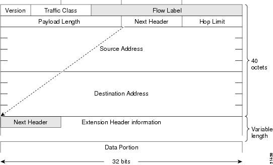
The table below lists the fields in the basic IPv6 packet header.
| Table 2 | Basic IPv6 Packet Header Fields |
| Field |
Description |
|---|---|
| Version |
Similar to the Version field in the IPv4 packet header, except that the field lists number 6 for IPv6 instead of number 4 for IPv4. |
| Traffic Class |
Similar to the Type of Service field in the IPv4 packet header. The Traffic Class field tags packets with a traffic class that is used in differentiated services. |
| Flow Label |
A new field in the IPv6 packet header. The Flow Label field tags packets with a specific flow that differentiates the packets at the network layer. |
| Payload Length |
Similar to the Total Length field in the IPv4 packet header. The Payload Length field indicates the total length of the data portion of the packet. |
| Next Header |
Similar to the Protocol field in the IPv4 packet header. The value of the Next Header field determines the type of information following the basic IPv6 header. The type of information following the basic IPv6 header can be a transport-layer packet, for example, a TCP or UDP packet, or an Extension Header, as shown in the figure immediately above. |
| Hop Limit |
Similar to the Time to Live field in the IPv4 packet header. The value of the Hop Limit field specifies the maximum number of devices that an IPv6 packet can pass through before the packet is considered invalid. Each device decrements the value by one. Because no checksum is in the IPv6 header, the device can decrement the value without needing to recalculate the checksum, which saves processing resources. |
| Source Address |
Similar to the Source Address field in the IPv4 packet header, except that the field contains a 128-bit source address for IPv6 instead of a 32-bit source address for IPv4. |
| Destination Address |
Similar to the Destination Address field in the IPv4 packet header, except that the field contains a 128-bit destination address for IPv6 instead of a 32-bit destination address for IPv4. |
Following the eight fields of the basic IPv6 packet header are optional extension headers and the data portion of the packet. If present, each extension header is aligned to 64 bits. There is no fixed number of extension headers in an IPv6 packet. The extension headers form a chain of headers. Each extension header is identified by the Next Header field of the previous header. Typically, the final extension header has a Next Header field of a transport-layer protocol, such as TCP or UDP. The figure below shows the IPv6 extension header format.
| Figure 3 | IPv6 Extension Header Format |
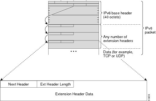
The table below lists the extension header types and their Next Header field values.
| Table 3 | IPv6 Extension Header Types |
| Header Type |
Next Header Value |
Description |
|---|---|---|
| Hop-by-hop options header |
0 |
This header is processed by all hops in the path of a packet. When present, the hop-by-hop options header always follows immediately after the basic IPv6 packet header. |
| Destination options header |
60 |
The destination options header can follow any hop-by-hop options header, in which case the destination options header is processed at the final destination and also at each visited address specified by a routing header. Alternatively, the destination options header can follow any Encapsulating Security Payload (ESP) header, in which case the destination options header is processed only at the final destination. |
| Routing header |
43 |
The routing header is used for source routing. |
| Fragment header |
44 |
The fragment header is used when a source must fragment a packet that is larger than the maximum transmission unit (MTU) for the path between itself and a destination. The Fragment header is used in each fragmented packet. |
| Authentication header and ESP header |
51
50 |
The Authentication header and the ESP header are used within IP Security Protocol (IPsec) to provide authentication, integrity, and confidentiality of a packet. These headers are identical for both IPv4 and IPv6. |
| Upper-layer headers |
6 (TCP) 17 (UDP) |
The upper-layer (transport) headers are the typical headers used inside a packet to transport the data. The two main transport protocols are TCP and UDP. |
| Mobility headers |
135 |
Extension headers used by mobile nodes, correspondent nodes, and home agents in all messaging related to the creation and management of bindings. |
DNS for IPv6
IPv6 supports DNS record types that are supported in the DNS name-to-address and address-to-name lookup processes. The DNS record types support IPv6 addresses. IPv6 also supports the reverse mapping of IPv6 addresses to DNS names.
A name server is used to track information associated with domain names. A name server can maintain a database of hostname-to-address mappings. Each name can map to one or more IPv4 addresses, IPv6 addresses, or both address types. In order to use this service to map domain names to IPv6 addresses, you must specify a name server and enable the DNS.
Cisco software maintains a cache of hostname-to-address mappings for use by the connect, telnet, and ping commands, related Telnet support operations, and many other commands that generate command output. This cache speeds the conversion of names to addresses.
Similar to IPv4, IPv6 uses a naming scheme that allows a network device to be identified by its location within a hierarchical name space that provides for domains. Domain names are joined with periods (.) as the delimiting characters. For example, Cisco is a commercial organization that is identified by a com domain name, so its domain name is cisco.com. A specific device in this domain, the FTP server, for example, is identified as ftp.cisco.com.
The following table lists the IPv6 DNS record types.
| Table 4 | IPv6 DNS Record Types |
Cisco Discovery Protocol IPv6 Address Support
The Cisco Discovery Protocol IPv6 address support for neighbor information feature adds the ability to transfer IPv6 addressing information between two Cisco devices. Cisco Discovery Protocol support for IPv6 addresses provides IPv6 information to network management products and troubleshooting tools.
IPv6 Prefix Aggregation
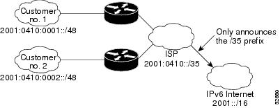
The aggregatable nature of the IPv6 address space enables an IPv6 addressing hierarchy. For example, an enterprise can subdivide a single IPv6 prefix from a service provider into multiple, longer prefixes for use within its internal network. Conversely, a service provider can aggregate all of the prefixes of its customers into a single, shorter prefix that the service provider can then advertise over the IPv6 internet (see the figure below).
| Figure 4 | IPv6 Prefix Aggregation |
IPv6 Site Multihoming
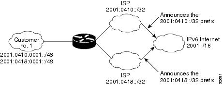
Multiple IPv6 prefixes can be assigned to networks and hosts. Having multiple prefixes assigned to a network allows that network to connect easily to multiple ISPs without breaking the global routing table (see the figure below).
| Figure 5 | IPv6 Site Multihoming |
IPv6 Data Links
In IPv6 networks, a data link is a network sharing a particular link-local prefix. Data links are networks arbitrarily segmented by a network administrator in order to provide a multilevel, hierarchical routing structure while shielding the subnetwork from the addressing complexity of attached networks. The function of a subnetwork in IPv6 is similar to a subnetwork in IPv4. A subnetwork prefix is associated with one data link; multiple subnetwork prefixes may be assigned to the same data link.
The following data links are supported for IPv6: ATM permanent virtual circuit (PVC) and ATM LANE, dynamic packet transport (DPT), Ethernet, Fast Ethernet, FDDI, Frame Relay PVC, Gigabit Ethernet, Cisco High-Level Data Link Control (HDLC), ISDN, PPP over Packet over SONET (PoS), and serial interfaces.
IPv6 for Cisco Software Support for Wide-Area Networking Technologies
IPv6 for Cisco software supports wide-area networking technologies such as ATM PVCs, Frame Relay PVCs, Cisco HDLC, ISDN, PoS, and serial (synchronous and asynchronous) interface types. These technologies function the same in IPv6 as they do in IPv4.
IPv6 Addresses and PVCs
Broadcast and multicast are used in LANs to map protocol (network layer) addresses to the hardware addresses of remote nodes (hosts and devices). Because using broadcast and multicast to map network layer addresses to hardware addresses in circuit-based WANs such as ATM and Frame Relay networks is difficult to implement, these networks use implicit, explicit, and dynamic mappings for the network layer addresses of remote nodes and the PVCs used to reach the addresses.
Assigning an IPv6 address to an interface by using the ipv6 address command defines the IPv6 addresses for the interface and the network that is directly connected to the interface. If only one PVC is terminated on the interface (the interface is a point-to-point interface), there is an implicit mapping between all of the IPv6 addresses on the network and the PVC used to reach the addresses (no additional address mappings are needed). If several PVCs are terminated on the interface (the interface is a point-to-multipoint interface), the protocol ipv6 command (for ATM networks) or the frame-relay map ipv6 command (for Frame Relay networks) is used to configure explicit mappings between the IPv6 addresses of the remote nodes and the PVCs used to reach the addresses.
 Note |
Given that IPv6 supports multiple address types, and depending on which applications or protocols are configured on a point-to-multipoint interface, you may need to configure multiple explicit mappings between the IPv6 addresses of the interface and the PVC used to reach the addresses. For example, explicitly mapping both the link-local and global IPv6 address of a point-to-multipoint interface to the PVC on which the interface terminates ensures that the Interior Gateway Protocol (IGP) configured on the interface forwards traffic to and from the PVC correctly. |
Routed Bridge Encapsulation for IPv6
Routed bridge encapsulation (RBE) provides a mechanism for routing a protocol from a bridged interface to another routed or bridged interface. RBE for IPv6 can be used on ATM point-to-point subinterfaces that are configured for IPv6 half-bridging. Routing of IP packets and IPv6 half-bridging, bridging, PPP over Ethernet (PPPoE), or other Ethernet 802.3-encapsulated protocols can be configured on the same subinterface.
IPv6 Redirect Messages
The IPv6 Redirect Messages feature enables a device to send ICMP IPv6 neighbor redirect messages to inform hosts of better first hop nodes (devices or hosts) on the path to a destination.
IPv6 on BVI Interfaces for Bridging and Routing
Integrated routing and bridging (IRB) enables users to route a given protocol between routed interfaces and bridge groups or route a given protocol between bridge groups. Specifically, local or unroutable traffic will be bridged among the bridged interfaces in the same bridge group, while routable traffic will be routed to other routed interfaces or bridge groups. If you want both bridging and routing capabilities, IRB is required. If you want only bridging, you must disable routing. To disable the routing function for IPv6, you must configure the no ipv6 unicast-routing command.
IPv6 is supported in the bridge virtual interface (BVI), which is the IPv4 interface for bridged interfaces. Because bridging is in the data link layer and routing is in the network layer, they have different protocol configuration models to follow. In the basic IPv4 model, for example, all bridged interfaces should belong to the same network, while each routed interface represents a distinct network. Routed traffic is destined for the device, while bridged traffic is never destined for the device. Using BVI avoids the confusion of which protocol configuration model to use when both bridging and routing a given protocol in the same bridge group.
 Note |
BVIs in IPv6 are not supported with Network Address Translation--Protocol Translation (NAT-PT). |
Dual IPv4 and IPv6 Protocol Stacks
The dual IPv4 and IPv6 protocol stack technique can be used to transition to IPv6. It enables gradual, one-by-one upgrades to applications running on nodes. Applications running on nodes are upgraded to make use of the IPv6 protocol stack. Applications that are not upgraded (for example, they support only the IPv4 protocol stack) can coexist with upgraded applications on a node. New and upgraded applications make use of both the IPv4 and IPv6 protocol stacks (see the figure below).
| Figure 6 | Dual IPv4 and IPv6 Protocol Stack Technique |
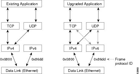
One application program interface (API) supports both IPv4 and IPv6 addresses and DNS requests. An application can be upgraded to the new API and still use only the IPv4 protocol stack. The Cisco software supports the dual IPv4 and IPv6 protocol stack technique. When an interface is configured with both an IPv4 and an IPv6 address, the interface will forward both IPv4 and IPv6 traffic.
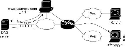
In the figure below, an application that supports dual IPv4 and IPv6 protocol stacks requests all available addresses for the destination hostname www.example.com from a DNS server. The DNS server replies with all available addresses (both IPv4 and IPv6 addresses) for www.example.com. The application chooses an address (in most cases, IPv6 addresses are the default choice), and connects the source node to the destination using the IPv6 protocol stack.
| Figure 7 | Dual IPv4 and IPv6 Protocol Stack Applications |
How to Configure IPv6 Addressing and Basic Connectivity
- Configuring IPv6 Addressing and Enabling IPv6 Routing
- Configuring an Interface to Support the IPv4 and IPv6 Protocol Stacks
- Mapping Hostnames to IPv6 Addresses
- Displaying IPv6 Redirect Messages
Configuring IPv6 Addressing and Enabling IPv6 Routing
DETAILED STEPS
| Command or Action | Purpose | |
|---|---|---|
|
|
Example: Device> enable |
Enables privileged EXEC mode. |
|
|
Example: Device# configure terminal |
Enters global configuration mode. |
|
|
Example: Device(config)# interface ethernet 0/0 |
Specifies an interface type and number, and places the device in interface configuration mode. |
|
|
Example: Device(config-if)# ipv6 address 2001:DB8:0:1::/64 eui-64 Example: Device(config-if)# ipv6 address FE80::260:3EFF:FE11:6770 link-local Example: Device(config-if) ipv6 address 2001:DB8:1:1:FFFF:FFFF:FFFF:FFFE/64 anycast Example: Device(config-if)# ipv6 enable |
Specifies an IPv6 network assigned to the interface and enables IPv6 processing on the interface. or Specifies an IPv6 address assigned to the interface and enables IPv6 processing on the interface. or Automatically configures an IPv6 link-local address on the interface while also enabling the interface for IPv6 processing. or Enable IPv6 processing on an interface that has not been configured with an explicit IPv6 address.
|
|
|
Example: Device(config-if)# exit |
Exits interface configuration mode, and returns the device to global configuration mode. |
|
|
Example: Device(config)# ipv6 unicast-routing |
Enables the forwarding of IPv6 unicast datagrams. |
Configuring an Interface to Support the IPv4 and IPv6 Protocol Stacks
When an interface in a Cisco networking device is configured with both an IPv4 and an IPv6 address, the interface forwards both IPv4 and IPv6 traffic; that is, the interface can send and receive data on both IPv4 and IPv6 networks.
DETAILED STEPS
| Command or Action | Purpose | |
|---|---|---|
|
|
Example: Device> enable |
Enables privileged EXEC mode. |
|
|
Example: Device# configure terminal |
Enters global configuration mode. |
|
|
Example: Device(config)# ipv6 unicast-routing |
Enables the forwarding of IPv6 unicast datagrams. |
|
|
Example: Device(config)# interface ethernet 0 |
Specifies the interface type and number, and enters interface configuration mode. |
|
|
Example: Device(config-if)# ip address 192.168.99.1 255.255.255.0 |
Specifies a primary or secondary IPv4 address for an interface. |
|
|
Example: Device(config-if)# ipv6 address 2001:DB8:c18:1::3/64 |
Specifies the IPv6 network assigned to the interface and enables IPv6 processing on the interface. |
Mapping Hostnames to IPv6 Addresses
DETAILED STEPS
| Command or Action | Purpose | |||
|---|---|---|---|---|
|
|
Example: Device> enable |
Enables privileged EXEC mode. |
||
|
|
Example: Device# configure terminal |
Enters global configuration mode. |
||
|
|
Example: Device(config)# ipv6 host cisco-sj 2001:DB8:20:1::12 |
Defines a static hostname-to-address mapping in the hostname cache.
|
||
|
|
Example: Device(config)# ip domain-name cisco.com Example: Device(config)# ip domain list cisco1.com |
(Optional) Defines a default domain name that the Cisco software will use to complete unqualified hostnames. or (Optional) Defines a list of default domain names to complete unqualified hostnames.
|
||
|
|
Example: Device(config)# ip name-server 2001:DB8::250:8bff:fee8:f800 2001:DB8:0:f004::1 |
Specifies one or more hosts that supply name information.
|
||
|
|
Example: Device(config)# ip domain-lookup |
Enables DNS-based address translation. |
Displaying IPv6 Redirect Messages
DETAILED STEPS
| Command or Action | Purpose | |
|---|---|---|
|
|
Example: Device# enable |
Enables privileged EXEC mode. |
|
|
Example: Device# show ipv6 interface ethernet 0 |
Displays the usability status of interfaces configured for IPv6. |
|
|
Example: Device# show ipv6 neighbors ethernet 2 |
Displays IPv6 neighbor discovery cache information. |
|
|
Example: Device# show ipv6 route |
Displays the current contents of the IPv6 routing table. |
|
|
Example: Device# show ipv6 traffic |
Displays statistics about IPv6 traffic. |
|
|
Example: Device# show atm map |
Displays the list of all configured ATM static maps to remote hosts on an ATM network and on ATM bundle maps. |
|
|
Example: Device# show hosts |
Displays the default domain name, the style of name lookup service, a list of name server hosts, and the cached list of hostnames and addresses. |
|
|
Example: Device# show running-config |
Displays the current configuration running on the device. |
Configuration Examples for IPv6 Addressing and Basic Connectivity
- Example: IPv6 Addressing and IPv6 Routing Configuration
- Example: Dual-Protocol Stack Configuration
- Example: Hostname-to-Address Mappings Configuration
Example: IPv6 Addressing and IPv6 Routing Configuration
In this example, IPv6 is enabled on the device with both a link-local address and a global address based on the IPv6 prefix 2001:DB8:c18:1::/64. The EUI-64 interface ID is used in the low-order 64 bits of both addresses. Output from the show ipv6 interface command is included to show how the interface ID (260:3EFF:FE47:1530) is appended to the link-local prefix FE80::/64 of Ethernet interface 0.
ipv6 unicast-routing
interface ethernet 0
  ipv6 address 2001:DB8:c18:1::/64 eui-64

Device# show ipv6 interface ethernet 0

Ethernet0 is up, line protocol is up
 IPv6 is enabled, link-local address is FE80::260:3EFF:FE47:1530
  Global unicast address(es):
    2001:DB8:C18:1:260:3EFF:FE47:1530, subnet is 2001:DB8:C18:1::/64
  Joined group address(es):
    FF02::1
    FF02::2
    FF02::1:FF47:1530
    FF02::9
  MTU is 1500 bytes
  ICMP error messages limited to one every 500 milliseconds
  ND reachable time is 30000 milliseconds
  ND advertised reachable time is 0 milliseconds
  ND advertised retransmit interval is 0 milliseconds
  ND router advertisements are sent every 200 seconds
  ND router advertisements live for 1800 seconds
  Hosts use stateless autoconfig for addresses.
In the following example, multiple IPv6 global addresses within the prefix 2001:DB8::/64 are configured on Ethernet interface 0:
interface ethernet 0
 ipv6 address 2001:DB8::1/64
 ipv6 address 2001:DB8::/64 eui-64
Example: Dual-Protocol Stack Configuration
This example shows how to enable the forwarding of IPv6 unicast datagrams globally on the device and configures Ethernet interface 0 with both an IPv4 address and an IPv6 address:
ipv6 unicast-routing
interface Ethernet 0
  ip address 192.168.99.1 255.255.255.0
  ipv6 address 2001:DB8:c18:1::3/64
Example: Hostname-to-Address Mappings Configuration
The following example defines two static hostname-to-address mappings in the hostname cache, establishes a domain list with several alternate domain names to complete unqualified hostnames, specifies host 2001:DB8::250:8bff:fee8:f800 and host 2001:DB8:0:f004::1 as the name servers, and reenables the DNS service:
ipv6 host cisco-sj 2001:DB8:700:20:1::12
ipv6 host cisco-hq 2001:DB8:768::1 2001:DB8:20:1::22
ip domain list domain1-list.com
ip domain list serviceprovider2-name.com
ip domain list college2-name.edu
ip name-server 2001:DB8::250:8bff:fee8:f800 2001:DB8:0:f004::1
ip domain-lookup
Additional References
Related Documents
| Related Topic | Document Title |
|---|---|
| IPv6 addressing and connectivity |
IPv6 Configuration Guide |
| IPv4 addressing |
IP Addressing: IPv4 Addressing Configuration Guide |
| IPv4 services configuration |
IP Application Services Configuration Guide |
| Cisco IOS commands |
|
| IPv6 commands |
Cisco IOS IPv6 Command Reference |
| Cisco IOS IPv6 features |
Cisco IOS IPv6 Feature Mapping |
Standards and RFCs
| Standard/RFC | Title |
|---|---|
| RFCs for IPv6 |
IPv6 RFCs |
MIBs
| MIB |
MIBs Link |
|---|---|
| No new or modified MIBs are supported by this feature, and support for existing MIBs has not been modified by this feature. |
To locate and download MIBs for selected platforms, Cisco IOS releases, and feature sets, use Cisco MIB Locator found at the following URL: |
Technical Assistance
| Description | Link |
|---|---|
| The Cisco Support and Documentation website provides online resources to download documentation, software, and tools. Use these resources to install and configure the software and to troubleshoot and resolve technical issues with Cisco products and technologies. Access to most tools on the Cisco Support and Documentation website requires a Cisco.com user ID and password. |
Feature Information for IPv6 Addressing and Basic Connectivity
The following table provides release information about the feature or features described in this module. This table lists only the software release that introduced support for a given feature in a given software release train. Unless noted otherwise, subsequent releases of that software release train also support that feature.
Use Cisco Feature Navigator to find information about platform support and Cisco software image support. To access Cisco Feature Navigator, go to www.cisco.com/go/cfn. An account on Cisco.com is not required.
| Table 5 | Feature Information for IPv6 Addressing and Basic Connectivity |
| Feature Name | Releases | Feature Information |
|---|---|---|
| Internet Protocol version 6 (IPv6) |
12.0(22)S 12.2(2)T 12.2(14)S 12.2(17a)SX1 12.2(25)SEA 12.2(28)SB 12.2(33)SRA Cisco IOS XE Release 2.1 |
IPv6 expands the number of network address bits from 32 bits to 128 bits, which provides more than enough globally unique IP addresses for every networked device on the planet. The following commands were introduced or modified: ip address, ip domain list, ip domain-lookup ip domain name, ip name-server, ipv6 address, ipv6 address anycast, ipv6 address eui-64, ipv6 address link-local, ipv6 enable, ipv6 host, ipv6 unicast-routing. |
| IPv6 Data Link: VLANs using Cisco Inter-Switch Link |
12.2(2)T 12.2(18)SXE 12.2(25)SEA 12.2(25)SG 12.2(33)SRA 15.0(2)SG 3.2.0SG |
IPv6 supports this feature. No commands were introduced or modified. |
| IPv6 Data Link: VLANs Using IEEE 802.1Q Encapsulation |
12.2(2)T 12.2(18)SXE 12.2(25)SEA 12.2(25)SG 12.2(33)SRA 15.0(2)SG 3.2.0SG |
IPv6 supports this feature. No commands were introduced or modified. |
| IPv6 Services: Cisco Discovery Protocol--IPv6 Address Family Support for Neighbor Information |
12.2(8)T 12.2(14)S 12.2(18)SXE 12.2(25)SEE 12.2(25)SG 12.2(33)SRA Cisco IOS XE Release 2.1 |
The Cisco Discovery Protocol--IPv6 Address Support for Neighbor Information feature adds the ability to transfer IPv6 addressing information between two Cisco devices. No commands were introduced or modified. |
Cisco and the Cisco logo are trademarks or registered trademarks of Cisco and/or its affiliates in the U.S. and other countries. To view a list of Cisco trademarks, go to this URL: www.cisco.com/go/trademarks. Third-party trademarks mentioned are the property of their respective owners. The use of the word partner does not imply a partnership relationship between Cisco and any other company. (1110R)
Any Internet Protocol (IP) addresses and phone numbers used in this document are not intended to be actual addresses and phone numbers. Any examples, command display output, network topology diagrams, and other figures included in the document are shown for illustrative purposes only. Any use of actual IP addresses or phone numbers in illustrative content is unintentional and coincidental.
 Feedback