Prerequisites for Configuring ITU-T G.8032 Ethernet Ring Protection Switching
-
The Ethernet Flow Points (EFPs) and Trunk Ethernet Flow Points (TEFPs) must be configured.
The documentation set for this product strives to use bias-free language. For the purposes of this documentation set, bias-free is defined as language that does not imply discrimination based on age, disability, gender, racial identity, ethnic identity, sexual orientation, socioeconomic status, and intersectionality. Exceptions may be present in the documentation due to language that is hardcoded in the user interfaces of the product software, language used based on RFP documentation, or language that is used by a referenced third-party product. Learn more about how Cisco is using Inclusive Language.
The ITU-T G.8032 Ethernet Ring Protection Switching feature implements protection switching mechanisms for Ethernet layer ring topologies. This feature uses the G.8032 Ethernet Ring Protection (ERP) protocol, defined in ITU-T G.8032, to provide protection for Ethernet traffic in a ring topology, while ensuring that no loops are within the ring at the Ethernet layer. The loops are prevented by blocking traffic on either a predetermined link or a failed link.
The Ethernet Flow Points (EFPs) and Trunk Ethernet Flow Points (TEFPs) must be configured.
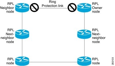
An Ethernet ring consists of multiple Ethernet ring nodes. Each Ethernet ring node is connected to adjacent Ethernet ring nodes using two independent ring links. A ring link prohibits formation of loops that affect the network. The Ethernet ring uses a specific link to protect the entire Ethernet ring. This specific link is called the Ring Protection Link (RPL). A ring link is bound by two adjacent Ethernet ring nodes and a port for a ring link (also known as a ring port). There must be at least two Ethernet ring nodes in an Ethernet ring.
The Ethernet ring protection functionality includes the following:
Loop avoidance
The use of learning, forwarding, and Filtering Database (FDB) mechanisms
Loop avoidance in an Ethernet ring is achieved by ensuring that, at any time, traffic flows on all but the Ring Protection Link (RPL).
The following is a list of RPL types (or RPL nodes) and their functions:
RPL owner—Responsible for blocking traffic over the RPL so that no loops are formed in the Ethernet traffic. There can be only one RPL owner in a ring.
RPL neighbor node—An Ethernet ring node adjacent to the RPL. It is responsible for blocking its end of the RPL under normal conditions. This node type is optional and prevents RPL usage when protected.
RPL next-neighbor node—Next-neighbor node is an Ethernet ring node adjacent to an RPL owner node or RPL neighbor node. It is mainly used for FDB flush optimization on the ring. This node is also optional.
The following figure illustrates the G.8032 Ethernet ring topology.
Nodes on the ring use control messages called Ring Automatic Protection Switching (R-APS) messages to coordinate the activities of switching the ring protection link (RPL) on and off. Any failure along the ring triggers a R-APS Signal Failure (R-APS SF) message in both directions of the nodes adjacent to the failed link, after the nodes have blocked the port facing the failed link. On obtaining this message, the RPL owner unblocks the RPL port.
 Note |
A single link failure in the ring ensures a loop-free topology. |
Connectivity Fault Management (CFM) and line status messages are used to detect ring link and node failure. During the recovery phase, when the failed link is restored, the nodes adjacent to the restored link send Ring Automatic Protection Switching (R-APS) No Request (R-APS NR) messages. On obtaining this message, the ring protection link (RPL) owner blocks the RPL port and sends R-APS NR and R-APS RPL (R-APS NR, RB) messages. These messages cause all other nodes, other than the RPL owner in the ring, to unblock all blocked ports. The Ethernet Ring Protection (ERP) protocol works for both unidirectional failure and multiple link failure scenarios in a ring topology.
Note |
The G.8032 Ethernet Ring Protection (ERP) protocol uses CFM Continuity Check Messages (CCMs) at an interval of 3.3 milliseconds (ms). At this interval (which is supported only on selected platforms), SONET-like switching time performance and loop-free traffic can be achieved. |
A G.8032 ring supports these basic operator administrative commands:
Force switch (FS)—Allows the operator to forcefully block a particular ring port. Note the following points about Force Switch commands:
Effective even if there is an existing SF condition
Multiple FS commands for ring are supported
May be used to allow immediate maintenance operations
Manual switch (MS)—Allows the operator to manually block a particular ring port. Note the following points about MS commands:
Ineffective in an existing FS or signal failure (SF) condition
Overridden by new FS or SF conditions
When multiple MS commands are executed more than once on the same device, all MS commands are cancelled.
When multiple MS commands are executed on different devices in the ring, for the same instance, then the command executed on the second device is rejected.
Clear—Cancels an existing FS or MS command on the ring port. The Clear command is used at the ring protection link (RPL) owner to clear a nonrevertive mode condition.
A G.8032 ring can support multiple instances. An instance is a logical ring running over a physical ring. Such instances are used for various reasons, such as load-balancing VLANs over a ring. For example, odd-numbered VLANs may go in one direction of the ring, and even-numbered VLANs may go in the other direction. Specific VLANs can be configured under only one instance. They cannot overlap multiple instances. Otherwise, data traffic or Ring Automatic Protection Switching (R-APS) messages may cross logical rings, which is not desirable.
Note |
G.8032 Ethernet Ring Protection Switching Version 1 and Version 2 are supported. |
The G.8032 Ethernet Ring Protection (ERP) protocol specifies the use of different timers to avoid race conditions and unnecessary switching operations:
After a signal failure (SF) condition, a Wait-to-Restore (WTR) timer is used to verify that the SF is not intermittent.
The WTR timer can be configured by the operator. The default time interval is 5 minutes; the time interval ranges from 1 to 12 minutes.
Note |
The WTB timer interval may be shorter than the WTR timer interval. |
Guard timer—Used by all nodes when changing state; the guard timer blocks latent outdated messages from causing unnecessary state changes. The guard timer can be configured. The default time interval is 500 ms; the time interval ranges from 10 to 2000 ms.
The recommended Guard Timer is 500 ms.
Hold-off timers—Used by the underlying Ethernet layer to filter out intermittent link faults. The hold-off timer can be configured. The default time interval is 0 seconds; the time interval ranges from 0 to 10 seconds. Faults are reported to the ring protection mechanism only if this timer expires.
The following figure illustrates protection switching functionality in a single-link failure.
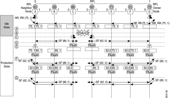

The figure represents an Ethernet ring topology consisting of seven Ethernet ring nodes. The ring protection link (RPL) is the ring link between Ethernet ring nodes A and G. In this topology, both ends of the RPL are blocked. Ethernet ring node G is the RPL owner node, and Ethernet ring node A is the RPL neighbor node.
The following sequence describes the steps followed in the single-link failure:
A link operates in the normal condition.
A failure occurs.
Ethernet ring nodes C and D detect a local signal failure (SF) condition and after the hold-off time interval, block the failed ring port and perform the FDB flush.
Ethernet ring nodes C and D start sending Ring Automatic Protection Switching (R-APS) SF messages periodically along with the (node ID and bidirectional path-protected ring (BPR) identifier pair) on both ring ports while the SF condition persists.
All Ethernet ring nodes receiving an R-APS SF message perform the FDB flush. When the RPL owner node G and RPL neighbor node A receive an R-APS SF message, the Ethernet ring node unblocks its end of the RPL and performs the FDB flush.
All Ethernet ring nodes receiving a second R-APS SF message perform the FDB flush again; the additional FDB flush is because of the node ID and BPR-based configuration.
R-APS SF messages are detected on the Ethernet Ring indicating a stable SF condition. Further R-APS SF messages trigger no further action.
The following figure illustrates the steps taken in a revertive operation in a single-link failure.
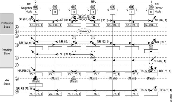
The following sequence describes the steps followed in the single-link failure revertive (recovery) operation:
A link operates in the stable SF condition.
Recovery of link failure occurs.
Ethernet ring nodes C and D detect clearing of the SF condition, start the guard timer, and initiate periodic transmission of the R-APS No Request (NR) messages on both ring ports. (The guard timer prevents the reception of R-APS messages.)
When the Ethernet ring nodes receive an R-APS NR message, the node ID and BPR identifier pair of a receiving ring port is deleted and the RPL owner node starts the Wait-to-Restore (WTR) timer.
When the guard timer expires on Ethernet ring nodes C and D, the nodes may accept the new R-APS messages, if any. Ethernet ring node D receives an R-APS NR message with a higher node ID from Ethernet ring node C, and unblocks its nonfailed ring port.
When the WTR timer expires, the RPL owner node blocks its end of the RPL, sends R-APS (NR or route blocked [RB]) message with the (node ID and BPR identifier pair), and performs the FDB flush.
When Ethernet ring node C receives an R-APS (NR or RB) message, the node removes the block on its blocked ring ports, and stops sending R-APS NR messages. On the other hand, when the RPL neighbor node A receives an R-APS NR or RB message, the node blocks its end of the RPL. In addition, Ethernet ring nodes A to F perform the FDB flush when receiving an RAPS NR or RB message because of the node ID and BPR-based configuration.
An Ethernet flow point (EFP) is a forwarding decision point in the provider edge (PE) router, which gives network designers flexibility to make many Layer 2 flow decisions within the interface. Many EFPs can be configured on a single physical port. (The number varies from one device to another.) EFPs are the logical demarcation points of an Ethernet virtual connection (EVC) on an interface. An EVC that uses two or more user network interfaces (UNIs) requires an EFP on the associated ingress and egress interfaces of every device that the EVC passes through.
EFPs can be configured on any Layer 2 traffic port; however, they are usually configured on UNI ports. The following parameters (matching criteria) can be configured on the EFP:
Frames of a specific VLAN, a VLAN range, or a list of VLANs (100-150 or 100,103,110)
Frames with no tags (untagged)
Frames with identical double-tags (VLAN tags) as specified
Frames with identical Class of Service (CoS) values
A frame passes each configured match criterion until the correct matching point is found. If a frame does not fit any of the matching criteria, it is dropped. Default criteria can be configured to avoid dropping frames.
You can configure a new type of TEFP called TEFP with encapsulation from bridge domain (BD). All the BDs configured on the switch are part of the VLAN list of the encapsulated TEFP. The TEFP is encapsulated using the encapsulation dot1q from-bd command. The feature brings about the following interaction between the Ethernet-EFP and Layer2-bridge domain components:
If BDs exist in the system and a TEFP with encapsulation from bridge domain is created, then all the BDs get added to the VLAN list of TEFP with encapsulation from bridge domain.
If TEFP with encapsulation from bridge domain exists in the system and a new BD is created, then the BD is added to the VLAN list of all the TEFP with encapsulation from bridge domain in the system.
If TEFP with encapsulation from bridge domain exists in the system and a BD gets deleted, and if the deleted BD is not part of an existing TEFP or EFP then it gets deleted from all the TEFP with encapsulation from bridge domain in the system.
The following types of commands can be used in an EFP:
Rewrite commands—In each EFP, VLAN tag management can be specified with the following actions:
Pop—1) pops out a tag; 2) pops out two tags
Push— pushes in a tag
Translate—1 to 1) changes a tag value; 1 to 2) pops one tag and pushes two tags; 2 to 1) pops two tags and pushes one tag; 2 to 2) changes the value for two tags
Forwarding commands—Each EFP specifies the forwarding command for the frames that enter the EFP. Only one forwarding command can be configured per EFP. The forwarding options are as follows:
Layer 2 point-to-point forwarding to a pseudowire tunnel
Multipoint bridge forwarding to a bridge domain entity
Local switch-to-switch forwarding between two different interfaces
Feature commands—In each EFP, the QoS features or parameters can be changed and the ACL can be updated.
Configuring a service instance on a Layer 2 port creates a pseudoport or EFP on which you configure EVC features. Each service instance has a unique number per interface, but you can use the same number on different interfaces because service instances on different ports are not related.
An EFP classifies frames from the same physical port to one of the multiple service instances associated with that port, based on user-defined criteria. Each EFP can be associated with different forwarding actions and behavior.
When an EFP is created, the initial state is UP. The state changes to DOWN under the following circumstances:
The EFP is explicitly shut down by a user.
The main interface to which the EFP is associated is down or removed.
If the EFP belongs to a bridge domain, the bridge domain is down.
The EFP is forced down as an error-prevention measure of certain features.
Use the service instance ethernet interface configuration command to create an EFP on a Layer 2 interface and to enter service instance configuration mode. Service instance configuration mode is used to configure all management and control data plane attributes and parameters that apply to the service instance on a per-interface basis. The service instance number is the EFP identifier.
After the device enters service instance configuration mode, you can configure these options:
default--Sets a command to its defaults
description--Adds a service instance-specific description
encapsulation--Configures Ethernet frame match criteria
exit--Exits from service instance configuration mode
no--Negates a command or sets its defaults
shutdown--Takes the service instance out of service
|
Feature Name |
Release Information |
Feature Description |
|---|---|---|
|
G.8032 Support for IEEE 802.1Q EFPs |
Cisco IOS XE Bengaluru 17.6.1 |
This feature supports G.8032 Ethernet ring protection for IEEE 802.1Q Ethernet Flow Points (EFPs). Prior to this release, G.8032 Ethernet ring protection for IEEE 802.1Q was supported only for Trunk Ethernet Flow Points (TEFPs). |
Given below are the restrictions for configuring the ITU-T G.8032 Ethernet Ring Protection switching:
Note |
Effective Cisco IOS XE Bengaluru 17.6.1, G.8032 is supported on both EFPs and TEFPs with IEEE 802.1Q on the RSP3 Module. |
G.8032 is supported only on EFP bridge domains on the physical interface and port-channel interface.
Note |
G.8032 is supported only on TEFP on the RSP3 Module. Port-channel is not supported on the RSP3 Module. |
G.8032 is supported only on EFP with dot1q, dot1ad, QinQ, or dot1ad-dot1Q encapsulation type.
Note |
G.8032 is supported only on TEFP with dot1q on the RSP3 Module. |
G.8032 is not supported on cross-connect interface.
G.8032 does not support more than two ERP instances per ring.
Link flap occurs while configuring the inclusion or exclusion VLAN list.
Admin shutdown is highly recommended before making any changes in Connectivity Fault Management (CFM) configuration.
The efd notify command must be used under CFM configuration to notify G.8032 of failures, if any.
BFD IPv4 and IPv6 Single Hop is supported. BFD Echo Mode is not supported.
Modification of APS VLAN will not be effective until you delete and reconfigure the G8032 ring configuration.
The following restrictions are applicable for configuring the ITU-T G.8032 Ethernet Ring Protection protocol over EFPs on RSP3:
Adding a VLAN range on the EFP that participates in the G.8032 ring is not supported.
Like TEFPs, G.8032 is supported only on IEEE 802.1Q EFPs with the rewrite action as pop1 symmetric command.
The ports participating in the G.8032 protocol should not have a TEFP, if G.8032 is configured with IEEE 802.1Q EFP.
Both the ring ports must be shut down while migrating TEFPs to EFPs. This results in a service interruption.
While migrating the TEFPs to EFPs, ensure to remove all data VLANs present in both inclusion and exclusion VLAN lists from the ring ports. Reconfigure all of these VLANs on the ring ports.
While configuring G.8032 over an EFP, the encapsulation VLAN and bridge domain values should be the same within a service instance. Using different values for the encapsulation VLAN and bridge domain is not allowed in a service instance.
To configure the Ethernet ring profile, complete the following steps.
| Command or Action | Purpose | |
|---|---|---|
| Step 1 |
enable Example: |
Enables privileged EXEC mode.
|
| Step 2 |
configure terminal Example: |
Enters global configuration mode. |
| Step 3 |
ethernet ring g8032 profile profile-name Example: |
Creates the Ethernet ring profile and enters Ethernet ring profile configuration mode. |
| Step 4 |
timer {guard seconds | hold-off seconds | wtr minutes } Example: |
Specifies the time interval for the guard, hold-off, and Wait-to-Restore (WTR) timers. |
| Step 5 |
non-revertive Example: |
|
| Step 6 |
end Example: |
Returns to user EXEC mode. |
Configuring Ethernet Connectivity Fault Management (CFM) maintenance endpoints (MEPs) is optional although recommended for fast failure detection and CFM monitoring. When CFM monitoring is configured, note the following points:
Static remote MEP (RMEP) checking should be enabled.
The MEPs should be configured to enable Ethernet fault detection.
To enable Ethernet Fault Detection (EFD) for a service to achieve fast convergence, complete the following steps
Note |
Link protection is not supported on the RSP3 Module. |
| Command or Action | Purpose | |
|---|---|---|
| Step 1 |
enable Example: |
Enables privileged EXEC mode.
|
| Step 2 |
configure terminal Example: |
Enters global configuration mode. |
| Step 3 |
ethernet cfm global Example: |
Enables Ethernet CFM globally. |
| Step 4 |
ethernet cfm domaindomain-name level level-id [direction outward] Example: |
Configures the CFM domain for ODU 1 and enters Ethernet CFM configuration mode. |
| Step 5 |
service {ma-name | ma-num | vlan-id vlan-id | vpn-id vpn-id} [port | vlan vlan-id [direction down]] Example: |
Defines a maintenance association for ODU 1 and enters Ethernet CFM service instance configuration mode. |
| Step 6 |
continuity-check [interval time | loss-threshold threshold | static rmep] Example: |
Enables the transmission of continuity check messages (CCMs). |
| Step 7 |
efd notify g8032 Example: |
Enables CFM to notify registered protocols when a defect is detected or cleared, which matches the current fault alarm priority. |
| Step 8 |
end Example: |
Returns to user EXEC mode. |
To configure the Ethernet Protection Ring (EPR), complete the following steps.
| Command or Action | Purpose | |||
|---|---|---|---|---|
| Step 1 |
enable Example: |
Enables privileged EXEC mode.
|
||
| Step 2 |
configure terminal Example: |
Enters global configuration mode. |
||
| Step 3 |
ethernet ring g8032 ring-name Example: |
Specifies the Ethernet ring and enters Ethernet ring port configuration mode. |
||
| Step 4 |
port0 interface type number Example: |
Connects port0 of the local node of the interface to the Ethernet ring and enters Ethernet ring protection mode. |
||
| Step 5 |
monitor service instance instance-id Example: |
Assigns the Ethernet service instance to monitor the ring port (port0) and detect ring failures. |
||
| Step 6 |
exit Example: |
Exits Ethernet ring port configuration mode. |
||
| Step 7 |
port1 {interface type number | none } Example: |
Connects port1 of the local node of the interface to the Ethernet ring and enters Ethernet ring protection mode. |
||
| Step 8 |
monitor service instance instance-id Example: |
Assigns the Ethernet service instance to monitor the ring port (port1) and detect ring failures.
|
||
| Step 9 |
exit Example: |
Exits Ethernet ring port configuration mode. |
||
| Step 10 |
exclusion-list vlan-ids vlan-id Example: |
Specifies VLANs that are unprotected by the Ethernet ring protection mechanism. |
||
| Step 11 |
open-ring Example: |
Specifies the Ethernet ring as an open ring. By default, each node on the Ethernet ring is closed. You must configure the open-ring command on each node for ITU-T G.8032 Ethernet open ring. |
||
| Step 12 |
instance instance-id Example: |
Configures the Ethernet ring instance and enters Ethernet ring instance configuration mode. |
||
| Step 13 |
description descriptive-name Example: |
Specifies a descriptive name for the Ethernet ring instance. |
||
| Step 14 |
profile profile-name Example: |
Specifies the profile associated with the Ethernet ring instance. |
||
| Step 15 |
rpl {port0 | port1 } {owner | neighbor | next-neighbor } Example: |
Specifies the Ethernet ring port on the local node as the RPL owner, neighbor, or next neighbor. |
||
| Step 16 |
inclusion-list vlan-ids vlan-id Example: |
Specifies VLANs that are protected by the Ethernet ring protection mechanism.
|
||
| Step 17 |
aps-channel Example: |
Enters Ethernet ring instance aps-channel configuration mode. |
||
| Step 18 |
level level-value Example: |
Specifies the Automatic Protection Switching (APS) message level for the node on the Ethernet ring.
|
||
| Step 19 |
port0 service instance instance-id Example: |
Associates APS channel information with port0. |
||
| Step 20 |
port1 service instance {instance-id | none } Example: |
Associates APS channel information with port1. |
||
| Step 21 |
end Example: |
Returns to user EXEC mode. |
To configure topology change notification (TCN) propagation, complete the following steps.
| Command or Action | Purpose | |
|---|---|---|
| Step 1 |
enable Example: |
Enables privileged EXEC mode.
|
| Step 2 |
configure terminal Example: |
Enters global configuration mode. |
| Step 3 |
ethernet tcn-propagation G8032 to {REP | G8032} Example: |
Allows topology change notification (TCN) propagation from a source protocol to a destination protocol.
|
| Step 4 |
end Example: |
Returns to user EXEC mode. |
To configure a service instance, complete the following steps.
| Command or Action | Purpose | |
|---|---|---|
| Step 1 |
enable Example: |
Enables privileged EXEC mode.
|
| Step 2 |
configure terminal Example: |
Enters global configuration mode. |
| Step 3 |
interface type number Example: |
Specifies the interface type and number. |
| Step 4 |
service instance instance-id ethernet [evc-id ] Example: |
Creates a service instance (an instance of an EVC) on an interface and enters service instance configuration mode. |
| Step 5 |
encapsulation dot1q vlan-id [native ] Example: |
Defines the matching criteria to be used in order to map ingress dot1q frames on an interface to the appropriate service instance. |
| Step 6 |
bridge-domain bridge-id [split-horizon [group group-id ]] Example: |
Binds the service instance to a bridge domain instance. |
| Step 7 |
end Example: |
Exits service instance configuration mode. |
To verify the ERP switching configuration, use one or more of the following commands in any order.
Note |
Follow these rules while adding or deleting VLANs from the inclusion list:
Addition or Deletion of VLANs in exclusion list is not supported. |
| Command or Action | Purpose | |
|---|---|---|
| Step 1 |
enable Example: |
Enables privileged EXEC mode.
|
| Step 2 |
show ethernet ring g8032 status [ring-name] [instance [instance-id]] Example: |
Displays a status summary for the ERP instance. |
| Step 3 |
show ethernet ring g8032 brief [ring-name] [instance [instance-id]] Example: |
Displays a brief description of the functional state of the ERP instance. |
| Step 4 |
show ethernet ring g8032 summary Example: |
Displays a summary of the number of ERP instances in each state of the ERP switching process. |
| Step 5 |
show ethernet ring g8032 statistics [ring-name] [instance [instance-id]] Example: |
Displays the number of events and Ring Automatic Protection Switching (R-APS) messages received for an ERP instance. |
| Step 6 |
show ethernet ring g8032 profile [profile-name] Example: |
Displays the settings for one or more ERP profiles. |
| Step 7 |
show ethernet ring g8032 port status interface [type number] Example: |
Displays Ethernet ring port status information for the interface. |
| Step 8 |
show ethernet ring g8032 configuration [ring-name] instance [instance-id] Example: |
Displays the details of the ERP instance configuration manager. |
| Step 9 |
show ethernet ring g8032 trace {ctrl [ring-name instance instance-id] | sm} Example: |
Displays information about ERP traces. |
| Step 10 |
end Example: |
Returns to privileged EXEC mode. |
The following is an example of an Ethernet Ring Protection (ERP) switching configuration:
ethernet ring g8032 profile profile_ABC
 timer wtr 1
 timer guard 100
 timer hold-off  1

ethernet ring g8032 major_ring_ABC
 exclusion-list vlan-ids 1000
 port0 interface  GigabitEthernet 0/0/1
  monitor service instance 103
 port1 interface  GigabitEthernet 0/1/0
  monitor service instance 102
 instance 1
  profile profile_ABC
  rpl port0 owner
  inclusion-list vlan-ids 100
  aps-channel
   port0 service instance 100
   port1 service instance 100
  !
interface GigabitEthernet0/1/0
mtu 9216
 no ip address
 negotiation auto
 service instance trunk 1 ethernet
  encapsulation dot1q 60-61
  rewrite ingress tag pop 1 symmetric
  bridge-domain from-encapsulation

 !
!
ethernet cfm domain G8032 level 4
service 8032_service evc 8032-evc vlan 1001 direction down
  continuity-check
  continuity-check interval 3.3ms
  offload sampling 1000
  efd notify g8032
ethernet ring g8032 profile TEST
timer wtr 1
timer guard 100
ethernet ring g8032 open
open-ring
port0 interface GigabitEthernet0/1/3
  monitor service instance 1001
port1 none
instance 1
  profile TEST
  inclusion-list vlan-ids 2-500,1001
  aps-channel
   port0 service instance 1001
   port1 none
  !
!
instance 2
  profile TEST
  rpl port0 owner
  inclusion-list vlan-ids 1002,1005-2005
  aps-channel
   port0 service instance 1002
   port1 none
  !

interface GigabitEthernet0/1/3
no ip address
load-interval 30
shutdown
negotiation auto
storm-control broadcast level 10.00
storm-control multicast level 10.00
storm-control unicast level 90.00
service instance 1 ethernet
  encapsulation untagged
  l2protocol peer lldp
  bridge-domain 1
!
service instance trunk 10 ethernet
  encapsulation dot1q 2-500,1005-2005
  rewrite ingress tag pop 1 symmetric
  bridge-domain from-encapsulation
!
service instance 1001 ethernet 8032-evc
  encapsulation dot1q 1001
  rewrite ingress tag pop 1 symmetric
  bridge-domain 1001
  cfm mep domain G8032 mpid 20
!
service instance 1002 ethernet 8032-evc-1
  encapsulation dot1q 1002
  rewrite ingress tag pop 1 symmetric
  bridge-domain 1002
!
End
The following is an example of a G.8032 ring configuration over an EFP interface:
ethernet ring g8032 profile ringProfile
 timer wtr 1
ethernet ring g8032 closed
 port0 interface GigabitEthernet0/1/3
  monitor service instance 200
 port1 interface GigabitEthernet0/1/4
  monitor service instance 200
 instance 1
  profile ringProfile
  rpl port0 owner
  inclusion-list vlan-ids 101-102,200
  aps-channel
   port0 service instance 200
   port1 service instance 200
  !
 !
interface GigabitEthernet0/1/4
 no ip address
 negotiation auto
 service instance 101 ethernet
  encapsulation dot1q 101
  rewrite ingress tag pop 1 symmetric
  bridge-domain 101
 !
 service instance 102 ethernet
  encapsulation dot1q 102
  rewrite ingress tag pop 1 symmetric
  bridge-domain 102
 !
 service instance 200 ethernet
  encapsulation dot1q 200
  rewrite ingress tag pop 1 symmetric
  bridge-domain 200
 !
interface GigabitEthernet0/1/3
 no ip address
 negotiation auto
 service instance 101 ethernet
  encapsulation dot1q 101
  rewrite ingress tag pop 1 symmetric
  bridge-domain 101
 !
 service instance 102 ethernet
  encapsulation dot1q 102
  rewrite ingress tag pop 1 symmetric
  bridge-domain 102
 !
 service instance 200 ethernet
  encapsulation dot1q 200
  rewrite ingress tag pop 1 symmetric
  bridge-domain 200
 !
The following is sample output from the show ethernet ring g8032 configuration command. Use this command to verify if the configuration entered is valid and to check for any missing configuration parameters.
Device# show ethernet ring g8032 configuration

ethernet ring ring0
 Port0: GigabitEthernet0/0/0 (Monitor: GigabitEthernet0/0/0)
 Port1: GigabitEthernet0/0/4 (Monitor: GigabitEthernet0/0/4)
 Exclusion-list VLAN IDs: 4001-4050
 Open-ring: no
 Instance 1
  Description:
  Profile:     opp
  RPL:
  Inclusion-list VLAN IDs: 2,10-500
  APS channel
   Level: 7
   Port0: Service Instance 1
   Port1: Service Instance 1
  State: configuration resolved
 Feedback