- Read Me First
- MPLS Enhancements to Interfaces MIB
- MPLS Label Switching Router MIB
- MPLS LSP Ping Traceroute for LDP TE and LSP Ping for VCCV
- MPLS LSP Ping, Traceroute, and AToM VCCV
- MPLS EM - MPLS LSP Multipath Tree Trace
- MPLS Label Distribution Protocol MIB
- MPLS Label Distribution Protocol MIB Version 8 Upgrade
- MPLS VPN--MIB Support
- MPLS VPN SNMP Notifications
- Pseudowire Emulation Edge-to-Edge MIBs
- MPLS Traffic Engineering--Fast Reroute MIB
- MPLS Traffic Engineering MIB
- Point-to-Multipoint MPLS-TE MIB
- MPLS-TP MIB
- Index
- Finding Feature Information
- Prerequisites for Pseudowire Emulation Edge-to-Edge MIBs
- Restrictions for Pseudowire Emulation Edge-to-Edge MIBs
- Information About Pseudowire Emulation Edge-to-Edge MIBs
- The Function of a Pseudowire in the PWE3 MIBs
- PWE3 MIBs Architecture
- Components and Functions of the PWE3 MIBs
- Tables in the PW-MIB
- Tables in the PW-MPLS-MIB
- Tables in the PW-ENET-MIB
- Tables in the PW-FR-MIB
- Tables in the PW-ATM-MIB
- Objects in the PWE3 MIBs
- Scalar Objects in the PWE3 MIBs
- Notifications in the PWE3 MIBs
- Benefits of the PWE3 MIBs
- How to Configure Pseudowire Emulation Edge-to-Edge MIBs
Pseudowire Emulation Edge-to-Edge MIBs
The Pseudowire Emulation Edge-to-Edge MIBs for Ethernet, Frame Relay, and ATM Services feature provides Simple Network Management Protocol (SNMP) support within an Any Transport over Multiprotocol Label Switching (AToM) infrastructure emulating Ethernet, Frame Relay, and ATM services over packet switched networks (PSNs). The Pseudowire Emulation Edge-to-Edge (PWE3) MIBs are the following:
- Finding Feature Information
- Prerequisites for Pseudowire Emulation Edge-to-Edge MIBs
- Restrictions for Pseudowire Emulation Edge-to-Edge MIBs
- Information About Pseudowire Emulation Edge-to-Edge MIBs
- How to Configure Pseudowire Emulation Edge-to-Edge MIBs
- Configuration Examples for the Pseudowire Emulation Edge-to-Edge MIBs
- Additional References
- Feature Information for Pseudowire Emulation Edge-to-Edge MIBs
- Glossary
Finding Feature Information
Your software release may not support all the features documented in this module. For the latest caveats and feature information, see Bug Search Tool and the release notes for your platform and software release. To find information about the features documented in this module, and to see a list of the releases in which each feature is supported, see the feature information table at the end of this module.
Use Cisco Feature Navigator to find information about platform support and Cisco software image support. To access Cisco Feature Navigator, go to www.cisco.com/go/cfn. An account on Cisco.com is not required.
Prerequisites for Pseudowire Emulation Edge-to-Edge MIBs
Restrictions for Pseudowire Emulation Edge-to-Edge MIBs
The PWE3 MIBs are limited to read-only (RO) permission for MIB objects except for the cpwVcUp and cpwVcDown notification enable object, cpwVcUpDownNotifEnable, which has been extended to be writable by the SNMP agent.
The following tables in the PW-MIB are not supported: The following objects in the PW-MPLS-MIB are not supported: The following tables in the PW-ENET-MIB are not supported: The following table in the PW-FR-MIB is not supported: The PW-ATM-MIB does not support a high-capacity cell counter per virtual path (VP) or cells per port.
The PW-ATM-MIB virtual path identifier (VPI)/virtual channel identifier (VCI) value for port mode cell relay is 0.
The PW-ATM-MIB VP cell relay VCI value is 0.
The PW-ATM-MIB VP does not support ATM adaptation layer 5 (AAL5); therefore, all packet counters are invalid.
 Note | This feature is not supported over Ethernet, Frame Relay, and ATM in all releases. For more detailed information, see the "Feature Information for Pseudowire Emulation Edge-to-Edge MIBs for Ethernet Frame Relay and ATM Services" section. |
Information About Pseudowire Emulation Edge-to-Edge MIBs
- The Function of a Pseudowire in the PWE3 MIBs
- PWE3 MIBs Architecture
- Components and Functions of the PWE3 MIBs
- Tables in the PW-MIB
- Tables in the PW-MPLS-MIB
- Tables in the PW-ENET-MIB
- Tables in the PW-FR-MIB
- Tables in the PW-ATM-MIB
- Objects in the PWE3 MIBs
- Scalar Objects in the PWE3 MIBs
- Notifications in the PWE3 MIBs
- Benefits of the PWE3 MIBs
The Function of a Pseudowire in the PWE3 MIBs
A pseudowire is a point-to-point connection between pairs of provider edge (PE) routers (as shown in the figure below). Its primary function is to emulate services like Ethernet over an underlying core MPLS network through encapsulation into a common MPLS format. By encapsulating services into a common MPLS format, a pseudowire allows carriers to converge their services to an MPLS network.

PWE3 MIBs Architecture
The PWE3 MIBs architecture shown in the figure below categorizes three groups of MIBs that, when used together, provide the complete emulated service; the native transport, which carries the service across the core network; and the relationship between the two.
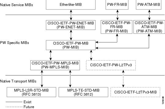
The architecture is modular in that once deployed, new emulated service MIB modules or additional transport MIB modules “plug in” to or extend the existing infrastructure rather than require a new and unique one. This allows you to build management applications without the concern of a new service requiring the deployment of a completely different management strategy. Because the architecture is a generalized association mechanism between existing service and transport MIB modules, native MIB modules work in the absence of the associated PWE3-specific MIBs. The advantage is that if a PWE3-specific MIB has not yet been deployed in Cisco software, which associates a service or transport with pseudowires, these MIB modules can still be queried. However, the only drawback is that the associations with the pseudowires are absent.
Components and Functions of the PWE3 MIBs
The PWE3 MIBs have the following components and functions:
PW-MIB (the pseudowire MIB)
This MIB binds the PW-MPLS-MIB and the PW-ENET-MIB together, and provides status of the pseudowire emulation and statistics and configuration information. The PW-MIB also defines the notifications for pseudowire fault and event monitoring.
PW-MPLS-MIB (the pseudowire MPLS-MIB)
This MIB contains managed objects that can be used by a network manager to monitor pseudowire emulation MPLS services, such as MPLS-traffic engineering (TE)-PSN and MPLS-non-TE-PSN.
This MIB shows the following:
- Cross-connect (XC) indexes for virtual circuits (VCs) that are Label Distribution Protocol (LDP)-signaled and have a preferred path that is not set to an MPLS TE tunnel.
- Tunnel indexes for VCs with a preferred path set to a TE tunnel and an output interface that is a TE tunnel.
PW-ENET-MIB (the pseudowire Ethernet services MIB)
This MIB contains managed objects that can be used by a network manager to monitor pseudowire emulation Ethernet services.
PW-FR-MIB (the pseudowire Frame Relay services MIB)
This MIB contains managed objects that can be used by a network manager to monitor pseudowire emulation Frame Relay services.
This MIB uses a Frame Relay over pseudowire (FRoPW) connection that consists of two segments: the Frame Relay segment and the pseudowire segment. The PW-FR-MIB provides hooks to those segments. The PW MIB contains information about the pseudowire segment, and the PW-FR-MIB contains information about the Frame Relay segment.
The PW-FR-MIB is defined at the Pseudowire Service Emulation Layer and resides on top of the generic PW-MIB as shown in the figure above. Therefore, the PW-FR-MIB is highly dependent on the existence and the service provided by the PW-MIB. In addition, an existing PW-FR connection entry must associate with an existing VC entry in the PW-MIB.
The PW-FR-MIB and the generic PW-MIB are logically tied by the PW VC Index, which is an internal index defined to support the PW-MIB. Each PW VC index uniquely maps into an existing VC entry in the PW-MIB and the PW-FR-MIB.
PW-ATM-MIB (the pseudowire ATM services MIB)
This MIB contains managed objects that can be used by a network manager to monitor pseudowire emulation ATM services.
This MIB uses an ATM over pseudowire (ATMoPW) connection that consists of two segments: the ATM segment and the pseudowire segment. The PW-ATM-MIB provides hooks to those segments. The PW MIB contains information about the pseudowire segment, and the PW-ATM-MIB contains information about the ATM segment called the attachment circuit.
The PW-ATM-MIB is defined at the Pseudowire Service Emulation Layer and resides on top of the generic PW-MIB as shown in the figure above. Therefore, the PW-ATM-MIB is highly dependent on the existence and the service provided by the PW-MIB. In addition, an existing PW-ATM connection entry must associate with an existing VC entry in the PW-MIB.
The PW-ATM-MIB and the generic PW-MIB are logically tied by the PW VC Index, which is an internal index defined to support the PW-MIB. Each PW VC index uniquely maps into an existing VC entry in the PW-MIB and the PW-ATM-MIB.
Tables in the PW-MIB
The PW-MIB consists of the following tables:
cpwVcTable -- Contains high-level generic parameters related to VC creation. This table is implemented as read only and is indexed by the cpwVcIndex, which uniquely identifies a singular connection. A row in this table represents an emulated virtual connection. This table is used for all VC types.
cpwVcPerfTotalTable -- Provides per-VC performance information from the VC start time. This table is indexed by the cpwVcIndex.
cpwVcIdMappingTable -- Provides reverse mapping of the existing VCs based on VC type and VC ID ordering. This table is typically useful for element manager software (EMS) ordered query of existing VCs. This table is indexed by cpwVcIdMappingVcType, cpwVcIdMappingVcID, cpwVcIdMappingPeerAddrType, and cpwVcIdMappingPeerAddr. This table is implemented as read only.
cpwVcPeerMappingTable -- Provides reverse mapping of the existing VCs based on VC type and VC ID ordering. This table is typically useful for EMS ordered query of existing VCs. This table is indexed by cpwVcPeerMappingPeerAddrType, cpwVcPeerMappingPeerAddr, cpwVcPeerMappingVcType, and cpwVcPeerMappingVcID. This table is implemented as read only.
cpwVcTable
The table below lists the cpwVcTable objects and their descriptions.
cpwVcPerfTotalTable
The table below lists the cpwVcPerfTotalTable objects and their descriptions.
|
Objects |
Description |
|---|---|
|
cpwVcPerfTotalInHCPackets |
High-capacity counter for the number of packets received by the VC from the PSN. |
|
cpwVcPerfTotalInHCBytes |
High-capacity counter for the number of bytes received by the VC from the PSN. |
|
cpwVcPerfTotalOutHCPackets |
High-capacity counter for the number of packets forwarded by the VC to the PSN. |
|
cpwVcPerfTotalOutHCBytes |
High-capacity counter for the number of bytes forwarded by the VC (to the PSN). |
|
cpwVcPerfTotalDiscontinuityTime |
The value of sysUpTime on the most recent occasion when one or more of this object’s counters suffered a discontinuity. The relevant counters are the specific instances of any Counter32 or Counter64. If no such discontinuities have occurred since the last reinitialization of the local management subsystem, this object contains a 0 value. |
cpwVcIdMappingTable
The table below lists the cpwVcIdMappingTable objects and their descriptions.
|
Objects |
Description |
|---|---|
|
cpwVcIdMappingVcType |
The VC type (indicates the service) of this VC. |
|
cpwVcIdMappingVcID |
The VC ID of this VC; 0 if the VC is configured manually. |
|
cpwVcIdMappingPeerAddrType |
IP address type of the peer node. |
|
cpwVcIdMappingPeerAddr |
IP address of the peer node. |
|
cpwVcIdMappingVcIndex |
The value that represents the VC in the cpwVcTable. |
cpwVcPeerMappingTable
The table below lists the cpwVcPeerMappingTable objects and their descriptions.
|
Objects |
Description |
|---|---|
|
cpwVcPeerMappingPeerAddrType |
IP address type of the peer node. |
|
cpwVcPeerMappingPeerAddr |
IP address of the peer node. |
|
cpwVcPeerMappingVcType |
The VC type (indicates the service) of this VC. |
|
cpwVcPeerMappingVcID |
The VC ID of this VC; 0 if the VC is configured manually. |
|
cpwVcPeerMappingVcIndex |
The value that represents the VC in the cpwVcTable. |
Tables in the PW-MPLS-MIB
The PW-MPLS-MIB consists of the following tables:
cpwVcMplsTable -- Specifies information for the VC to be carried over an MPLS PSN. This table is indexed on cpwVcIndex.
cpwVcMplsOutboundTable -- Associates VCs using an MPLS PSN with the outbound MPLS tunnels toward the PSN or the physical interface in the case of the VC only. A row in this table represents a link between PW VCs that require MPLS tunnels and an MPLS tunnel toward the PSN. This table is indexed by the cpwVcIndex and an additional index that is not supported; consequently, its value is 1. The operator creates at least one entry in this table for each PW VC that requires an MPLS PSN. The VC-only case and the cpwVcMplsOutboundIndex is not supported.
cpwVcMplsInboundTable -- Associates VCs using an MPLS PSN with the inbound MPLS tunnels for packets coming from the PSN, if such association is desired mainly for security reasons. A row in this table represents a link between PW VCs that require MPLS tunnels and an MPLS tunnel for packets arriving from the PSN. This table is indexed by the set of indexes used to identify the VC, cpwVcIndex, and an additional index that is not supported; consequently, its value is 1. An entry is created in this table either automatically by the local agent or manually by the operator when strict mode is required. This table points to the appropriate MPLS MIB. For MPLS-TE, the four variables relevant to the indexing of an MPLS TE tunnel are set. The VC-only case and the cpwVcMplsInboundIndex are not supported.
cpwVcMplsNonTeMappingTable -- Maps an inbound or outbound tunnel to a VC in non-TE applications. A row in this table represents the association between a PW VC and its non-TE MPLS outer tunnel. An application can use this table to retrieve the PW carried over a specific non-TE MPLS outer tunnel quickly. This table is indexed by the xconnect index for the MPLS non-TE tunnel and the direction of the VC in the specific entry. The same table is used in both inbound and outbound directions, but in a different row for each direction. If the inbound association is not known, no rows should exist for it. Rows are created by the local agent when all the association data is available for display.
cpwVcMplsTeMappingTable -- Maps an inbound or outbound tunnel to a VC in MPLS-TE applications. A row in this table represents the association between a PW VC and its MPLS-TE outer tunnel. An application can use this table to retrieve the PW carried over a specific TE MPLS outer tunnel quickly. This table is indexed by the four indexes of a TE tunnel, the direction of the VC specific entry, and the VcIndex. The same table is used in both inbound and outbound directions, but a different row for each direction. If the inbound association is not known, no rows should exist for it. Rows are created by the local agent when all the association data is available for display. This table shows mappings between pseudowires and the xconnect index for non-TE outer tunnel or index.
- cpwVcMplsTable
- cpwVcMplsOutboundTable
- cpwVcMplsInboundTable
- cpwVcMplsNonTeMappingTable
- cpwVcMplsTeMappingTable
cpwVcMplsTable
The table below lists the cpwVcMplsTable objects and their descriptions.
cpwVcMplsOutboundTable
The table below lists the cpwVcMplsOutboundTable objects and their descriptions.
|
Objects |
Description |
|---|---|
|
cpwVcMplsOutboundIndex |
An arbitrary index for enabling multiple rows per VC in this table. The next available free index can be retrieved using cpwVcMplsOutboundIndexNext. The value = 1, because this object is not supported. |
|
cpwVcMplsOutboundLsrXcIndex |
Set by the operator. If the outer label is defined in the MPL-LSR-MIB, that is, set by LDP or manually, this object points to the xconnect index of the outer tunnel. Otherwise, this object is set to 0. |
|
cpwVcMplsOutboundTunnelIndex |
Part of the set of indexes for an outbound tunnel, specifically an MPLS-TE outer tunnel; otherwise, this object is set to 0. |
|
cpwVcMplsOutboundTunnelInstance |
Part of the set of indexes for an outbound tunnel, specifically an MPLS-TE outer tunnel; otherwise, this object is set to 0. |
|
cpwVcMplsOutboundTunnelLclLSR |
Part of the set of indexes for an outbound tunnel, specifically an MPLS-TE outer tunnel; otherwise, this object is set to NULL. |
|
cpwVcMplsOutboundTunnelPeerLSR |
Part of the set of indexes for an outbound tunnel, specifically an MPLS-TE outer tunnel; otherwise, this object is set to NULL. |
|
cpwVcMplsOutboundIfIndex |
For a VC only with no outer tunnel, this object holds the ifIndex of the outbound port. The value = 0. |
|
cpwVcMplsOutboundRowStatus |
A read-only implementation that is always active(1). It is used for creating, modifying, and deleting. |
|
cpwVcMplsOutboundStorageType |
The storage type for this object is a read-only implementation that is always volatile(2). |
cpwVcMplsInboundTable
The table below lists the cpwVcMplsInboundTable objects and their descriptions.
|
Objects |
Description |
|---|---|
|
cpwVcMplsInboundIndex |
An arbitrary index for enabling multiple rows per VC in this table. The next available free index can be retrieved using cpwVcMplsInboundIndexNext. the value = 1, because this object is not supported. |
|
cpwVcMplsInboundLsrXcIndex |
If the outer label is defined in the MPL-LSR-MIB; that is, set by LDP or manually, this object points to the xconnect index of the outer tunnel. The xconnect index represents the pseudowire in the inbound direction retrieving 0 if information for this object is not known. |
|
cpwVcMplsInboundTunnelIndex |
Part of the set of indexes for an inbound tunnel, specifically an MPLS-TE outer tunnel; value = 0. This object does not support TE tunnels at the ingress router. |
|
cpwVcMplsInboundTunnelInstance |
Part of the set of indexes for an inbound tunnel, specifically an MPLS-TE outer tunnel; value = 0. This object does not support TE tunnels at the ingress router. |
|
cpwVcMplsInboundTunnelLclLSR |
Part of the set of indexes for an inbound tunnel, specifically an MPLS-TE outer tunnel; otherwise, set to NULL. This object does not support TE tunnels at the ingress router. |
|
cpwVcMplsInboundTunnelPeerLSR |
Part of the set of indexes for an inbound tunnel, specifically an MPLS-TE outer tunnel; otherwise, this object is set to NULL. This object does not support TE tunnels at the ingress router. |
|
cpwVcMplsInboundIfIndex |
In the case of a VC only (no outer tunnel), this object holds the ifIndex of the inbound port. The value = 0. |
|
cpwVcMplsInboundRowStatus |
A read-only implementation that is always active(1). It is used for creating, modifying, and deleting. |
|
cpwVcMplsInboundStorageType |
The storage type for this object is a read-only implementation that is always volatile(2). |
cpwVcMplsNonTeMappingTable
The table below lists the cpwVcMplsNonTeMappingTable objects and their descriptions.
|
Objects |
Description |
|---|---|
|
cpwVcMplsNonTeMappingTunnelDirection |
Identifies if the row represents an outbound or inbound mapping. |
|
cpwVcMplsNonTeMappingXcTunnelIndex |
XC index in the MPLS-LSR-MIB of the pseudowire LDP-generated XC entry. |
|
cpwVcMplsNonTeMappingIfIndex |
Identifies the port on which the VC is carried for VC only; the value = 0. |
|
cpwVcMplsNonTeMappingVcIndex |
Represents the VC in the cpwVcTable. |
cpwVcMplsTeMappingTable
The table below lists the cpwVcMplsTeMappingTable objects and their descriptions.
|
Objects |
Description |
|---|---|
|
cpwVcMplsTeMappingTunnelDirection |
Identifies if the row represents an outbound mapping. |
|
cpwVcMplsTeMappingTunnelIndex |
Index for the conceptual row identifying an MPLS-TE tunnel. |
|
cpwVcMplsTeMappingTunnelInstance |
Identifies an instance of an MPLS-TE tunnel. |
|
cpwVcMplsTeMappingTunnelPeerLsrID |
Identifies a peer LSR when the outer tunnel is MPLS-TE based. |
|
cpwVcMplsTeMappingTunnelLocalLsrID |
Identifies the local LSR. |
|
cpwVcMplsTeMappingVcIndex |
Represents the VC in the cpwVcTable. |
Tables in the PW-ENET-MIB
The PW-ENET-MIB consists of the following table:
cpwVcEnetTable -- Provides Ethernet port mapping and VLAN configuration for each Ethernet emulated virtual connection. This table is indexed on cpwVcIndex, which uniquely identifies a singular connection. The second level index for this table is cpwVcEnetPwVlan, which indicates VLANs on this VC. This table is used only for Ethernet VC types--ethernetVLAN, ethernet, or ethernet virtual private LAN service (VPLS), and is implemented as read-only.
cpwVcEnetTable
The table below lists the cpwVcEnetTable objects and their descriptions.
Tables in the PW-FR-MIB
The PW-FR-MIB consists of the following table:
cpwVcFrTable
The table below lists the cpwVcFrTable objects and their descriptions.
|
Objects |
Description |
|---|---|
|
cpwVcFrIfIndex |
Returns the interface ifIndex of the Frame Relay (FR) segment of the FRoPW connection. |
|
cpwVcFrDlci |
Returns the data-link connection identifier (DLCI) of the Frame Relay segment of an FRoPW connection. |
|
cpwVcFrAdminStatus |
Returns the administrative status of an FRoPW connection. |
|
cpwVcFrOperStatus |
Returns the combined operational status of an FRoPW connection. |
|
cpwVcFrPw2FrOperStatus |
Returns the operational status of the PW-to-FR direction in an FRoPW connection. |
|
cpwVcFrRowStatus |
A read-only implementation that is always active(1). It is used for creating, modifying, and deleting. |
|
cpwVcFrStorageType |
The storage type for this object is a read-only implementation that is always volatile(2). |
Tables in the PW-ATM-MIB
The PW-ATM-MIB consists of the following tables:
cpwVcAtmTable
The table below lists the cpwVcAtmTable objects and their descriptions.
|
Objects |
Description |
|---|---|
|
cpwAtmIf |
Specifies the ATM interface that sends and receives cells from the ATM network. |
|
cpwAtmVpi |
Specifies the VPI value of the ATM VC. |
|
cpwAtmVci |
Specifies the VCI value of the ATM VC. |
|
cpwAtmClpQosMapping |
Indicates the presence of cell loss priority (CLP) bits determining the value in quality of service (QoS) fields of the encapsulating protocol. The value could be used only for outbound traffic, which means traffic going out to the PSN. |
|
cpwAtmRowStatus |
A read-only implementation that is always active(1). It is used for creating, modifying, and deleting. |
|
cpwAtmOamCellSupported |
Indicates whether operation, administration, and maintenance (OAM) cells are transported on this VC. |
|
cpwAtmQosScalingFactor |
Represents the scaling factor to be applied to ATM QoS rates when calculating QoS rates for the PSN domain. |
|
cpwAtmCellPacking |
Identifies if the VC is configured to do cell packing. |
|
cpwAtmMncp |
Identifies the number of cells that need to be packed. |
|
cpwAtmEncap |
Provides information on whether MPLS or Layer 2 Tunneling Protocol Version 3 (L2TPv3) is used as the transport. |
|
cpwAtmPeerMncp |
Represents the maximum number of cells that can be packed in one packet for a peer interface. |
|
cpwAtmMcptTimeout |
Represents the maximum cell packing timeout (MCPT) value used. |
cpwVcAtmPerfTable
The table below lists the cpwVcAtmPerfTable objects and their descriptions.
|
Objects |
Description |
|---|---|
|
cpwAtmCellsReceived |
Obtains information on the number of cells that were received and sent to the PSN. |
|
cpwAtmCellsSent |
Provides information on the number of cells sent to the ATM network. |
|
cpwAtmCellsRejected |
Indicates the number of cells that were rejected by this VC because of policing. |
|
cpwAtmCellsTagged |
Indicates the number of cells that were tagged. |
|
cpwAtmHCCellsReceived |
Provides the high-capacity counter for the number of cells received by this VC. |
|
cpwAtmHCCellsRejected |
Provides the high-capacity counter for the number of cells rejected by this VC. |
|
cpwAtmHCCellsTagged |
Provides the high-capacity counter for number of cells that were tagged. |
|
cpwAtmAvgCellsPacked |
Provides the average number of cells that were packed. |
|
cpwAtmPktsReceived |
Indicates the number of ATM AAL5 packets that are actually sent into the ATM network as packets when the VC is configured to do AAL5 over PW. |
|
cpwAtmPktsSent |
Gets the number of packets that are reconstructed from the cells, assigns a VC label, and sends the packets into the PSN. |
|
cpwAtmPktsRejected |
Indicates the number of packets that were rejected because of policing. |
Objects in the PWE3 MIBs
The PWE3 MIBs represent an ASN.1 notation reflecting specific components of the pseudowire services. The MIBs enable a network management application using SNMP to get this information for display. The MIBs support the standard GETNEXT and GETBULK functionality, but do not support configuration capabilities (via SET) in the current implementation.
Scalar Objects in the PWE3 MIBs
The PWE3 MIBs contain the following supported scalar object:
cpwVcUpDownNotifEnable--This object reflects the configuration of the cpwVcUp and cpwVcDown notifications. If either of the notifications is configured via the command-line interface (CLI), then this object has a value of true(1). If this object is set via SNMP to true(1), then it enables the emission of both the cpwVcUp and cpwVcDown notifications; if the object is set via SNMP to false(2), these notifications are not emitted.
Note | cpwVcUpDownNotifEnable can be set only if RW is configured for the snmp-server community string [view view-name] [ro | rw] [ipv6 nacl] [access-list-number] command. |
The PWE3 MIBs contain the following unsupported scalar objects:
cpwVcIndexNext--Indicates the next cpwVcIndex value to use when you add rows to the cpwVcTable.
cpwVcNotifRate--Indicates the rate at which cpwVcUp/Down notifications can be issued from the device.
cpwVcMplsOutboundIndexNext--Contains an appropriate value to be used for cpwVcMplsOutboundIndex when you create entries in the cpwVcMplsOutboundTable. The value 0 indicates that no unassigned entries are available. To obtain the cpwVcMplsOutboundIndex value for a new entry, the manager issues a management protocol retrieval operation to obtain the current value of this object. After each retrieval, the software agent should modify the value to the next unassigned index; however, the software agent must not assume such retrieval will be done for each row created.
cpwVcMplsInboundIndexNext--Contains an appropriate value to be used for cpwVcMplsInboundIndex when you create entries in the cpwVcMplsInboundTable. The value 0 indicates that no unassigned entries are available. To obtain the cpwVcMplsInboundIndex value for a new entry, the manager issues a management protocol retrieval operation to obtain the current value of this object. After each retrieval, the software agent should modify the value to the next unassigned index; however, the agent must not assume such retrieval will be done for each row created.
Notifications in the PWE3 MIBs
The cpwVcUp and cpwVcDown notifications in the PW-MIB indicate when the operStatus values for a range of PW VCs have changed state.
The definition of these objects in the PW-MIB indicates that events of the same type, either up or down, must be able to be correlated into ranges. The implementation of these notifications does not do any of this correlation. A notification is generated for each individual VC that has an operational state change if that notification is enabled. A notification does not signal an operational state change for a group of VCs as described in the MIB.
Benefits of the PWE3 MIBs
The PWE3 MIBs provide the ability to manage pseudowire emulation edge-to-edge by providing MPLS-related information about the service and a mechanism to monitor the Ethernet, Frame Relay, or ATM access circuits.
How to Configure Pseudowire Emulation Edge-to-Edge MIBs
Enabling the SNMP Agent for the PWE3 MIBs
1.
enable
2.
show running-config [interface |
map-class]
3.
configure terminal
4.
snmp-server community
string [view
view-name] [ro |
rw] [ipv6
nacl] [access-list-number]
5.
end
6.
write memory
DETAILED STEPS
Configuring the Pseudowire Class
The successful transmission of the Layer 2 frames between PE routers is due to the configuration of the PE routers. You configure the connection, called a pseudowire, between the routers.
Note | In simple configurations, this task is optional. You do not need to specify a pseudowire class if you specify the tunneling method as part of the xconnectcommand. |
The pseudowire-class configuration group specifies the following characteristics of the tunneling mechanism:
You must specify the encapsulation mpls command as part of the pseudowire class or as part of the xconnect command for the AToM VCs to work properly. If you omit the encapsulation mpls command as part of the xconnectcommand, you receive the following error:
% Incomplete command.
Once you specify the encapsulation mpls command, you cannot remove it using the no encapsulation mplscommand. Nor can you change the command's setting using the encapsulation l2tpv3 command. Those methods result in the following error message:
Encapsulation changes are not allowed on an existing pw-class.
To remove the command, you must delete the pseudowire with the no pseudowire-class command. To change the type of encapsulation, remove the pseudowire with the no pseudowire-class command and reestablish the pseudowire and specify the new encapsulation type.
Note | There are many options that you can configure. For detailed information, see the “Any Transport over MPLS” module. |
1.
enable
2.
configure terminal
3.
pseudowire-class
name
4.
encapsulation mpls
DETAILED STEPS
What to Do Next
Perform a MIB walk using your SNMP management tool on cpwVcMIB, cpwVcMplsMIB, cpwVcEnetMIB, cpwVcFrMIB, and cpwVcAtmMIB to verify that the PW-MIB, the PW-MPLS-MIB, the PW-ENET-MIB, the PW-FR-MIB, and the PW-ATM-MIB objects, respectively, are populated correctly.
Note | SNMPv1 and SNMPv2c are supported. |
Configuration Examples for the Pseudowire Emulation Edge-to-Edge MIBs
PWE3 MIBs Example
In the following example, the configuration permits any SNMP manager to access all objects with read-only permissions using the community string public .
Router# configure terminal
Enter configuration commands, one per line.  End with CNTL/Z.
Router(config)# snmp-server community public ro
Note | There is no explicit way to configure the PWE3 MIBs. However, for information on AToM configuration tasks and examples, see the "Any Transport over MPLS" module. |
There are notifications specific to the PWE3 MIBs. For detailed information on the commands used to configure them, see the "Additional References" section.
Additional References
Related Documents
Standards
|
Standard |
Title |
|---|---|
|
No new or modified standards are supported by this feature, and support for existing standards has not been modified by this feature. |
-- |
MIBs
|
MIB |
MIBs Link |
|---|---|
|
SNMP-VACM-MIB |
To locate and download MIBs for selected platforms, Cisco software releases, and feature sets, use Cisco MIB Locator found at the following URL: |
RFCs
|
RFC |
Title |
|---|---|
|
RFC 1156 |
Management Information Base for Network Management of TCP/IP-based Internets |
|
RFC 1157 |
A Simple Network Management Protocol (SNMP) |
|
RFC 1213 |
Management Information Base for Network Management of TCP/IP-based Internets: MIB-II |
|
RFC 1315 |
Management Information Base for Frame Relay DTEs |
|
RFC 3815 |
Definitions of Managed Objects for the Multiprotocol Label Switching (MPLS), Label Distribution Protocol (LDP) |
|
RFC 3916 |
Requirements for Pseudo-Wire Emulation Edge-to-Edge (PWE3) |
|
RFC 4619 |
Encapsulation Methods for Transport of Frame Relay over Multiprotocol Label Switching (MPLS) Networks |
Technical Assistance
|
Description |
Link |
|---|---|
|
The Cisco Support website provides extensive online resources, including documentation and tools for troubleshooting and resolving technical issues with Cisco products and technologies. To receive security and technical information about your products, you can subscribe to various services, such as the Product Alert Tool (accessed from Field Notices), the Cisco Technical Services Newsletter, and Really Simple Syndication (RSS) Feeds. Access to most tools on the Cisco Support website requires a Cisco.com user ID and password. |
Feature Information for Pseudowire Emulation Edge-to-Edge MIBs
The following table provides release information about the feature or features described in this module. This table lists only the software release that introduced support for a given feature in a given software release train. Unless noted otherwise, subsequent releases of that software release train also support that feature.
Use Cisco Feature Navigator to find information about platform support and Cisco software image support. To access Cisco Feature Navigator, go to www.cisco.com/go/cfn. An account on Cisco.com is not required.|
Feature Name |
Releases |
Feature Information |
|---|---|---|
|
Pseudowire Emulation Edge-to-Edge MIBs for Ethernet, Frame Relay, and ATM Services |
Cisco IOS Release XE 2.3 |
The Pseudowire Emulation Edge-to-Edge MIBs for Ethernet, Frame Relay, and ATM Services feature provides Simple Network Management Protocol (SNMP) support within an Any Transport over Multiprotocol Label Switching (AToM) infrastructure emulating Ethernet, Frame Relay, and ATM services over packet switched networks (PSNs). In Cisco IOS Release XE 2.3, this feature was integrated into the releases as the Pseudowire Emulation Edge-to-Edge (PWE3) MIBs providing SNMP support within an Any Transport over Multiprotocol Label Switching (AToM) infrastructure emulating Ethernet, Frame Relay, and ATM services over packet switched networks (PSNs). |
Glossary
AAL —ATM adaptation layer. AAL defines the conversion of user information into cells. AAL1 and AAL2 handle isochronous traffic, such as voice and video; AAL3/4 and AAL5 pertain to data communications through the segmentation and reassembly of packets.
ATM —asynchronous transfer mode. A cell-based data transfer technique in which channel demand determines packet allocation. This is an international standard for cell relay in which multiple service types (such as voice, video, or data) are conveyed in fixed-length (53-byte) cells. Fixed-length cells allow cell processing to occur in hardware, thereby reducing transit delays. ATM is designed to take advantage of high-speed transmission media such as E3, SONET, and T3.
CE router—customer edge router. A router that is part of a customer network and that interfaces to a provider edge (PE) router.
DLCI —data-link connection identifier. A unique number assigned to a PVC endpoint in a Frame Relay network. Identifies a particular PVC endpoint within an access channel in a Frame Relay network and has local significance only to that channel.
encapsulation —Wrapping of data in a particular protocol header. For example, Ethernet data is wrapped in a specific Ethernet header before network transit. Also, when bridging occurs in dissimilar networks, the entire frame from one network is simply placed in the header used by the data link layer protocol of the other network.
EoMPLS —Ethernet over multiprotocol label switching (MPLS). A tunneling mechanism that allows a service provider to tunnel customer Layer 2 traffic through a Layer 3 MPLS network. EoMPLS is a point-to-point solution only. EoMPLS is also known as Layer 2 tunneling.
Frame Relay—The industry standard, switched data link layer protocol that handles multiple virtual circuits using High-Level Data Link Control (HDLC) encapsulation between connected devices. Frame Relay is more efficient than X.25, the protocol for which it is generally considered a replacement.
IETF —internet engineering task force. A task force (consisting of more than 80 working groups) that is developing standards for the Internet and the IP suite of protocols.
LDP —label distribution protocol. The protocol that supports MPLS hop-by-hop forwarding and the distribution of bindings between labels and network prefixes. The Cisco proprietary version of this protocol is the Tag Distribution Protocol (TDP).
LSP —label switched path. A configured connection between two label switch routers (LSRs) in which label-switching techniques are used for packet forwarding; also a specific path through an MPLS network.
LSR —label switch router. A Multiprotocol Label Switching (MPLS) node that can forward native Layer 3 packets. The LSR forwards a packet based on the value of a label attached to the packet.
MIB—management information base. A database of network management information that is used and maintained by a network management protocol such as simple network management protocol (SNMP). The value of a MIB object can be changed or retrieved by using SNMP commands, usually through a network management system. MIB objects are organized in a tree structure that includes public (standard) and private (proprietary) branches.
MPLS—multiprotocol label switching. A switching method for the forwarding of IP traffic through the use of a label. This label instructs the routers and the switches in the network where to forward the packets based on preestablished IP routing information.
MTU —maximum transmission unit. Maximum packet size, in bytes, that a particular interface can handle.
NMS—network management system. System responsible for managing at least part of a network. An NMS is generally a reasonably powerful and well-equipped computer, such as an engineering workstation. An NMS communicates with agents to help keep track of network statistics and resources.
notification —A message sent by a Simple Network Management Protocol (SNMP) agent to a network management station, console, or terminal to indicate that a significant network event has occurred. See also trap.
OSPF —Open Shortest Path First. A link-state hierarchical Interior Gateway Protocol routing algorithm, derived from the IS-IS protocol. OSPF features include least-cost routing, multipath routing, and load balancing.
PE router—provider edge router. A router that is part of a service provider’s network and is connected to a customer edge (CE) router.
primary tunnel—A tunnel whose label-switched path (LSP) may be fast rerouted if there is a failure. Backup tunnels cannot be primary tunnels.
pseudowire —PW. A mechanism that carries the elements of an emulated service from one provider edge (PE) to one or more PEs over a packet switched network (PSN).
SNMP—simple network management protocol. A management protocol used almost exclusively in TCP/IP networks. SNMP provides a means for monitoring and controlling network devices, and for managing configurations, statistics collection, performance, and security.
trap—A message sent by an SNMP agent to a network management station, console, or terminal, indicating that a significant event occurred. Traps are less reliable than notification requests because the receiver does not send an acknowledgment when it receives a trap. The sender cannot determine if the trap was received.
tunnel —A secure communication path between two peers, such as routers.
VC —virtual circuit. A logical circuit created to ensure reliable communication between two network devices. A virtual circuit can be either permanent (PVC) or switched (SVC).
 Feedback