Interchassis High Availability Support in IPv6 Zone-Based Firewalls

The Interchassis High Availability Support in IPv6 Zone-Based Firewalls feature supports asymmetric routing in firewalls that run IPv4 and IPv6 traffic at the same time. Asymmetric routing supports the forwarding of packets from a standby redundancy group to the active redundancy group for packet handling. If this feature is not enabled, the return TCP packets forwarded to the device that did not receive the initial synchronization (SYN) message are dropped because they do not belong to any known existing session.

This module provides an overview of asymmetric routing and describes how to configure asymmetric routing in IPv6 firewalls.

Finding Feature Information

Your software release may not support all the features documented in this module. For the latest caveats and feature information, see Bug Search Tool and the release notes for your platform and software release. To find information about the features documented in this module, and to see a list of the releases in which each feature is supported, see the feature information table.

Use Cisco Feature Navigator to find information about platform support and Cisco software image support. To access Cisco Feature Navigator, go to www.cisco.com/go/cfn. An account on Cisco.com is not required.

Restrictions for Interchassis High Availability Support in IPv6 Zone-Based Firewalls

  • Only IPv4 is supported at asymmetric-routing interlink interfaces.

  • FTP64 application-level gateway (ALG) is not supported.

  • LANs that use virtual IP addresses and virtual MAC (VMAC) addresses do not support asymmetric routing.

  • Multiprotocol Label Switching (MPLS) and virtual routing and forwarding (VRF) instances are not supported because VRF ID mapping does not exist between active and standby Cisco ASR 1000 Series Aggregation Services Routers.

Information About Interchassis High Availability Support in IPv6 Zone-Based Firewalls

Asymmetric Routing Overview

Asymmetric routing occurs when packets from TCP or UDP connections flow in different directions through different routes. In asymmetric routing, packets that belong to a single TCP or UDP connection are forwarded through one interface in a redundancy group (RG), but returned through another interface in the same RG. In asymmetric routing, the packet flow remains in the same RG. When you configure asymmetric routing, packets received on the standby RG are redirected to the active RG for processing. If asymmetric routing is not configured, the packets received on the standby RG may be dropped.

Asymmetric routing determines the RG for a particular traffic flow. The state of the RG is critical in determining the handling of packets. If an RG is active, normal packet processing is performed. In case the RG is in a standby state and you have configured asymmetric routing and the asymmetric-routing always-divert enable command, packets are diverted to the active RG. Use the asymmetric-routing always-divert enable command to always divert packets received from the standby RG to the active RG.

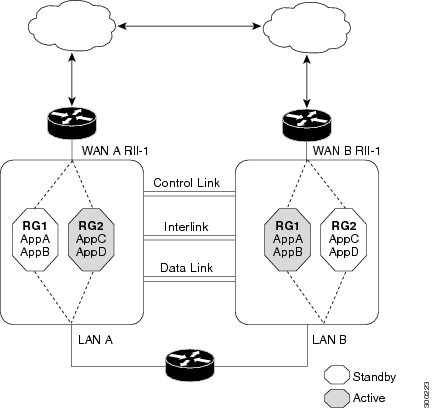
The figure below shows an asymmetric routing scenario with a separate asymmetric-routing interlink interface to divert packets to the active RG.

Figure 1. Asymmetric Routing Scenario

The following rules apply to asymmetric routing:

  • 1:1 mapping exists between the redundancy interface identifier (RII) and the interface.

  • 1:n mapping exists between the interface and an RG. (An asymmetric routing interface can receive traffic from and send traffic to multiple RGs. For a non asymmetric-routing interface (normal LAN interface), a 1:1 mapping exists between the interface and the RG.)

  • 1:n mapping exists between an RG and applications that use it. (Multiple applications can use the same RG).

  • 1:1 mapping exists between an RG and the traffic flow. The traffic flow must map only to a single RG. If a traffic flow maps to multiple RGs, an error occurs.

  • 1:1 or 1:n mapping can exist between an RG and an asymmetric-routing interlink as long as the interlink has sufficient bandwidth to support all the RG interlink traffic.

Asymmetric routing consists of an interlink interface that handles all traffic that is to be diverted. The bandwidth of the asymmetric-routing interlink interface must be large enough to handle all expected traffic that is to be diverted. An IPv4 address must be configured on the asymmetric-routing interlink interface, and the IP address of the asymmetric routing interface must be reachable from this interface.


Note

We recommend that the asymmetric-routing interlink interface be used for interlink traffic only and not be shared with high availability control or data interfaces because the amount of traffic on the asymmetric-routing interlink interface could be quite high.


Dual-Stack Firewalls

A dual-stack firewall is a firewall running IPv4 and IPv6 traffic at the same time. A dual-stack firewall can be configured in the following scenarios:
  • One firewall zone running IPv4 traffic and another running IPv6 traffic.

  • IPv4 and IPv6 coexist when deployed with stateful Network Address Translation 64 (NAT64). In this scenario, the traffic flows from IPv6 to IPv4 and vice versa.

  • The same zone pair allows both IPv4 and IPv6 traffic.

Asymmetric Routing Support in Firewalls

For intrabox asymmetric routing support, the firewall does a stateful Layer 3 and Layer 4 inspection of Internet Control Message Protocol (ICMP), TCP, and UDP packets. The firewall does a stateful inspection of TCP packets by verifying the window size and order of packets. The firewall also requires the state information from both directions of the traffic for stateful inspection. The firewall does a limited inspection of ICMP information flows. It verifies the sequence number associated with the ICMP echo request and response. The firewall does not synchronize any packet flows to the standby redundancy group (RG) until a session is established for that packet. An established session is a three-way handshake for TCP, the second packet for UDP, and informational messages for ICMP. All ICMP flows are sent to the active RG.

The firewall does a stateless verification of policies for packets that do not belong to the ICMP, TCP, and UDP protocols.

The firewall depends on bidirectional traffic to determine when a packet flow should be aged out and diverts all inspected packet flows to the active RG. Packet flows that have a pass policy and that include the same zone with no policy or a drop policy are not diverted.


Note

The firewall does not support the asymmetric-routing always-divert enable command that diverts packets received on the standby RG to the active RG. By default, the firewall forces all packet flows to be diverted to the active RG.


Asymmetric Routing in a WAN-LAN Topology

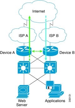
Asymmetric routing supports only a WAN-LAN topology. In a WAN-LAN topology, devices are connected through LAN interfaces on the inside and WAN interfaces on the outside. There is no control on the routing of return traffic received through WAN links. Asymmetric routing controls the routing of return traffic received through WAN links in a WAN-LAN topology. The figure below shows a WAN-LAN topology.
Figure 2. Asymmetric Routing in a WAN-LAN Topology

Checkpoint Facility Support for Application Redundancy

Checkpointing is the process of storing the current state of a device and using that information during restart when the device fails. The checkpoint facility (CF) supports communication between peers by using the Inter-Process Communication (IPC) protocol and the IP-based Stream Control Transmission Protocol (SCTP). CF also provides an infrastructure for clients or devices to communicate with their peers in multiple domains. Devices can send checkpoint messages from the active to the standby device.

Application redundancy supports multiple domains (also called groups) that can reside within the same chassis and across chassis. Devices that are registered to multiple groups can send checkpoint messages from one group to their peer group. Application redundancy supports interchassis domain communication. Checkpointing happens from an active group to a standby group. Any combination of groups can exist across chassis. The communication across chassis is through SCTP transport over a data link interface that is dedicated to application redundancy.

Note

Domains in the same chassis cannot communicate with each other.


How to Configure Interchassis High Availability Support in IPv6 Zone-Based Firewalls

Configuring a Redundancy Application Group and a Redundancy Group Protocol

Redundancy groups consist of the following configuration elements:
  • The amount by which the priority will be decremented for each object.

  • Faults (objects) that decrement the priority

  • Failover priority

  • Failover threshold

  • Group instance

  • Group name

  • Initialization delay timer

SUMMARY STEPS

  1. enable
  2. configure terminal
  3. redundancy
  4. application redundancy
  5. group id
  6. name group-name
  7. priority value [failover threshold value]
  8. preempt
  9. track object-number decrement number
  10. exit
  11. protocol id
  12. timers hellotime {seconds | msec msec} holdtime {seconds | msec msec}
  13. authentication {text string | md5 key-string [0 | 7] key [timeout seconds] | key-chain key-chain-name}
  14. bfd
  15. end

DETAILED STEPS

  Command or Action Purpose
Step 1

enable

Example:

Device> enable
Enables privileged EXEC mode.
  • Enter your password if prompted

Step 2

configure terminal

Example:

Device# configure terminal

Enters global configuration mode.

Step 3

redundancy

Example:

Device(config)# redundancy

Enters redundancy configuration mode.

Step 4

application redundancy

Example:

Device(config-red)# application redundancy

Configures application redundancy and enters redundancy application configuration mode.

Step 5

group id

Example:

Device(config-red-app)# group 1

Configures a redundancy group and enters redundancy application group configuration mode.

Step 6

name group-name

Example:

Device(config-red-app-grp)# name group1          

Specifies an optional alias for the protocol instance.

Step 7

priority value [failover threshold value]

Example:

Device(config-red-app-grp)# priority 100 failover threshold 50          

Specifies the initial priority and failover threshold for a redundancy group.

Step 8

preempt

Example:

Device(config-red-app-grp)# preempt          
Enables preemption on the redundancy group and enables the standby device to preempt the active device.
  • The standby device preempts only when its priority is higher than that of the active device.

Step 9

track object-number decrement number

Example:

Device(config-red-app-grp)# track 50 decrement 50          

Specifies the priority value of a redundancy group that will be decremented if an event occurs on the tracked object.

Step 10

exit

Example:

Device(config-red-app-grp)# exit          

Exits redundancy application group configuration mode and enters redundancy application configuration mode.

Step 11

protocol id

Example:

Device(config-red-app)# protocol 1          

Specifies the protocol instance that will be attached to a control interface and enters redundancy application protocol configuration mode.

Step 12

timers hellotime {seconds | msec msec} holdtime {seconds | msec msec}

Example:

Device(config-red-app-prtcl)# timers hellotime 3 holdtime 10           
Specifies the interval between hello messages sent and the time period before which a device is declared to be down.
  • Holdtime should be at least three times the hellotime.

Step 13

authentication {text string | md5 key-string [0 | 7] key [timeout seconds] | key-chain key-chain-name}

Example:

Device(config-red-app-prtcl)# authentication md5 key-string 0 n1 timeout 100          

Specifies authentication information.

Step 14

bfd

Example:

Device(config-red-app-prtcl)# bfd          
Enables the integration of the failover protocol running on the control interface with the Bidirectional Forwarding Detection (BFD) protocol to achieve failure detection in milliseconds.
  • BFD is enabled by default.

Step 15

end

Example:

Device(config-red-app-prtcl)# end          

Exits redundancy application protocol configuration mode and enters privileged EXEC mode.

Configuring Data, Control, and Asymmetric Routing Interfaces

In this task, you configure the following redundancy group (RG) elements:
  • The interface that is used as the control interface.

  • The interface that is used as the data interface.

  • The interface that is used for asymmetric routing. This is an optional task. Perform this task only if you are configuring asymmetric routing for Network Address Translation (NAT).


Note

Asymmetric routing, data, and control must be configured on separate interfaces.


SUMMARY STEPS

  1. enable
  2. configure terminal
  3. redundancy
  4. application redundancy
  5. group id
  6. data interface-type interface-number
  7. control interface-type interface-number protocol id
  8. timers delay seconds [reload seconds]
  9. asymmetric-routing interface type number
  10. asymmetric-routing always-divert enable
  11. end

DETAILED STEPS

  Command or Action Purpose
Step 1

enable

Example:

Device> enable 
Enables privileged EXEC mode.
  • Enter your password if prompted.

Step 2

configure terminal

Example:

Device# configure terminal 

Enters global configuration mode.

Step 3

redundancy

Example:

Device(config)# redundancy 

Enters redundancy configuration mode.

Step 4

application redundancy

Example:

Device(config-red)# application redundancy 

Configures application redundancy and enters redundancy application configuration mode.

Step 5

group id

Example:

Device(config-red-app)# group 1 

Configures a redundancy group (RG) and enters redundancy application group configuration mode.

Step 6

data interface-type interface-number

Example:

Device(config-red-app-grp)# data GigabitEthernet 0/0/1 

Specifies the data interface that is used by the RG.

Step 7

control interface-type interface-number protocol id

Example:

Device(config-red-app-grp)# control GigabitEthernet 1/0/0 protocol 1 
Specifies the control interface that is used by the RG.
  • The control interface is also associated with an instance of the control interface protocol.

Step 8

timers delay seconds [reload seconds]

Example:

Device(config-red-app-grp)# timers delay 100 reload 400 

Specifies the time required for an RG to delay role negotiations that start after a fault occurs or the system is reloaded.

Step 9

asymmetric-routing interface type number

Example:

Device(config-red-app-grp)# asymmetric-routing interface GigabitEthernet 0/1/1 

Specifies the asymmetric routing interface that is used by the RG.

Step 10

asymmetric-routing always-divert enable

Example:

Device(config-red-app-grp)# asymmetric-routing always-divert enable 

Always diverts packets received from the standby RG to the active RG.

Step 11

end

Example:

Device(config-red-app-grp)# end 

Exits redundancy application group configuration mode and enters privileged EXEC mode.

Configuring a Redundant Interface Identifier and Asymmetric Routing on an Interface


Note

  • You must not configure a redundant interface identifier (RII) on an interface that is configured either as a data interface or as a control interface.
  • You must configure the RII and asymmetric routing on both active and standby devices.
  • You cannot enable asymmetric routing on the interface that has a virtual IP address configured.

SUMMARY STEPS

  1. enable
  2. configure terminal
  3. interface type number
  4. redundancy rii id
  5. redundancy group id [decrement number]
  6. redundancy asymmetric-routing enable
  7. end

DETAILED STEPS

  Command or Action Purpose
Step 1

enable

Example:

Device> enable
Enables privileged EXEC mode.
  • Enter your password if prompted.

Step 2

configure terminal

Example:

Device# configure terminal

Enters global configuration mode.

Step 3

interface type number

Example:

Device(config)# interface GigabitEthernet 0/1/3

Selects an interface to be associated with the redundancy group (RG) and enters interface configuration mode.

Step 4

redundancy rii id

Example:

Device(config-if)# redundancy rii 600

Configures the redundancy interface identifier (RII).

Step 5

redundancy group id [decrement number]

Example:

Device(config-if)# redundancy group 1 decrement 20

Enables the RG redundancy traffic interface configuration and specifies the amount to be decremented from the priority when the interface goes down.

Note 

You need not configure an RG on the traffic interface on which asymmetric routing is enabled.

Step 6

redundancy asymmetric-routing enable

Example:

Device(config-if)# redundancy asymmetric-routing enable

Establishes an asymmetric flow diversion tunnel for each RG.

Step 7

end

Example:

Device(config-if)# end

Exits interface configuration mode and enters privileged EXEC mode.

Configuring an IPv6 Firewall

The steps to configure an IPv4 firewall and an IPv6 firewall are the same. To configure an IPv6 firewall, you must configure the class map in such a way that only an IPv6 address family is matched.

The match protocol command applies to both IPv4 and IPv6 traffic and can be included in either an IPv4 policy or an IPv6 policy.

SUMMARY STEPS

  1. enable
  2. configure terminal
  3. vrf-definition vrf-name
  4. address-family ipv6
  5. exit-address-family
  6. exit
  7. parameter-map type inspect parameter-map-name
  8. sessions maximum sessions
  9. exit
  10. ipv6 unicast-routing
  11. ip port-map appl-name port port-num list list-name
  12. ipv6 access-list access-list-name
  13. permit ipv6 any any
  14. exit
  15. class-map type inspect match-all class-map-name
  16. match access-group name access-group-name
  17. match protocol protocol-name
  18. exit
  19. policy-map type inspect policy-map-name
  20. class type inspect class-map-name
  21. inspect [parameter-map-name]
  22. end

DETAILED STEPS

  Command or Action Purpose
Step 1

enable

Example:

Device> enable
Enters privileged EXEC mode.
  • Enter your password if prompted.

Step 2

configure terminal

Example:

Device# configure terminal

Enters global configuration mode.

Step 3

vrf-definition vrf-name

Example:

Device(config)# vrf-definition VRF1

Configures a virtual routing and forwarding (VRF) routing table instance and enters VRF configuration mode.

Step 4

address-family ipv6

Example:

Device(config-vrf)# address-family ipv6

Enters VRF address family configuration mode and configures sessions that carry standard IPv6 address prefixes.

Step 5

exit-address-family

Example:

Device(config-vrf-af)# exit-address-family

Exits VRF address family configuration mode and enters VRF configuration mode.

Step 6

exit

Example:

Device(config-vrf)# exit

Exits VRF configuration mode and enters global configuration mode.

Step 7

parameter-map type inspect parameter-map-name

Example:

Device(config)# parameter-map type inspect ipv6-param-map

Enables a global inspect-type parameter map for the firewall to connect thresholds, timeouts, and other parameters that pertain to the inspect action, and enters parameter-map type inspect configuration mode.

Step 8

sessions maximum sessions

Example:

Device(config-profile)# sessions maximum 10000

Sets the maximum number of allowed sessions that can exist on a zone pair.

Step 9

exit

Example:

Device(config-profile)# exit

Exits parameter-map type inspect configuration mode and enters global configuration mode.

Step 10

ipv6 unicast-routing

Example:

Device(config)# ipv6 unicast-routing

Enables the forwarding of IPv6 unicast datagrams.

Step 11

ip port-map appl-name port port-num list list-name

Example:

Device(config)# ip port-map ftp port 8090 list ipv6-acl

Establishes a port to application mapping (PAM) by using the IPv6 access control list (ACL).

Step 12

ipv6 access-list access-list-name

Example:

Device(config)# ipv6 access-list ipv6-acl

Defines an IPv6 access list and enters IPv6 access list configuration mode.

Step 13

permit ipv6 any any

Example:

Device(config-ipv6-acl)# permit ipv6 any any

Sets permit conditions for an IPv6 access list.

Step 14

exit

Example:

Device(config-ipv6-acl)# exit

Exits IPv6 access list configuration mode and enters global configuration mode.

Step 15

class-map type inspect match-all class-map-name

Example:

Device(config)# class-map type inspect match-all ipv6-class

Creates an application-specific inspect type class map and enters QoS class-map configuration mode.

Step 16

match access-group name access-group-name

Example:

Device(config-cmap)# match access-group name ipv6-acl

Configures the match criteria for a class map on the basis of the specified ACL.

Step 17

match protocol protocol-name

Example:

Device(config-cmap)# match protocol tcp

Configures a match criterion for a class map on the basis of the specified protocol.

Step 18

exit

Example:

Device(config-cmap)# exit

Exits QoS class-map configuration mode and enters global configuration mode.

Step 19

policy-map type inspect policy-map-name

Example:

Device(config)# policy-map type inspect ipv6-policy

Creates a protocol-specific inspect type policy map and enters QoS policy-map configuration mode.

Step 20

class type inspect class-map-name

Example:

Device(config-pmap)# class type inspect ipv6-class

Specifies the traffic class on which an action is to be performed and enters QoS policy-map class configuration mode.

Step 21

inspect [parameter-map-name]

Example:

Device(config-pmap-c)# inspect ipv6-param-map

Enables stateful packet inspection.

Step 22

end

Example:

Device(config-pmap-c)# end

Exits QoS policy-map class configuration mode and enters privileged EXEC mode.

Configuring Zones and Zone Pairs for Asymmetric Routing

SUMMARY STEPS

  1. enable
  2. configure terminal
  3. zone security zone-name
  4. exit
  5. zone security zone-name
  6. exit
  7. zone-pair security zone-pair-name [source source-zone destination destination-zone]
  8. service-policy type inspect policy-map-name
  9. exit
  10. interface type number
  11. ipv6 address ipv6-address/prefix-length
  12. encapsulation dot1q vlan-id
  13. zone-member security zone-name
  14. end
  15. show policy-map type inspect zone-pair sessions

DETAILED STEPS

  Command or Action Purpose
Step 1

enable

Example:

Device> enable
Enters privileged EXEC mode.
  • Enter your password if prompted.

Step 2

configure terminal

Example:

Device# configure terminal

Enters global configuration mode.

Step 3

zone security zone-name

Example:

Device(config)# zone security z1

Creates a security zone and enters security zone configuration mode.

Step 4

exit

Example:

Device(config-sec-zone)# exit

Exits security zone configuration mode and enters global configuration mode.

Step 5

zone security zone-name

Example:

Device(config)# zone security z2

Creates a security zone and enters security zone configuration mode.

Step 6

exit

Example:

Device(config-sec-zone)# exit

Exits security zone configuration mode and enters global configuration mode.

Step 7

zone-pair security zone-pair-name [source source-zone destination destination-zone]

Example:

Device(config)# zone-pair security in-2-out source z1 destination z2

Creates a zone pair and enters security zone-pair configuration mode.

Step 8

service-policy type inspect policy-map-name

Example:

Device(config-sec-zone-pair)# service-policy type inspect ipv6-policy

Attaches a policy map to a top-level policy map.

Step 9

exit

Example:

Device(config-sec-zone-pair)# exit

Exits security zone-pair configuration mode and enters global configuration mode.

Step 10

interface type number

Example:

Device(config)# interface gigabitethernet 0/0/0.1

Configures a subinterface and enters subinterface configuration mode.

Step 11

ipv6 address ipv6-address/prefix-length

Example:

Device(config-subif)# ipv6 address 2001:DB8:2222:7272::72/64

Configures an IPv6 address based on an IPv6 general prefix and enables IPv6 processing on an interface or a subinterface.

Step 12

encapsulation dot1q vlan-id

Example:

Device(config-subif)# encapsulation dot1q 2

Sets the encapsulation method used by the interface.

Step 13

zone-member security zone-name

Example:

Device(config-subif)# zone-member security z1
Configures the interface as a zone member.
  • For the zone-name argument, you must configure one of the zones that you had configured using the zone security command.

  • When an interface is in a security zone, all traffic to and from that interface (except traffic going to the device or initiated by the device) is dropped by default. To permit traffic through an interface that is a zone member, you must make that zone part of the zone pair to which you apply a policy. If the policy permits traffic (via inspect or pass actions), traffic can flow through the interface.

Step 14

end

Example:

Device(config-subif)# end

Exits subinterface configuration mode and enters privileged EXEC mode.

Step 15

show policy-map type inspect zone-pair sessions

Example:

Device# show policy-map type inspect zone-pair sessions
Displays the stateful packet inspection sessions created because a policy map is applied on a specified zone pair.
  • The output of this command displays both IPv4 and IPv6 firewall sessions.

Configuration Examples for Interchassis High Availability Support in IPv6 Zone-Based Firewalls

Example: Configuring a Redundancy Application Group and a Redundancy Group Protocol

Device# configure terminal	
Device(config)# redundancy
Device(config-red)# application redundancy
Device(config-red-app)# group 1
Device(config-red-app-grp)# name group1
Device(config-red-app-grp)# priority 100 failover threshold 50
Device(config-red-app-grp)# preempt
Device(config-red-app-grp)# track 50 decrement 50
Device(config-red-app-grp)# exit
Device(config-red-app)# protocol 1
Device(config-red-app-prtcl)# timers hellotime 3 holdtime 10
Device(config-red-app-prtcl)# authentication md5 key-string 0 n1 timeout 100
Device(config-red-app-prtcl)# bfd
Device(config-red-app-prtcl)# end

Example: Configuring Data, Control, and Asymmetric Routing Interfaces

Device# configure terminal
Device(config)# redundancy 
Device(config-red)# application redundancy
Device(config-red-app)# group 1
Device(config-red-app-grp)# data GigabitEthernet 0/0/1
Device(config-red-app-grp)# control GigabitEthernet 1/0/0 protocol 1
Device(config-red-app-grp)# timers delay 100 reload 400 
Device(config-red-app-grp)# asymmetric-routing interface GigabitEthernet 0/1/1 
Device(config-red-app-grp)# asymmetric-routing always-divert enable
Device(config-red-app-grp)# end 

Example: Configuring a Redundant Interface Identifier and Asymmetric Routing on an Interface

Device# configure terminal
Device(config)# interface GigabitEthernet 0/1/3
Device(config-if)# redundancy rii 600
Device(config-if)# redundancy group 1 decrement 20
Device(config-if)# redundancy asymmetric-routing enable 
Device(config-if)# end

Example: Configuring an IPv6 Firewall


Device# configure terminal
Device(config)# vrf-definition VRF1
Device(config-vrf)# address-family ipv6
Device(config-vrf-af)# exit-address-family
Device(config-vrf)# exit
Device(config)# parameter-map type inspect ipv6-param-map
Device(config-profile)# sessions maximum 10000
Device(config-profile)# exit
Device(config)# ipv6 unicast-routing
Device(config)# ip port-map ftp port 8090 list ipv6-acl
Device(config)# ipv6 access-list ipv6-acl
Device(config-ipv6-acl)# permit ipv6 any any
Device(config-ipv6-acl)# exit
Device(config)# class-map type inspect match-all ipv6-class
Device(config-cmap)# match access-group name ipv6-acl
Device(config-cmap)# match protocol tcp
Device(config-cmap)# exit
Device(config)# policy-map type inspect ipv6-policy
Device(config-pmap)# class type inspect ipv6-class
Device(config-pmap-c)# inspect ipv6-param-map
Device(config-pmap-c)# end

Example: Configuring Zones and Zone Pairs for Asymmetric Routing

Device# configure terminal
Device(config)# zone security z1
Device(config-sec-zone)# exit
Device(config)# zone security z2
Device(config-sec-zone)# exit
Device(config)# zone-pair security in-to-out source z1 destination z2
Device(config-sec-zone-pair)# service-policy type inspect ipv6-policy
Device(config-sec-zone-pair)# exit
Device(config)# interface gigabitethernet 0/0/0.1
Device(config-if)# ipv6 address 2001:DB8:2222:7272::72/64
Device(config-if)# encapsulation dot1q 2
Device(config-if)# zone member security z1
Device(config-if)# end

Additional References for Interchassis High Availability Support in IPv6 Zone-Based Firewalls

Related Documents

Related Topic

Document Title

Cisco IOS commands

Cisco IOS Master Command List, All Releases

Firewall commands

Technical Assistance

Description

Link

The Cisco Support and Documentation website provides online resources to download documentation, software, and tools. Use these resources to install and configure the software and to troubleshoot and resolve technical issues with Cisco products and technologies. Access to most tools on the Cisco Support and Documentation website requires a Cisco.com user ID and password.

http://www.cisco.com/cisco/web/support/index.html

Feature Information for Interchassis High Availability Support in IPv6 Zone-Based Firewalls

The following table provides release information about the feature or features described in this module. This table lists only the software release that introduced support for a given feature in a given software release train. Unless noted otherwise, subsequent releases of that software release train also support that feature.

Use Cisco Feature Navigator to find information about platform support and Cisco software image support. To access Cisco Feature Navigator, go to www.cisco.com/go/cfn. An account on Cisco.com is not required.
Table 1. Feature Information for Interchassis High Availability Support in IPv6 Zone-Based Firewalls

Feature Name

Releases

Feature Information

Interchassis High Availability Support in IPv6 Zone-Based Firewalls

Cisco IOS XE Release 3.8S

The Interchassis High Availability Support in IPv6 Zone-Based Firewalls feature supports asymmetric routing in firewalls that run IPv4 and IPv6 traffic at the same time. Asymmetric routing supports the forwarding of packets from a standby redundancy group to the active redundancy group for packet handling. If this feature is not enabled, the return TCP packets forwarded to the device that did not receive the initial synchronization (SYN) message are dropped because they do not belong to any known existing session.

No commands were introduced or modified by this feature.