- Configuring RADIUS
- Framed-Route in RADIUS Accounting
- RFC-2867 RADIUS Tunnel Accounting
- RADIUS Centralized Filter Management
- RADIUS Debug Enhancements
- RADIUS Logical Line ID
- RADIUS Route Download
- RADIUS Server Load Balancing
- RADIUS Support of 56-Bit Acct Session-Id
- RADIUS Tunnel Preference for Load Balancing and Fail-Over
- RADIUS Server Reorder on Failure
- Finding Feature Information
- Prerequisites
- Restrictions
- Information About RADIUS Tunnel Preference for Load Balancing and Fail-Over
- How RADIUS Tunnel Preference for Load Balancing and Fail-Over is Configured
- Configuration Example for RADIUS Tunnel Preference for Load Balancing and Fail-Over
- Additional References
- Feature Information for RADIUS Tunnel Preference for Load Balancing and Fail-Over
- Glossary
RADIUS Tunnel Preference for Load Balancing and Fail-Over
The RADIUS Tunnel Preference for Load Balancing and Fail-Over feature provides industry-standard load balancing and fail-over functionality for an Layer 2 Tunnel Protocol network server (LNS), rather than requiring the use of a Cisco proprietary Vendor Specific Attribute (VSA). The feature conforms to the tunnel attributes that are to be used in a multivendor network environment as defined in RFC 2868, thereby eliminating interoperability issues among network access servers (NASs) manufactured by different vendors.
- Finding Feature Information
- Prerequisites
- Restrictions
- Information About RADIUS Tunnel Preference for Load Balancing and Fail-Over
- How RADIUS Tunnel Preference for Load Balancing and Fail-Over is Configured
- Configuration Example for RADIUS Tunnel Preference for Load Balancing and Fail-Over
- Additional References
- Feature Information for RADIUS Tunnel Preference for Load Balancing and Fail-Over
- Glossary
Finding Feature Information
Your software release may not support all the features documented in this module. For the latest feature information and caveats, see the release notes for your platform and software release. To find information about the features documented in this module, and to see a list of the releases in which each feature is supported, see the Feature Information Table at the end of this document.
Use Cisco Feature Navigator to find information about platform support and Cisco software image support. To access Cisco Feature Navigator, go to www.cisco.com/go/cfn. An account on Cisco.com is not required.
Prerequisites
Configuring VPDNs and HGW groups is beyond the scope of this document. See the Related Document section for more information.
Restrictions
The following restrictions and limitations apply to the RADIUS Tunnel Preference for Load Balancing and Fail-Over feature:
- This feature does not support VPDN dial-out networks; it is designed only for dial-in applications.
- The maximum number of LNSs allowed in the network is 1550, which is 50 per tag attribute group and a limit of 31 tags.
- This feature requires a RADIUS server implementation to support RFC 2868.
Information About RADIUS Tunnel Preference for Load Balancing and Fail-Over
The RADIUS Tunnel Preference for Load Balancing and Fail-Over feature provides load balancing and fail-over virtual private dialup network (VPDN) home gateway (HGW) groups in a standardized fashion. This feature introduces new software functionality; no new command is associated with this feature.
- Industry-Standard Rather Than Proprietary Attributes
- Load Balancing and Fail-Over in a Multivendor Network
- Related Features and Technologies
Industry-Standard Rather Than Proprietary Attributes
Until Cisco IOS Release 12.2(4)T, load balancing and fail-over functionality for a LNS was provided by the Cisco proprietary VSA. In a multivendor network environment, using VSA on a RADIUS server can cause interoperability issues among NASs manufactured by different vendors. Even though some RADIUS server implementations can send VSAs that the requesting NAS can understand, the user still must maintain different VSAs for the same purpose in a single-service profile.
A consensus regarding the tunnel attributes that are to be used in a multivendor network environment is defined in RFC 2868. In RFC 2868, Tunnel-Server-Endpoint, in conjunction with the Tunnel-Medium-Type, specifies the address to which the NAS should initiate a new session. If multiple Tunnel-Server-Endpoint attributes are defined in one tagged attribute group, they are interpreted as equal-cost load-balancing HGWs.
The Tunnel-Preference attribute defined in RFC 2868 can be used as a measure to form load balancing and fail-over HGW groups. When the Tunnel-Preference values of different tagged attribute groups are the same, the Tunnel-Server-Endpoint of those attribute groups is considered to have the same priority unless otherwise specified. When the Tunnel-Preference values of some attribute groups are higher (they have a lower preference) than other attribute groups, their Tunnel-Server-Endpoint attributes will have higher priority values. When an attribute group has a higher priority value, that attribute group will be used for fail-over in case the attribute groups with lower priority values are unavailable for the connections.
Until Cisco IOS Release 12.2(4)T, a specially formatted string would be transported within a Cisco VSA “vpdn:ip-addresses” string to a NAS for the purpose of HGW load balancing and fail-over. For example, 10.0.0.1 10.0.0.2 10.0.0.3/2.0.0.1 2.0.0.2 would be interpreted as IP addresses 10.0.0.1, 10.0.0.2, and 10.0.0.3 for the first group for load balancing. New sessions are projected to these three addresses based on the least-load-first algorithm. This algorithm uses its local knowledge to select an HGW that has the least load to initiate the new session. In this example, the addresses 2.0.0.1 and 2.0.0.2 in the second group have a lower priority and are applicable only when all HGWs specified in the first group fail to respond to the new connection request, thereby making 2.0.0.1 and 2.0.0.2 the fail-over addresses. See the section Configuration Example for RADIUS Tunnel Preference for Load Balancing and Fail-Over for an example of how to configure these fail-over addresses in a RADIUS tunnel profile.
Load Balancing and Fail-Over in a Multivendor Network
The RADIUS Tunnel Preference for Load Balancing and Fail-Over feature was designed for large multivendor networks that use VPDN Layer 2 tunnels over WAN links such as ATM and Ethernet, such as the configuration shown in the figure below.
| Figure 1 | Typical Load Balancing and Fail-Over in a Multivendor Network |
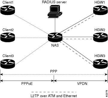
In the configuration shown in the figure above, the NAS uses tunnel profiles downloaded from the RADIUS server to establish VPDN Layer 2 tunnels for load balancing and fail-over. The Point-to-Point over Ethernet (PPPoE) protocol is used as the client to generate PPP sessions.
Related Features and Technologies
The RADIUS Tunnel Preference for Load Balancing and Fail-Over feature is used in VPDNs. Additionally, familiarity with the following technologies and protocols is recommended:
- ATM
- Ethernet
- L2TP and L2F
- PPP and PPPoE
- RADIUS servers
How RADIUS Tunnel Preference for Load Balancing and Fail-Over is Configured
This feature has no new configuration commands; however, see the next section for an example of how to implement the RADIUS Tunnel Preference for Load Balancing and Fail-Over feature in a RADIUS tunnel profile.
Configuration Example for RADIUS Tunnel Preference for Load Balancing and Fail-Over
The following example shows how to create RADIUS tunnel profiles:
net3 Password = "cisco" Service-Type = Outbound
        Tunnel-Type = :0:L2TP,
        Tunnel-Medium-Type = :0:IP,
        Tunnel-Server-Endpoint = :0:"1.1.3.1",
        Tunnel-Assignment-Id = :0:"1",
        Tunnel-Preference = :0:1,
        Tunnel-Password = :0:"welcome"
        Tunnel-Type = :1:L2TP,
        Tunnel-Medium-Type = :1:IP,
        Tunnel-Server-Endpoint = :1:"1.1.5.1",
        Tunnel-Assignment-Id = :1:"1",
        Tunnel-Preference = :1:1,
        Tunnel-Password = :1:"welcome"
        Tunnel-Type = :2:L2TP,
        Tunnel-Medium-Type = :2:IP,
        Tunnel-Server-Endpoint = :2:"1.1.4.1",
        Tunnel-Assignment-Id = :2:"1",
        Tunnel-Preference = :2:1,
        Tunnel-Password = :2:"welcome"
        Tunnel-Type = :3:L2TP,
        Tunnel-Medium-Type = :3:IP,
        Tunnel-Server-Endpoint = :3:"1.1.6.1",
        Tunnel-Assignment-Id = :3:"1",
        Tunnel-Preference = :3:1,
        Tunnel-Password = :3:"welcome"
See Information About RADIUS Tunnel Preference for Load Balancing and Fail-Over for more information on how fail-over addresses are selected in these profiles. See the Configuration Example for RADIUS Tunnel Preference for Load Balancing and Fail-Over for documents used create RADIUS tunnel profiles.
Additional References
The following sections provide references related to RADIUS Tunnel Preference for Load Balancing and Fail-Over feature.
Related Documents
| Related Topic |
Document Title |
|---|---|
| RADIUS |
“ Configuring RADIUS ” module. |
| RADIUS Attributes |
“ RADIUS Attributes Overview and RADIUS IETF Attributes ” module. |
| Virtual private dialup networks (VPDN) roadmap |
Cisco IOS VPDN Configuration Guide , Release 15.0. |
| Dial Technologies |
Cisco IOS Dial Technologies Configuration Guide , Release 12.4T |
| Broadband Access: PPP and Routed Bridge Encapsulation |
Cisco IOS Broadband Access Aggregation and DSL Configuration Guide , Release 12.4T |
Standards
| Standard |
Title |
|---|---|
| None. |
-- |
MIBs
| MIB |
MIBs Link |
|---|---|
| None. |
To locate and download MIBs for selected platforms, Cisco IOS releases, and feature sets, use Cisco MIB Locator found at the following URL: |
RFCs
| RFC |
Title |
|---|---|
| RFC 2868 |
RADIUS Attributes for Tunnel Protocol Support |
Feature Information for RADIUS Tunnel Preference for Load Balancing and Fail-Over
The following table provides release information about the feature or features described in this module. This table lists only the software release that introduced support for a given feature in a given software release train. Unless noted otherwise, subsequent releases of that software release train also support that feature.
Use Cisco Feature Navigator to find information about platform support and Cisco software image support. To access Cisco Feature Navigator, go to www.cisco.com/go/cfn. An account on Cisco.com is not required.
| Table 1 | Feature Information for RADIUS Tunnel Preference for Load Balancing and Fail-Over |
| Feature Name |
Releases |
Feature Information |
|---|---|---|
| RADIUS Tunnel Preference for Load Balancing and Fail-Over |
12.2(4)T |
The RADIUS Tunnel Preference for Load Balancing and Fail-Over feature provides industry-standard load balancing and fail-over functionality for an Layer 2 Tunnel Protocol network server (LNS), rather than requiring the use of a Cisco proprietary Vendor Specific Attribute (VSA). The feature conforms to the tunnel attributes that are to be used in a multivendor network environment as defined in RFC 2868, thereby eliminating interoperability issues among network access servers (NASs) manufactured by different vendors. This feature was introduced in Cisco IOS Release 12.2(4)T. |
Glossary
HGW --home gateway. A gateway that terminates Layer 2 tunneling protocols such as L2TP.
home gateway --See HGW.
L2TP --Layer 2 Tunnel Protocol. An Internet Engineering Task Force (IETF) standards track protocol defined in RFC 2661 that provides tunneling of PPP. Based upon the best features of L2F and PPTP, L2TP provides an industry-wide interoperable method of implementing VPDN.
L2TP network server--See LNS.
Layer 2 Tunnel Protocol --See L2TP.
LNS --L2TP network server. A node that acts as one side of an L2TP tunnel endpoint and is a peer to the NAS or L2TP access concentrator (LAC). The LNS is the logical termination point of a PPP session that is being tunneled from the remote system by the access server. Analogous to the Layer 2 Forwarding (L2F) HGW.
NAS --network access server. Cisco platform or collection of platforms that interfaces between the packet world (the Internet, for example) and the circuit world (the public switched telephone network, for example).
network access server --See NAS.
Request for Comments --See RFCs.
RFCs --Request for Comments. A series of notes about the Internet collected by the Internet Engineering Task Force (IETF). Started in 1969, the IETF is a large open international community of network designers, operators, vendors, and researchers concerned with the evolution of the Internet architecture. RFCs define many aspects of computer communication, focusing on networking protocols, procedures, programs, and concepts.
virtual private dialup network --See VPDN.
VPDN --virtual private dialup network. Enables IP traffic to travel securely over a public TCP/IP network by encrypting all traffic from one network to another.
Any Internet Protocol (IP) addresses and phone numbers used in this document are not intended to be actual addresses and phone numbers. Any examples, command display output, network topology diagrams, and other figures included in the document are shown for illustrative purposes only. Any use of actual IP addresses or phone numbers in illustrative content is unintentional and coincidental. © 2001-2009 Cisco Systems, Inc. All rights reserved.
Cisco and the Cisco Logo are trademarks of Cisco Systems, Inc. and/or its affiliates in the U.S. and other countries. A listing of Cisco's trademarks can be found at www.cisco.com/go/trademarks. Third party trademarks mentioned are the property of their respective owners. The use of the word partner does not imply a partnership relationship between Cisco and any other company. (1005R)
Any Internet Protocol (IP) addresses and phone numbers used in this document are not intended to be actual addresses and phone numbers. Any examples, command display output, network topology diagrams, and other figures included in the document are shown for illustrative purposes only. Any use of actual IP addresses or phone numbers in illustrative content is unintentional and coincidental.
 Feedback