Call Legs
A traditional voice call over the public switched telephone network (PSTN) uses a dedicated 64K circuit end to end. In contrast, a voice call over the packet network is made up of discrete segments or call legs. A call leg is a logical connection between two routers or between a router and a telephony device. A voice call comprises four call legs, two from the perspective of the originating router and two from the perspective of the terminating router, as shown in the figure below.

A dial peer is associated with each call leg. Attributes that are defined in a dial peer and applied to the call leg include the codec, quality of service (QoS), voice activity detection (VAD), and fax rate. To complete a voice call, you must configure a dial peer for each of the four call legs in the call connection.
Depending on the call leg, a call is routed using one of the two types of dial peers:
-
Plain old telephone system (POTS)--Dial peer that defines the characteristics of a traditional telephony network connection. POTS dial peers map a dialed string to a specific voice port on the local router, normally the voice port connecting the router to the local PSTN, PBX, or telephone.
-
Voice-network--Dial peer that defines the characteristics of a packet network connection. Voice-network dial peers map a dialed string to a remote network device, such as the destination router that is connected to the remote telephony device.
Both POTS and voice-network dial peers are needed to establish voice connections over a packet network.
When a voice call comes into the router, the router must match dial peers to route the call. For inbound calls from a POTS interface that are being sent over the packet network, the router matches a POTS dial peer for the inbound call leg and a voice-network dial peer for the outbound call leg. For calls coming into the router from the packet network, the router matches an outbound POTS dial peer to terminate the call and an inbound voice-network dial peer for features such as codec, VAD, and QoS.
The figure below shows the call legs and associated dial peers necessary to complete a voice call.

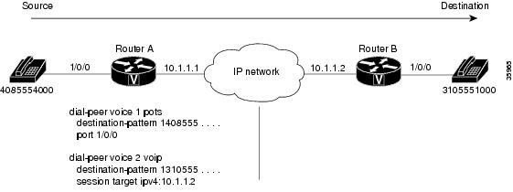
The following configurations show an example of a call being made from 4085554000 to 3105551000. The figure below shows the inbound POTS dial peer and the outbound voice over IP (VoIP) dial peer that are configured on the originating router. The POTS dial peer establishes the source of the call (via the calling number or voice port), and the voice-network dial peer establishes the destination by associating the dialed number with the network address of the remote router.

In this example, the dial string 14085554000 maps to telephone number 555-4000, with the digit 1 plus the area code 408 preceding the number. When you configure the destination pattern, set the string to match the local dialing conventions.
The figure below shows the inbound VoIP dial peer and outbound POTS dial peer that are configured on the terminating router to complete the call. Dial peers are of local significance only.

In the previous configuration examples, the last four digits in the VoIP dial peer’s destination pattern were replaced with wildcards. Which means that from Router A, calling any telephone number that begins with the digits "1310555" will result in a connection to Router B. This behavior implies that Router B services all numbers beginning with those digits. From Router B, calling any telephone number that begins with the digits "1408555" will result in a connection to Router A. This behavior implies that Router A services all numbers beginning with those digits.
 Note |
It is not always necessary to configure the inbound dial peers. If the router is unable to match a configured dial peer for the inbound call leg, it uses an internally defined default POTS or voice-network dial peer to match inbound voice calls. In the example shown in the figure above, dial peer 2 is required only when making a call from Router B to Router A. |
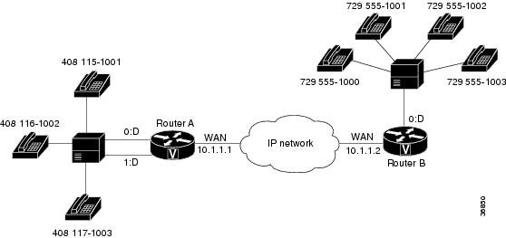
The only exception to the previous example occurs when both POTS dial peers share the same router, as shown in the figure below. In this circumstance, you do not need to configure a voice-network dial peer.

This type of configuration is similar to the configuration used for hairpinning, which occurs when a voice call destined for the packet network is instead routed back over the PSTN because the packet network is unavailable.

 Feedback