|
OTV—Overlay Transport Virtualization
|
Cisco IOS XE Release 3.5S
|
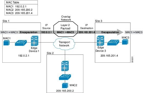
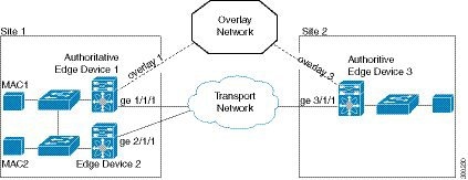
OTV provides Layer 2 connectivity between remote network sites by using MAC-address-based routing and IP-encapsulated forwarding
across a transport network to provide support for applications that require Layer 2 adjacency.
The following commands were introduced or modified:
authentication key-chain (OTV) ,
authentication mode (OTV) ,
authentication send-only (OTV) ,
clear otv arp-nd ,
clear otv isis ,
clear otv isis lspfull ,
clear otv isis neighbors ,
clear otv isis rib ,
debug l2fib ,
debug mlrib common ,
debug mlrib layer2 ,
debug otv ,
debug otv isis ,
debug platform software l2fib ,
debug platform software otv ,
debug platform hardware qfp feature otv client ,
debug platform hardware qfp feature otv datapath ,
hostname dynamic (OTV) ,
interface overlay ,
log-adjacency-changes (OTV) ,
lsp-gen-intervaL (OTV) ,
lsp-mtu (OTV) ,
lsp-refresh-interval (OTV) ,
max-lsp-lifetime (OTV) ,
nsf (OTV) ,
otv active-source ,
otv control-group ,
otv data-group ,
otv filter-fhrp ,
otv fragmentation ,
otv isis authentication ,
otv isis csnp-interval ,
otv isis hello-interval ,
otv isis hello-multiplier ,
otv isis hello padding ,
otv isis lsp-interval ,
otv isis metric ,
otv isis overlay ,
otv isis priority ,
otv isis retransmit-interval ,
otv isis retransmit-throttle-interval ,
otv isis site
otv join-interface ,
otv mac flood ,
otv site bridge-domain ,
otv site-identifier ,
otv suppress arp-nd ,
otv vpn-name ,
prc-interval (OTV) ,
show l2fib ,
show mlrib common log ,
show mlrib layer2 log ,
show otv ,
show otv adjacency ,
show otv arp-nd-cache ,
show otv data-group ,
show otv isis database ,
show otv isis hostname ,
show otv isis lsp-log ,
show otv isis neighbors ,
show otv isis nsf ,
show otv isis protocol ,
show otv isis rib ,
show otv isis spf-log ,
show otv isis vlan-database ,
show otv log ,
show otv mroute ,
show otv route ,
show otv site ,
show otv statistics ,
show otv summary ,
show otv vlan ,
show platform hardware qfp feature otv client interface ,
show platform software l2fib fp ,
show platform software l2fib rp ,
show platform software otv fp ,
skeptical interval (OTV) ,
spf-interval (OTV) .
|


 Feedback