- Finding Feature Information
- Prerequisites for OTV
- Restrictions for OTV
- Information About OTV
- OTV Features
- Creating an Overlay Interface
- Associating an Overlay Interface with a Physical Interface
- Configuring a Multicast Group Address
- Configuring a VLAN over an Overlay Interface
- Configuring the Site Bridge Domain and the Site Identifier
- Configuring Authentication for OTV IS-IS Hellos
- Configuring Authentication for OTV IS-IS PDUs
- Disabling ARP Caching
- Tuning OTV Parameters
Configuring Overlay Transport Virtualization
Overlay Transport Virtualization (OTV) is a MAC-in-IP method that extends Layer 2 connectivity across a transport network infrastructure. OTV provides Layer 2 connectivity between remote network sites by using MAC-address-based routing and IP-encapsulated forwarding across a transport network to provide support for applications that require Layer 2 adjacency.
The OTV application (also known as OTV) is one of the modules of the OTV architecture in Cisco software. OTV interacts with the following other modules of the OTV architecture in Cisco IOS software:
Layer 2 Intermediate System-to-Intermediate System (IS-IS)
Ethernet infrastructure
IP tunnel infrastructure
Layer 2 Forwarding Information Base (L2FIB)
Multilayer Routing Information Base (MLRIB)
Ethernet Operation, Administration, and Maintenance (OAM)
Internet Group Management Protocol (IGMP)
Address Resolution Protocol (ARP)
You deploy OTV on edge devices in each site. OTV requires no other changes to the sites or to the transport network.
- Finding Feature Information
- Prerequisites for OTV
- Restrictions for OTV
- Information About OTV
- How to Configure OTV
- Configuration Examples for OTV Features
- Verifying the OTV Configuration
- Additional References
- Feature Information for OTV
Finding Feature Information
Your software release may not support all the features documented in this module. For the latest caveats and feature information, see Bug Search Tool and the release notes for your platform and software release. To find information about the features documented in this module, and to see a list of the releases in which each feature is supported, see the feature information table.
Use Cisco Feature Navigator to find information about platform support and Cisco software image support. To access Cisco Feature Navigator, go to www.cisco.com/go/cfn. An account on Cisco.com is not required.
Prerequisites for OTV
You must have basic understanding of routing, switching, and multicast concepts.
Restrictions for OTV
-
Configure the join interface and all Layer 3 interfaces that face the IP core between the OTV edge devices with the highest maximum transmission unit (MTU) size supported by the IP core. OTV sets the Don’t Fragment (DF) bit in the IP header for all OTV control and data packets so that the core cannot fragment these packets.
-
Ensure that PIM is not enabled on the join interface; enable only passive PIM on the join interface. Configure SSM for the OTV data group multicast address range by using the ip pim passive command.
-
Ensure that a site identifier is configured and is the same for all edge devices in a same site. OTV brings down all overlays and generates a system message when it detects a mismatched site identifier from a neighbor edge device.
-
Only one internal interface (site-facing interface) can be configured on an edge device for all the overlays, multiple internal interface's are not supported.
-
Only physical interfaces/sub-interfaces/port-channel can be used as join-interfaces, GRE tunnels and loopback interfaces are not supported.
-
OTV is compatible only with a transport network configured for IPv4. IPv6 is not supported.
-
OTV cannot be configured on the same router on which Multiprotocol Label Switching (MPLS) is configured. If you try to configure an overlay interface on a router where MPLS is already configured, OTV creation will fail. Similarly, if you try to create an MPLS on a router where OTV is configured, MPLS creation will fail. You can remove a failed overlay interface configuration by using the no interface overlay x command.
-
The transport network must support the Protocol Independent Multicast (PIM) sparse mode (Any Source Multicast [ASM]) for the provider multicast group and Source Specific Multicast (SSM) for the delivery group.
-
If the device is not configured with OTV, the show bridge-domain command does not display any output.
-
Overlay Transport Virtualization (OTV) and Cisco Unified Border Element (Cisco UBE) cannot interoperate with each other on Cisco IOS XE software.
Information About OTV
Functions of OTV
Maintains a list of overlays
Maintains a list of configured overlay parameters such as name, multicast address, encapsulation type, authentication, and OTV feature sets
Maintains the state of the overlay interface
Maintains the status of OTV VLAN membership from Ethernet infrastructure and the state of the authoritative edge device (AED) from IS-IS
Maintains a database of overlay adjacencies as reported by IS-IS
Maintains IP tunnel information and manages the encapsulation for data sent on the overlay network
Manages delivery groups (DGs) for each overlay by snooping multicast traffic and monitoring traffic streams for active DGs
Configures, starts, and stops the OTV IS-IS instance
Interfaces with IP multicast to join provider multicast groups for each overlay
OTV Terms
OTV Overlay Network
An OTV overlay network provides Layer 2 connectivity between remote sites over a transport network. An overlay network consists of one or more edge devices in each site. The sites are interconnected using a control-plane protocol across the transport network.
The figure below shows two sites connected through edge devices to a transport network to create a virtual overlay network.

An overlay network maps MAC addresses of the hosts at a site to their respective edge devices IP addresses. After OTV identifies the edge device to which a Layer 2 frame is to be sent, OTV encapsulates the frame and sends the resulting IP packet by using the transport network routing protocols.
OTV can support more than one overlay network running IPv4 unicast forwarding or multicast flooding. Each overlay network can support more than one unique VLAN.
 Note | OTV does not extend Spanning Tree Protocol (STP) across sites. Each site runs its own STP instead of all sites being included in a large STP domain. This per-site STP topology allows the use of different STP modes, such as Per-VLAN Spanning Tree (PVST), Rapid-PVST, or Multiple Spanning Tree (MST), in each site. |
- Edge Devices
- Site-to-Site Connectivity
- Overlay Networks Mapping to Multicast Groups
- OTV Packet Flow
- Mobility
- Sample OTV Topologies
Edge Devices
Each site consists of one or more edge devices and other internal routers, switches, or servers. OTV is configured only on an edge device. The OTV configuration is completely transparent to the rest of the site. For example, information about MAC learning, STP root bridge placement, and STP mode is transparent. An edge device has an internal interface that is part of the Layer 2 network and an external interface that is reachable through IP in the transport network.
An edge device performs typical Layer 2 learning and forwarding on its internal interface and transmits and receives encapsulated Layer 2 traffic on it's join interface through the transport network. An edge device sends and receives control-plane traffic through the join interface. The control-plane traffic exchanges reachability information between remote sites to build up a table that maps MAC addresses to the join interface IP address of the edge device that is local to that site.
Site-to-Site Connectivity
OTV builds Layer 2 reachability information by communicating between edge devices with the overlay protocol. The overlay protocol forms adjacencies with all edge devices. After each edge device is adjacent with all its peers in an overlay network, the edge devices share MAC address reachability information with other edge devices that participate in the same overlay network.
OTV discovers edge devices through dynamic neighbor detection, which leverages the multicast support of the core.
Overlay Networks Mapping to Multicast Groups
For transport networks that support IP multicast, one multicast address (the control-group address) is used to encapsulate and exchange OTV control-plane protocol updates. Each edge device that participates in a particular overlay network shares the same control-group address with all other edge devices of the same overlay network. As soon as a control-group, data-group address and a join interface are configured on an edge device, the edge device sends an IGMP report message to join the control group. Edge devices act as hosts in the multicast network and send multicast IGMP report messages to the assigned multicast group address.
As in traditional link-state routing protocols, edge devices exchange OTV control-plane hellos to build adjacencies with other edge devices in the overlay network. After adjacencies are established, OTV control-plane link-state packets (LSPs) communicate MAC-to-IP mappings to adjacent edge devices. These LSPs contain the IP address of the remote edge device, VLAN IDs, and the learned MAC addresses that are reachable through that edge device.
Edge devices participate in data-plane learning on internal interfaces to build up the list of MAC addresses that are reachable within their site. OTV sends these locally learned MAC addresses in the OTV control-plane updates.
OTV Packet Flow
When an edge device receives a Layer 2 frame on an internal interface, OTV performs the MAC table lookup based on the destination address of the Layer 2 frame. If the frame is destined to a MAC address that is reachable locally, the frame is internally forwarded to that device. OTV performs no other actions and the processing of the frame is complete.
If the frame is destined to a MAC address learned over an overlay network, OTV performs the following tasks:
-
Strips the preamble and frame check sequence (FCS) from the Layer 2 frame.
-
Adds an OTV header to the Layer 2 frame and copies the 802.1Q information into the OTV header.
-
Adds the IP address to the packet based on the initial MAC address table lookup. This IP address is used as the destination address for the IP packet that is sent over the transport network.
OTV traffic appears as IP traffic to the transport network.
At the destination site, the edge device performs the reverse operation and presents the original Layer 2 frame to the local site. The edge device, based on the local MAC address table forwards the frame on its internal interface.
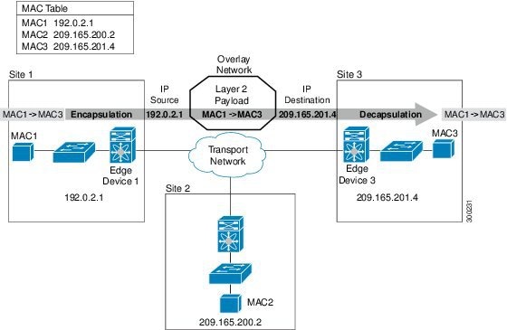
In the figure above, Site 1 communicates with Site 3 over the overlay network. Edge Device 1 receives the Layer 2 frame from MAC1 and looks up the destination MAC address, MAC3, in the MAC table. The edge device encapsulates the Layer 2 frame in an IP packet with the IP destination address set for Edge Device 3 (209.165.201.4). When Edge Device 3 receives the IP packet, the edge device strips off the IP header and sends the original Layer 2 frame over it's internal interface to reach the host having MAC address MAC3.
Mobility
OTV uses a metric value to support seamless MAC mobility.
When an AED learns a new MAC address, the AED advertises the new address in OTV control-plane updates with a metric value of one if no other edge device has advertised that MAC address before.
In the case of a mobile MAC address, an AED advertises the newly learned, local MAC address with a metric value of zero. This metric value signals the remote edge device to stop advertising that MAC address. After the remote edge device stops advertising the moved MAC address, the AED that contains the new MAC address changes the metric value to one.
Virtual machine (VM) mobility is one common example of MAC mobility. VM mobility occurs when the virtual machine moves from one site to another. OTV detects this change based on the changed advertisement of the mobile MAC address.
Sample OTV Topologies
You can use OTV to connect remote sites in multiple topologies.
Single-Homed Network
In this sample topology, both sites are connected over a common transport network. The edge devices in both the sites have an overlay interface configured (interface overlay 1 and interface overlay 2) with the same control-group address, which makes both the edge devices join a common overlay network.
Multiple Overlay Networks
You can configure an edge device in more than one overlay network. Each overlay network use different control and data group multicast addresses.

In the figure above, Site 3 connects to Site 1 over Overlay Network 1 through overlay interface 3 on Edge Device 3. Site 3 also connects to Site 2 over Overlay Network 2 through overlay interface 4 on Edge Device 3. Each overlay network has different control-group and data-group addresses.
Note | The VLAN's extended across different overlay network's should be unique. |
Site 3 uses Edge Device 3 to connect to both the overlay networks—Overlay Network 1 and Overlay Network 2. Edge Device 3 associates the same physical interface for both the overlay networks.
Multihomed Sites and Load Balancing
For resiliency and load balancing, a site can have multiple edge devices.
When more than one edge device exists in a site and both participate in the same overlay network, the site is considered multihomed. For the VLANs that are extended using OTV, one edge device is elected as an AED on a per-VLAN basis. OTV leverages a local VLAN to establish an adjacency between edge devices on their internal interfaces. The local VLAN that is shared by the internal interfaces is the site VLAN. The adjacency establishment over the site VLAN determines which edge device is authoritative for what VLANs.
Load balancing is achieved because each edge device is authoritative for a subset of all VLANs that are transported over the overlay. Link utilization to and from the transport is optimized.
The figure below shows the AED that is selected for a multihomed site in an overlay network.
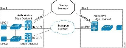
In the figure above, Site 1 is a multihomed site with two physical interfaces connected to the transport network.
Dual Site Adjacency
Dual site adjacency includes adjacency discovery over the overlay network and in the existing site VLAN. Dual site adjacency introduces additional resiliency and loop prevention. Loops may be caused by site VLAN partition or misconfiguration. Dual site adjacency also uses forwarding readiness notifications to detect when neighbor edge devices in the same site experience a change such as local failures (for example, the site VLAN or extended VLANs going down or the join interface going down). These forwarding readiness notifications trigger an immediate AED election for the site.
OTV sends forwarding readiness notifications to all neighbors of an edge device in the following isolation states:
Site isolation: All extended VLANs on an edge device go down.
Core isolation: All overlay adjacencies go down.
The dual site adjacency state results from the most recent adjacency state for either the overlay or the site VLAN adjacency. OTV determines AED election based on active dual site adjacencies only. An inactive dual site adjacency is ignored for AED election.
You must configure the same site identifier for all edge devices in a site. OTV advertises this site identifier in the IS-IS hello packets sent over the overlay network and on the local site VLAN. The combination of the IS-IS system ID and site identifier uniquely identifies the edge devices in a site.
OTV Features
The OTV control-plane creates adjacencies between remote sites to provide Layer 2 connectivity over a transport network. An OTV network performs the following functions:
-
Discovers remote sites and builds a control-protocol adjacency
-
Shares MAC routing information across an overlay network
An overlay network consists of one or more logical overlay interfaces that are configured on an edge device in each remote site that connects to the physical transport network. You associate the logical overlay interface with a physical interface (join-interface) that connects to the transport network. The OTV control plane is responsible for discovering edge devices in remote sites, creating control-protocol adjacencies to these sites, and establishing protocol adjacencies among the sites. The OTV control-plane protocol uses the IS-IS protocol to establish adjacencies and exchange MAC reachability across an overlay network.
Note | You do not need to configure IS-IS to use OTV. IS-IS is enabled in the background after OTV is enabled. |
The OTV control-plane protocol also sends and receives MAC routing updates between remote sites and updates the Routing Information Base (RIB) with these MAC-to-IP address pairs.
- Overlay Interface
- MAC Address Learning
- MAC Address Reachability Updates
- Multicast Group Addresses and IGMP Snooping
- ARP Cache
- High Availability
- OTV IS-IS
Overlay Interface
An overlay interface is a logical interface that connects to remote edge devices in an overlay network through an associated physical interface (join interface) on the transport network. From the perspective of MAC-based forwarding in a site, an overlay interface is simply another bridged interface. As a bridged interface, unicast MAC addresses are associated with an overlay interface. An overlay interface is eligible for inclusion in the Outbound Interface List (OIL) for different multicast groups. However, no STP packets are forwarded over an overlay interface. Unknown unicast packets are also not flooded on an overlay interface. From the perspective of IP transport, an overlay interface is not visible.
OTV encapsulates Layer 2 frames in IP packets and transmits them over the transport network via the join interface.
The following commands must be configured for an overlay interface to be in the up state:
MAC Address Learning
OTV learns MAC-to-IP address pairs from the following:
-
MAC address learning on internal interface
-
OTV control-plane updates over an overlay network
-
Multicast address learning through IGMP snooping
OTV edge devices snoop IGMP traffic and issue a Group Membership-link-state packet (GM-LSP) to advertise the presence of receivers to remote edge devices. The remote edge devices include the overlay interface in the Outbound Interface List (OIL) for the corresponding multicast group. OTV does not program multicast MAC addresses in the forwarding tables but rather updates the OIL state as necessary.
All learned MAC addresses are stored in the RIB with the associated remote IP addresses.
MAC Address Reachability Updates
The OTV control plane uses IS-IS link-state packets (LSPs) to propagate MAC address to IP address mappings to all edge devices in an overlay network. These address mappings contain the MAC address, VLAN ID, and the associated IP address of the edge device that the MAC address is reachable from.
An AED uses IGMP snooping to learn all multicast IP addresses in the local site. OTV includes these IP addresses in a special GM-LSP that is sent to remote edge devices in an overlay network.
Multicast Group Addresses and IGMP Snooping
OTV uses the control-group multicast address that is assigned from the transport network to create a unique multicast group between remote sites on an overlay network. Each edge device in an overlay network acts as a multicast host and sends an IGMP report message to join the control-group multicast address. OTV sends encapsulated OTV control-plane hello messages and MAC routing updates across this multicast group.
OTV uses IGMP snooping and group membership advertisements (GM-LSPs) to learn all multicast group members from remote sites. OTV also uses IGMP snooping to detect all multicast groups in a local site.
ARP Cache
OTV can suppress unnecessary ARP messages from being sent over an overlay network. OTV builds a local Layer 3-to-Layer 2 mapping for remote hosts. Any ARP requests from local hosts are served by this ARP cache.
High Availability
OTV supports stateless switchovers. A stateful switchover occurs when the active supervisor switches to the standby supervisor. There may be a few seconds of traffic loss while the OTV tunnel is recreated following a switchover.
OTV IS-IS
OTV uses the IS-IS protocol for control-plane learning of MAC entries. The OTV IS-IS component is responsible for transporting MAC information across all VPN sites. It carries unicast and multicast MAC information encoded in type, length, values (TLVs).
On the internal interface, OTV IS-IS is responsible for sending IS-IS hello (IIH) packets on the site VLAN by using a multicast MAC destination address. Using a multicast MAC address ensures that all Layer 2 switches in a site forward the packet and that the packet reaches all other OTV edge devices. Each site has a configured site ID. The site ID is advertised by each edge device in these IS-IS hello messages. The site ID is used to identify all edge devices belonging to the same site. IS-IS assigns an AED for each VLAN. The AED for a VLAN is the edge device responsible for announcing local MACs for a given VLAN to remote sites and accepting packets destined for that VLAN.
On the overlay interface, OTV IS-IS is responsible for sending out IIH packets with site ID TLV on the multicast control-group. Using the control-group multicast ensures that all remote sites participating in the overlay network are automatically discovered and an adjacency is formed among all edge devices belonging to the same overlay network. OTV IS-IS also informs OTV whenever a new neighbor is discovered.
OTV IS-IS also handles fast MAC moves between remote sites and the local site and guards against fast oscillations in the event of misconfigurations where the same MAC address is used in multiple sites.
OTV IS-IS Instances
The creation of an overlay interface triggers the creation of an OTV IS-IS instance. OTV IS-IS supports multiple overlays. There is a one-to-one relationship between an OTV IS-IS instance and an overlay interface. OTV IS-IS discovers neighbors, forms adjacencies, and exchanges unicast MAC and multicast group information per overlay. All IS-IS databases, such as the adjacency database and the LSP database, are maintained per overlay.
OTV IS-IS forms only level-1 adjacencies. It advertises the primary IP address of the join interface in its hellos and protocol data units (PDUs). This address along with the system ID of the neighbor is added to OTV, which stores this information in its overlay adjacency database.
OTV IS-IS MLRIB Interactions
OTV IS-IS is a client of Multilayer Routing Information Base (MLRIB) for Layer 2. OTV IS-IS registers with MLRIB to get notifications for all local Layer 2 unicast and multicast address additions or deletions. Unicast MAC address information is put in OTV IS-IS LSPs, while multicast address information is put in OTV IS-IS multicast group PDUs for flooding to all remote sites.
Based on neighbor LSP advertisements, OTV IS-IS adds MAC reachability information for remote unicast and multicast group addresses to MLRIB. When OTV is disabled on a VLAN (the VLAN is removed from the list of OTV-advertised VLANs), OTV IS-IS withdraws the remote reachability information from MLRIB.
How to Configure OTV
- Creating an Overlay Interface
- Associating an Overlay Interface with a Physical Interface
- Configuring a Multicast Group Address
- Configuring a VLAN over an Overlay Interface
- Configuring the Site Bridge Domain and the Site Identifier
- Configuring Authentication for OTV IS-IS Hellos
- Configuring Authentication for OTV IS-IS PDUs
- Disabling ARP Caching
- Tuning OTV Parameters
Creating an Overlay Interface
An overlay interface is a logical interface that connects to remote edge devices in an overlay network through an associated physical or port-channel interface (join-interface) on the transport network. After creating an overlay interface, you must associate the overlay interface with a join interface and configure control and data-group multicast addresses. For more information, see the “Associating an Overlay Interface with a Join Interface” and “Configuring a Multicast Group Address” sections.
1.
enable
2.
configure
terminal
3.
interface overlay
interface
4.
no shutdown
5.
otv vpn-name
name
6.
description
string
7.
end
DETAILED STEPS
Associating an Overlay Interface with a Physical Interface
Before you associate an overlay interface with a physical interface, ensure that IGMP Version 3 (IGMPv3) is configured on the physical Layer 3 interface that you configure as the join interface.
After creating an overlay interface, perform this task to associate the overlay interface with a join interface. Define a physical Layer 3 interface as the join interface for the overlay interface, and associate the same with the overlay interface.
1.
enable
2.
configure
terminal
3.
interface overlay
interface
4.
otv join-interface
type
number
5.
end
DETAILED STEPS
To enable unicast and multicast IP forwarding on a join interface, perform the following tasks after creating the join interface:
-
Configure the IP address and mask for the join interface by using the ip address command.
-
Configure the join interface to operate in Protocol Independent Multicast (PIM) passive mode by using the ip pim passive command.
-
Enable IP multicast routing by using the ip multicast-routing distributed command.
-
Configure IGMPv3 on the join interface by using the ip igmp version 3 command.
-
The following commands are also necessary to be added globally to ensure multicast forwarding happens - these commands enable IGMP snooping on the internal interface:
ip igmp snooping querier version 3
ip igmp snooping querier
Configuring a Multicast Group Address
Perform this task to configure a unique multicast group address for each overlay network.
1.
enable
2.
configure
terminal
3.
interface overlay
interface
4.
otv control-group
multicast-address
5.
otv data-group
multicast-address/mask
6.
end
DETAILED STEPS
Configuring a VLAN over an Overlay Interface
Before configuring a VLAN over an overlay interface, ensure that there is connectivity for VLANs to be extended to the OTV edge device.
Ethernet service instances are configured with VLAN encapsulation on an overlay interface to define the VLANs that are part of an overlay network. MAC addresses learned on the service instances’ bridge domains are advertised to other edge devices on the overlay along with the service instances’ VLAN.
1.
enable
2.
configure
terminal
3.
interface overlay
interface
4.
service instance
interface
ethernet
5.
encapsulation dot1q
vlan-ID
6.
bridge-domain
bridge-domain-ID
7.
end
DETAILED STEPS
Configuring the Site Bridge Domain and the Site Identifier
A site bridge domain is used by OTV to identify the service instance where local hello messages should be sent. There should be an Ethernet service instance configured with the site bridge domain on the internal interface. OTV uses the configured VLAN encapsulation (if any) from this service instance to encapsulate local hello messages before sending out a message from the local interface.
A site identifier is advertised by each edge device in an overlay network and is used to identify all edge devices belonging to the same site. All edge devices in the same site should be configured with the same site identifier.
1.
enable
2.
configure
terminal
3.
otv site bridge-domain
bridge-domain-ID
4.
exit
5.
otv site-identifier
site-ID
6.
end
DETAILED STEPS
Example
The following sample output shows the configuration of overlay interface 1:
Device#show running-config interface gigabitEthernet 0/0/2
!
interface GigabitEthernet0/0/2
 description "Join Interface"
 ip address 209.165.201.1 255.255.255.224
 ip pim passive
 ip igmp version 3
 negotiation auto
end

Device#
Device#show running-config interface GigabitEthernet0/0/0
!
interface GigabitEthernet0/0/0
 description "Internal Interface"
 no ip address
 negotiation auto
 service instance 10 ethernet
  encapsulation dot1q 10
  bridge-domain 10
 !
 service instance 20 ethernet
  encapsulation dot1q 20
  bridge-domain 20
 !
Device#
Device#show otv overlay1
Overlay Interface Overlay1
 VPN name                 : overlay1
 VPN ID                   : 1
 State                    : UP
 Fwd-capable              : Yes
 Fwd-ready                : Yes
 AED-Server               : Yes
 Backup AED-Server        : No
 AED Capable              : Yes
 IPv4 control group       : 239.1.1.1
 Mcast data group range(s): 232.1.1.0/28
 Join interface(s)        : GigabitEthernet0/0/2
 Join IPv4 address        : 209.165.201.1
 Tunnel interface(s)      : Tunnel0
 Encapsulation format     : GRE/IPv4
 Site Bridge-Domain       : 10
 Capability               : Multicast-reachable
 Is Adjacency Server      : No
 Adj Server Configured    : No
 Prim/Sec Adj Svr(s)      : None

Device#
Device#show otv overlay 1 vlan

Overlay 1 VLAN Configuration Information
 Inst VLAN BD   Auth ED              State                Site If(s)
 0    20 20 *Device                  active               Gi0/0/0:SI20
 Total VLAN(s): 1

Device#
Configuring Authentication for OTV IS-IS Hellos
You can configure authentication for OTV IS-IS hello messages. OTV uses hello authentication to authenticate a remote site before OTV creates an adjacency to that remote site. Each overlay network uses a unique authentication key. An edge device creates an adjacency only with a remote site that shares the same authentication key and authentication method.
OTV supports the following authentication methods:
1.
enable
2.
configure
terminal
3.
interface overlay
interface
4.
otv isis
authentication mode {md5 |
text}
5.
otv isis authentication
key-chain
key-chain-name
6.
end
DETAILED STEPS
Configuring Authentication for OTV IS-IS PDUs
Configure OTV to authenticate all incoming OTV IS-IS PDUs.
1.
enable
2.
configure
terminal
3.
otv isis overlay
overlay-interface
4.
authentication mode {md5 |
text}
5.
authentication
key-chain
key-chain-name
6.
end
DETAILED STEPS
Disabling ARP Caching
An ARP cache is maintained by every OTV edge device and is populated by snooping ARP replies. Initial ARP requests are broadcast to all sites, but subsequent ARP requests are suppressed at the edge device and answered locally. OTV edge devices respond to ARP requests on behalf of remote hosts. Perform this task to allow ARP requests over an overlay network and to disable ARP caching on OTV edge devices.
1.
enable
2.
configure terminal
3.
interface overlay
interface
4.
no otv suppress arp-nd
5.
end
6.
show otv [overlay
overlay-interface]
arp-nd-cache
DETAILED STEPS
Tuning OTV Parameters
You can tune parameters for the overlay routing protocol.
Note | We recommend that only experienced users of OTV perform these configurations. |
1.
enable
2.
configure
terminal
3.
interface overlay
interface
4.
otv isis csnp-interval
seconds
5.
otv isis
hello-interval [seconds |
minimal]
6.
otv isis
hello-multiplier
multiplier
7.
no otv isis hello
padding
8.
otv isis lsp-interval
milliseconds
9.
otv isis
metric {metric |
maximum} [delay-metric |
expense-metric |
error-metric]
10.
otv isis priority
value
11.
end
DETAILED STEPS
Configuration Examples for OTV Features
Example: Configuring Overlay Interface and VLANs
Virtual Machine (VM1) should be reachable to the edge device 1. In this example, the MAC Address of VM1 is 000b.45b7.82c0.
The following example shows how to configure an edge device 1:
Device# 10:52 AM
ip multicast-routing distributed
!
ip igmp snooping querier version 3
ip igmp snooping querier
!
otv site bridge-domain 10
otv site-identifier 0000.0000.0001
!
interface overlay 1
 no shutdown
 otv vpn-name overlay1_site1
 otv control-group 239.1.1.1
 otv data-group 232.1.1.0/28
 otv join-interface GigabitEthernet 0/0/2
 !
 service instance 20 ethernet
  encapsulation dot1q 20
  bridge-domain 20
 !

interface GigabitEthernet 0/0/2
 description "Join Interface"
 ip address 209.165.201.1 255.255.255.224
 ip pim passive
 ip igmp version 3
 !
interface GigabitEthernet 0/0/0
 description "Internal Interface"
 !
 service instance 10 ethernet
  encapsulation dot1q 10
  bridge-domain 10
 !
 service instance 20 ethernet
  encapsulation dot1q 20
  bridge-domain 20
 !
ip pim ssm default
The following example shows how to configure a Switch 1:
SW1#show running-config interface GigabitEthernet 0/0
!
interface GigabitEthernet0/0
 description “Connected to Edge Device-1”
 switchport
 switchport trunk encapsulation dot1q
 switchport mode trunk
 mtu 9216
 no ip address
end

SW1#

SW1#show running-config interface GigabitEthernet 0/1
!
interface GigabitEthernet0/1
 description “Connected to VM1”
 switchport
 switchport access vlan 20
 switchport mode access
 mtu 9216
 no ip address
end

SW1#
Virtual Machine (VM2) should be reachable to the edge device 2. In this example, the MAC Address of VM2 is 0013.5f1c.6ec0.
ip multicast-routing distributed
!
ip igmp snooping querier version 3
ip igmp snooping querier
!
otv site bridge-domain 11
otv site-identifier 0000.0000.0002
!
interface overlay 1
 no shutdown
 otv vpn-name overlay1_site2
 otv control-group 239.1.1.1
 otv data-group 232.1.1.0/28
 otv join-interface GigabitEthernet 0/0/2
 !
 service instance 20 ethernet
  encapsulation dot1q 20
  bridge-domain 20
 !

interface GigabitEthernet 0/0/2
 description "Join Interface"
 ip address 209.165.201.2 255.255.255.224
 ip pim passive
 ip igmp version 3
 !
interface GigabitEthernet 0/0/0
 description "Internal Interface"
 !
 service instance 11 ethernet
  encapsulation dot1q 11
  bridge-domain 11
 !
 service instance 20 ethernet
  encapsulation dot1q 20
  bridge-domain 20
 !
ip pim ssm default
The following example shows how to configure a Switch 2:
SW2#show running-config interface GigabitEthernet 0/0
!
interface GigabitEthernet0/0
 description “Connected to Edge Device-2”
 switchport
 switchport trunk encapsulation dot1q
 switchport mode trunk
 mtu 9216
 no ip address
end

SW2#

SW2#show running-config interface GigabitEthernet 0/1
!
interface GigabitEthernet0/1
 description “Connected to VM2”
 switchport
 switchport access vlan 20
 switchport mode access
 mtu 9216
 no ip address
end

SW2#
The following example shows how to configure OTV using multicast.
ip multicast-routing distributed

ip igmp snooping querier version 3
ip igmp snooping querier

otv site bridge-domain 11
otv site-identifier 0000.0000.0002

interface GigabitEthernet0/0/0
 description "ACCESS / INTERNAL INTERFACE"
 no shutdown
 negotiation auto
 service instance 11 ethernet
  encapsulation dot1q 11
  bridge-domain 11
 !
 service instance 20 ethernet
  encapsulation dot1q 20
  bridge-domain 20

interface GigabitEthernet0/0/1
 no ip address
 no shutdown
 negotiation auto

router ospf 14
 router-id 14.14.14.1

interface GigabitEthernet0/0/2
 description "JOIN INTERFACE"
 encapsulation dot1Q 11
 ip address 209.165.201.1 255.255.255.224
 ip pim passive
 ip igmp version 3
 ip ospf 14 area 14

interface Overlay1
 no ip address
 no shutdown
 otv control-group 239.1.1.1
 otv data-group 232.1.1.0/28
 otv join-interface GigabitEthernet0/0/2
 service instance 11 ethernet
  encapsulation dot1q 11
  bridge-domain 11

CORE:

ip multicast-routing distributed

router ospf 14
 router-id 14.14.14.2

interface Loopback14
 ip address 14.14.14.14 255.255.255.255
 ip ospf 14 area 14

ip pim rp-address 14.14.14.14

interface GigabitEthernet0/0/0
 no ip address
 no shutdown
 negotiation auto

interface GigabitEthernet0/0/2
 description "CORE INTERFACE CONNECTED TO ED1"
 encapsulation dot1Q 14
 ip address 209.165.201.1 255.255.255.224
 ip pim sparse-mode
 ip igmp version 3
 ip ospf 14 area 14

interface GigabitEthernet0/0/0
 no ip address
 no shutdown
 negotiation auto

interface GigabitEthernet0/0/1
 description "CORE INTERFACE CONNECTED TO ED2"
 encapsulation dot1Q 11
 ip address 209.165.201.1 255.255.255.224
 ip pim sparse-mode
 ip igmp version 3
 ip ospf 14 area 14

ED2:

ip multicast-routing distributed

ip igmp snooping querier version 3
ip igmp snooping querier

otv site bridge-domain 12
otv site-identifier 0000.0000.0003

interface GigabitEthernet0/0/0
 description "ACCESS / INTERNAL INTERFACE"
 no shutdown
 negotiation auto
 service instance 11 ethernet
  encapsulation dot1q 11
  bridge-domain 11
 !
 service instance 12 ethernet
  encapsulation dot1q 12
  bridge-domain 12

interface GigabitEthernet0/0/3
 no ip address
 no shutdown
 negotiation auto

router ospf 14
 router-id 14.14.14.3

interface GigabitEthernet0/0/4
 description "JOIN INTERFACE"
 encapsulation dot1Q 11
 ip address 209.165.201.1 255.255.255.224
 ip pim passive
 ip igmp version 3
 ip ospf 14 area 14

interface Overlay11
 no ip address
 no shutdown
 otv control-group 239.1.1.1
 otv data-group 232.1.1.0/28
 otv join-interface GigabitEthernet0/0/4
 service instance 11 ethernet
  encapsulation dot1q 11
  bridge-domain 11
The following is sample output from the show otv command:
Edge-Device-1#show otv overlay1
Overlay Interface Overlay1
 VPN name                 : overlay1_site1
 VPN ID                   : 1
 State                    : UP
 Fwd-capable              : Yes
 Fwd-ready                : Yes
 AED-Server               : Yes
 Backup AED-Server        : No
 AED Capable              : Yes
 IPv4 control group       : 239.1.1.1
 Mcast data group range(s): 232.1.1.0/28
 Join interface(s)        : GigabitEthernet0/0/2
 Join IPv4 address        : 209.165.201.1
 Tunnel interface(s)      : Tunnel0
 Encapsulation format     : GRE/IPv4
 Site Bridge-Domain       : 10
 Capability               : Multicast-reachable
 Is Adjacency Server      : No
 Adj Server Configured    : No
 Prim/Sec Adj Svr(s)      : None

Edge-Device-1#
The following sample output from the show otv adjacency command shows the OTV overlay adjacency status:
Edge-Device-1#show otv overlay 1 adjacency
Overlay Adjacency Database for overlay 1
Hostname                       System-ID      Dest Addr       Site-ID        Up Time   State
Edge-Device-2                  e4aa.5d0f.9b00 209.165.201.2   0000.0000.0002 01:15:13  UP

Edge-Device-1#
The following sample output from the show otv vlan command shows the OTV VLAN AED status:
Edge-Device-1#show otv overlay 1 vlan

Overlay 1 VLAN Configuration Information
 Inst VLAN BD   Auth ED              State                Site If(s)
 0    20 20 *Device                  active               Gi0/0/0:SI20
 Total VLAN(s): 1

Edge-Device-1#
The following sample output from the show otv route command shows the OTV unicast routing table:
Edge-Device-1#show otv overlay 1 route

Codes: BD - Bridge-Domain, AD - Admin-Distance,
       SI - Service Instance, * - Backup Route

OTV Unicast MAC Routing Table for Overlay1

 Inst VLAN BD     MAC Address    AD    Owner  Next Hops(s)
----------------------------------------------------------
 0    20  20   000b.45b7.82c0    40    BD Eng Gi0/0/0:SI20
 0    20  20   0013.5f1c.6ec0    50    ISIS   Edge-Device-2

2 unicast routes displayed in Overlay1

----------------------------------------------------------
2 Total Unicast Routes Displayed

Edge-Device-1#
The following sample output from the show otv mroute command shows the OTV multicast routing table:
Device# show otv mroute

OTV Multicast Routing Table for Overlay1

Bridge-Domain = 2, s = *, g = *
 Outgoing interface list:
  Default, NoRedist
 Incoming interface count = 0, Outgoing interface count = 1

Bridge-Domain = 3, s = *, g = *
 Outgoing interface list:
  Default, NoRedist
 Incoming interface count = 0, Outgoing interface count = 1

Bridge-Domain = 4, s = *, g = *
 Outgoing interface list:
  Default, NoRedist
 Incoming interface count = 0, Outgoing interface count = 1

Bridge-Domain = 10, s = *, g = 224.0.1.40
 Outgoing interface list:
  Overlay1, ED3
 Incoming interface count = 0, Outgoing interface count = 1

Bridge-Domain = 11, s = *, g = *
 Outgoing interface list:
  Default, NoRedist
 Incoming interface count = 0, Outgoing interface count = 1
5 multicast routes displayed in Overlay1

----------------------------------------------------------
5 Total Multicast Routes Displayed
The following sample output from the show otv data-group command shows the OTV data group multicast address mappings:
Device# show otv data-group

Flags:  D - Local active source dynamically detected
        S - Local active source statically configured
        J - Data group has been joined in the core
        U - Data group has not been joined in the core

Remote Active Sources for Overlay1
 BD    Active-Source   Active-Group    Delivery-Source       Delivery-Group  Flags
 1     10.0.1.1        232.0.0.1       209.165.201.10        232.5.0.0       U
 2     10.0.2.1        232.0.0.1       209.165.201.10        232.5.0.1       U
 3     10.0.3.1        232.0.0.1       209.165.201.10        232.5.0.2       U
 4     10.0.4.1        232.0.0.1       209.165.201.10        232.5.0.3       U
 5     10.0.5.1        232.0.0.1       209.165.201.10        232.5.0.4       J
 6     10.0.6.1        232.0.0.1       209.165.201.10        232.5.0.5       J
Displayed 6 remote data-group mappings

Local Active Sources for Overlay1
 BD    Active-Source   Active-Group    Delivery-Source       Delivery-Group  Flags
 1     10.0.1.1        232.0.0.1       209.165.201.10        232.5.0.0       D
 2     10.0.2.1        232.0.0.1       209.165.201.10        232.5.0.1       D
 3     10.0.3.1        232.0.0.1       209.165.201.10        232.5.0.2       D
 4     10.0.4.1        232.0.0.1       209.165.201.10        232.5.0.3       D
 5     10.0.5.1        232.0.0.1       209.165.201.10        232.5.0.4       D
 6     10.0.6.1        232.0.0.1       209.165.201.10        232.5.0.5       D
 7     10.0.7.1        232.0.0.1       209.165.201.10        232.5.0.6       D
 8     10.0.8.1        232.0.0.1       209.165.201.10        232.5.0.7       D
 9     10.0.9.1        232.0.0.1       209.165.201.10        232.5.0.8       D
Displayed 9 local data-group mappings
The following is sample output for configuring OTV using multicast.
ED2#show otv
Overlay Interface Overlay1
 VPN name                 : overlay1_site1
 VPN ID                   : 1
State                    : UP
AED Capable              : Yes
 IPv4 control group       : 239.1.1.1
 Mcast data group range(s): 232.1.1.0/28
 Join interface(s)        : GigabitEthernet0/0/2
 Join IPv4 address        : 209.165.201.1
 Tunnel interface(s)      : Tunnel0
 Encapsulation format     : GRE/IPv4
 Site Bridge-Domain       : 10
Capability               : Multicast-reachable
 Is Adjacency Server      : No
 Adj Server Configured    : No
 Prim/Sec Adj Svr(s)      : None

ED2#

MAC updates related to both VM1 and VM2:

ED2#show otv isis rib mac

Tag Overlay1:
 MAC  local rib for Overlay1 (Total 1)
  L2 Topology ID        Mac Address
  14                    000C.295E.EA91 --> MAC address VM1
    [50/1] via 209.165.201.1(Overlay1), LSP[3/2]
ED2#

The below MAC addresses is sent to the other ED's [these MAC addresses are sent from ED2 to ED1]:

ED2#show otv isis rib redistribution mac

Tag Overlay1:
 MAC redistribution local rib for Overlay1 (Total 3)
  L2 Topology ID        Mac Address
  14                    000C.297E.8CD5
    State: Up/Best/Advertised Metric: 1
  14                    000C.2980.1494 --> MAC address VM2
    State: Up/Best/Advertised Metric: 1
  14                    0050.56BF.4129
    State: Up/Best/Advertised Metric: 1
ED2#

The below command is the one using which OTV does ARP suppression:

ED2#show otv arp-nd-cache
Overlay150 ARP/ND L3->L2 Address Mapping Cache
BD     MAC            Layer-3 Address  Age (HH:MM:SS) Local/Remote
14     000c.295e.ea91 172.16.11.20     00:01:24       Remote

ED2#

Finally, the packet is routed out using the below table.

ED2#show otv route

Codes: BD - Bridge-Domain, AD - Admin-Distance,
       SI - Service Instance, * - Backup Route

OTV Unicast MAC Routing Table for Overlay150

 Inst VLAN BD     MAC Address    AD    Owner  Next Hops(s)
----------------------------------------------------------
 0    14   14     000c.295e.ea91 50    ISIS   ED1
 0    14   14     000c.297e.8cd5 40    BD Eng Gi0/0/1:SI14
 0    14   14     000c.2980.1494 40    BD Eng Gi0/0/1:SI14
 0    14   14     0050.56bf.4129 40    BD Eng Gi0/0/1:SI14

4 unicast routes displayed in Overlay1

----------------------------------------------------------
4 Total Unicast Routes Displayed

ED2#
Verifying the OTV Configuration
Use the following commands to display the required OTV configuration information. You can use one or more commands, as required, in any order.
1.
show otv [overlay
overlay-interface]
2.
show otv [overlay
overlay-interface]
arp-nd-cache
3.
show otv data-group [local |
remote] [detail]
4.
show otv log {event |
error}
5.
show otv [overlay
overlay-interface]
adjacency
6.
show otv [overlay
overlay-interface]
vlan [authoritative]
7.
show otv [overlay
overlay-interface]
site
8.
show otv route
9.
show otv mroute
DETAILED STEPS
Additional References
Related Documents
|
Related Topic |
Document Title |
|---|---|
|
Cisco IOS commands |
|
|
Wide-area networking commands: complete command syntax, command mode, defaults, usage guidelines, and examples |
Cisco IOS Wide-Area Networking Command Reference |
Technical Assistance
|
Description |
Link |
|---|---|
|
The Cisco Support and Documentation website provides online resources to download documentation, software, and tools. Use these resources to install and configure the software and to troubleshoot and resolve technical issues with Cisco products and technologies. Access to most tools on the Cisco Support and Documentation website requires a Cisco.com user ID and password. |
Feature Information for OTV
The following table provides release information about the feature or features described in this module. This table lists only the software release that introduced support for a given feature in a given software release train. Unless noted otherwise, subsequent releases of that software release train also support that feature.
Use Cisco Feature Navigator to find information about platform support and Cisco software image support. To access Cisco Feature Navigator, go to www.cisco.com/go/cfn. An account on Cisco.com is not required.Feature Name |
Releases |
Feature Information |
|---|---|---|
|
OTV—Overlay Transport Virtualization |
Cisco IOS XE Release 3.5S |
OTV provides Layer 2 connectivity between remote network sites by using MAC-address-based routing and IP-encapsulated forwarding across a transport network to provide support for applications that require Layer 2 adjacency. The following commands were introduced or modified: authentication key-chain (OTV), authentication mode (OTV), authentication send-only (OTV), clear otv arp-nd, clear otv isis, clear otv isis lspfull, clear otv isis neighbors, clear otv isis rib, debug l2fib, debug mlrib common, debug mlrib layer2, debug otv, debug otv isis, debug platform software l2fib, debug platform software otv, debug platform hardware qfp feature otv client, debug platform hardware qfp feature otv datapath, hostname dynamic (OTV), interface overlay, log-adjacency-changes (OTV), lsp-gen-intervaL (OTV), lsp-mtu (OTV), lsp-refresh-interval (OTV), max-lsp-lifetime (OTV), nsf (OTV), otv active-source, otv control-group, otv data-group, otv filter-fhrp, otv fragmentation, otv isis authentication, otv isis csnp-interval, otv isis hello-interval, otv isis hello-multiplier, otv isis hello padding, otv isis lsp-interval, otv isis metric, otv isis overlay, otv isis priority, otv isis retransmit-interval, otv isis retransmit-throttle-interval, otv isis site otv join-interface, otv mac flood, otv site bridge-domain, otv site-identifier, otv suppress arp-nd, otv vpn-name, prc-interval (OTV), show l2fib, show mlrib common log, show mlrib layer2 log, show otv, show otv adjacency, show otv arp-nd-cache, show otv data-group, show otv isis database, show otv isis hostname, show otv isis lsp-log, show otv isis neighbors, show otv isis nsf, show otv isis protocol, show otv isis rib, show otv isis spf-log, show otv isis vlan-database, show otv log, show otv mroute, show otv route, show otv site, show otv statistics, show otv summary, show otv vlan, show platform hardware qfp feature otv client interface, show platform software l2fib fp, show platform software l2fib rp, show platform software otv fp, skeptical interval (OTV), spf-interval (OTV). |
 Feedback