Installing Modules and Cables in the Chassis

This chapter contains the procedures for installing cards and modules into the chassis, after it has been installed in a rack. It also describes how to connect cables to the ports and RP.

Cisco ASR 9902 Router Fixed Ports

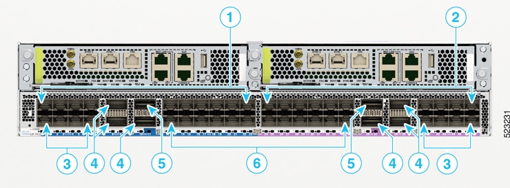
The Cisco ASR 9902 router has 48 ports that are grouped into slice 0 and slice 1. The slice 0 is color coded in blue, and slice 1 in purple:

  • 2 ports that support QSFP-DD-based 100GE pluggables

  • 6 ports that support QSFP28-based 100GE pluggables

  • 16 ports that support SFP28-based 25GE/10GE dual-rate pluggables

  • 24 ports that support SFP+- based LAN/WAN (OTN) pluggables

Figure 1. Cisco ASR 9902 Fixed Ports

1

Slice 0

4

QSFP28 ports; three on each slice.

2

Slice 1

5

QSFP-DD ports; one on each slice.

3

SFP28 ports; eight on each slice.

6

SFP+ ports; twelve on each slice.

Port Mode Configurations

The Cisco ASR 9902 router has 48 ports with maximum of 800G data bandwidth capacity. By default, these ports are in 10GE mode. You can configure the 48 ports in various port modes (100GE, 25GE, and 10GE) using the hw-module location <node> slice <number> config-mode command.

For more information, see Configuring Port Modes in Cisco ASR 9902 Router in System Management Configuration Guide for Cisco ASR 9000 Series Routers.

Cisco ASR 9903 Router Fixed Ports

The Cisco ASR 9903 Router has fixed-configuration ports that support the following transceivers:

  • 16x100GE QSFP28

  • 20x10GE SFP+

Figure 2. Cisco ASR 9903 Fixed Ports

1

QSFP28 ports (0-15)

3

QSFP28 ports

2

SFP+ ports (16-35)

4

QSFP-DD ports (0,4,8,12,16)


Note


Due to the orientation of the QSFP28 ports (20 and 21), you might not be able to disconnect fiber optic cables while the QSFP28 transceiver module is installed in the port. To disconnect fiber optic cables from the QSFP28 ports, we recommend that you first remove the QSFP28 transceiver module from the port, and then remove the cable.

Cisco ASR 9901 Router Fixed Ports

The Cisco ASR 9901 Router has 42 fixed-configuration ports that support the following transceivers:

  • 16 SFP ports

  • 24 SFP+ ports (supports SFP or SFP+)

  • 2 QSFP28 ports

Figure 3. Cisco ASR 9901 Fixed Ports

1

SFP ports (0-7)

4

SFP/SFP+ ports (22-33)

2

SFP/SFP+ ports (8-19)

5

SFP ports (34-41)

3

QSFP28 ports (20-21)


Note


Due to the orientation of the QSFP28 ports (20 and 21), you might not be able to disconnect fiber optic cables while the QSFP28 transceiver module is installed in the port. To disconnect fiber optic cables from the QSFP28 ports, we recommend that you first remove the QSFP28 transceiver module from the port, then remove the cable.

Online Insertion and Removal


Note


Installing an MPA in the Cisco ASR 9001 router will cause brief traffic interruption on the fixed ports due to the network processor (NP) initializing.

The Modular Port Adapters (MPAs) on Cisco ASR 9001 router support online insertion and removal (OIR).

Cisco ASR 9903 800G Multirate Port Expansion Card supports online insertion and removal (OIR).

Modular port adapters (MPAs) support three types of OIR(s):

  • Soft OIR

  • Managed OIR

  • Hard OIR

The 2T or 0.8T Port Expansion Cards (PECs) on the Cisco ASR 9903 chassis support managed OIR.

For more information on how to install or remove a PEC, see Install the Port Expansion Card or Remove the Port Expansion Card. To replace a PEC with another PEC, use the managed OIR procedure.

Limitation:

  • During online insertion and removal of MPA on the Cisco ASR 9001 router, the field-programmable gate array (FPGA) turns off and the physical interface (PHY) is unavailable to inhibit the clock. As a result, you will observe a SyncE jump of 80 - 120 ns on downstream nodes.

Soft OIR

Soft OIR uses the IOS XR hw-module subslot 0/0/1 reload , hw-module subslot 0/0/1 shutdown , and no hw-module subslot 0/0/1 shutdown commands to complete online insertion and removal. Refer to the Hardware Redundancy and Node Administration Commands on the Cisco ASR 9000 Series Router chapter of the Cisco ASR 9000 Series Aggregation Services Router System Management Command Reference online for command syntax.

Managed OIR

A managed online insertion and removal of Modular port adapters (MPAs) or Port Expansion Card (PEC) is comprised of these steps:

  1. Shut down the MPA or PEC with the hw-module subslot 0/0/1 shutdown command.

  2. Confirm that the LEDs have gone from green to off.

  3. Execute the do show plat command to verify that the MPA or PEC to be removed is in the disabled state.

  4. Physically remove the MPA or PEC to be replaced.

  5. Physically insert the replacement MPA or PEC.

  6. Return the MPA or PEC to the up state with the no hw-module subslot 0/0/1 shutdown command.

Hard OIR

Hard OIR is the physical online insertion and removal of Modular port adapters (MPAs) without software commands. Four types of hard OIR are supported:

  • If the bay is empty when the Cisco ASR 9001 router modular line card (MLC) boots you can do the following:

    • Insert a 20 GE MPA

    • Remove and then insert a replacement 20 GE MPA

  • If the MLC boots with a 20 GE MPA in the bay you can remove and then insert a replacement 20 GE MPA

  • If the MLC boots with a 4 10-GE MPA in the bay you can remove and then insert a replacement 4 10-GE MPA

  • If the MLC boots with a 2 10-GE MPA in the bay you can remove and then insert a replacement 2 10-GE MPA


Note


Only replacement with same types of MPA is supported by Managed OIR and Hard OIR. To replace with a different MPA type, reload the router. An empty bay during the Cisco ASR 9001 Router modular line card (MLC) bootup defaults to 20 GE MPA mode.

Cisco ASR 9001 Router Fixed Ports and Modular Port Adapters

This section describes the fixed ports and modular port adapters on the Cisco ASR 9001 Router.

Fixed 4x10-Gigabit Ethernet Ports

The Cisco ASR 9001 Router has four integrated 10 GE small form-factor pluggable (SFP+) ports that operate at a rate of 10 Gbps.

Each fixed SFP+ port has an adjacent Link LED visible on the front panel. The Link LED indicates the status of the associated SFP+ port.


Note


In Cisco ASR 9001-S Router, two 10 GE fixed SFP+ ports (SFP+2 and SFP+3) are disabled by default, and can be enabled by a license upgrade.

The following figure shows the front panel of the chassis and connectors of the fixed 4x10-Gigabit Ethernet ports.

Figure 4. 4x10-Gigabit Ethernet SFP+ Ports

1

Service LAN and ToD ports

6

External USB port

2

10MHz and 1PPS indicators

7

Eight discrete LED indicators

3

SYNC (BITS/J.211) ports

8

CLUSTER ports

4

CONSOLE and AUX ports

9

Fixed SFP+ ports

5

Management LAN ports

Modular Port Adapters

The Cisco ASR 9001 Router has two bays that support the following Modular Port Adapters (MPAs):


Note


In the Cisco ASR 9001-S Router, one bay (MPA1) is disabled by default, and can be enabled by a license upgrade.

20-Port Gigabit Ethernet Modular Port Adapter

The 20-Port Gigabit Ethernet modular port adapter provides 10 double-stacked SFP (20 total) cages that support either fiber-optic or copper Gigabit Ethernet transceivers.

Each SFP cage on the Gigabit Ethernet modular port adapter has an adjacent Link LED visible on the front panel. The Link LED indicates the status of the associated SFP port, as described in Status LEDs section.

The following figure shows an example of the 20-Port Gigabit Ethernet Modular Port Adapter.

Figure 5. 20-Port Gigabit Ethernet Modular Port Adapter

The following table describes the 20-Port Gigabit Ethernet modular port adapter LEDs.

Table 1. 20-Port Gigabit Ethernet Modular Port Adapter LEDs

LED Label

Color

State

Meaning

A/L

Off

Off

Port is not enabled.

Green

On

Port is enabled and the link is up. The MPA A/L LED will blink green when there is traffic activity.

Amber

On

Port is enabled and the link is down.

STATUS

Off

Off

Modular port adapter power is off.

Green

On

Modular port adapter is ready and operational.

Amber

On

Modular port adapter power is on and good, and modular port adapter is being configured.

4-Port 10 Gigabit Ethernet Modular Port Adapter

The 4-Port 10 Gigabit Ethernet modular port adapter provides four cages for XFP Ethernet optical interface modules that operate at a rate of 10 Gbps. The four XFP modules can be 10-Gigabit Ethernet multimode or single mode connections.

Each XFP cage on the 4-Port 10 Gigabit Ethernet modular port adapter has an adjacent Link LED visible on the front panel. The Link LED indicates the status of the associated XFP port, as described in Status LEDs section.

The following figure shows an example of the 4-Port 10 Gigabit Ethernet modular port adapter.

Figure 6. 4-Port 10 Gigabit Ethernet Modular Port Adapter

The following table describes the 4-Port 10 Gigabit Ethernet modular port adapter LEDs.

Table 2. 4-Port 10 Gigabit Ethernet Modular Port Adapter LEDs

LED Label

Color

State

Meaning

A/L

Off

Off

Port is not enabled.

Green

On

Port is enabled and the link is up. The MPA A/L LED will blink green when there is traffic activity.

Amber

On

Port is enabled and the link is down.

STATUS

Off

Off

Modular port adapter power is off.

Green

On

Modular port adapter is ready and operational.

Amber

On

Modular port adapter power is on and good, and the modular port adapter is being configured.

2-Port 10 Gigabit Ethernet Modular Port Adapter

The 2-Port 10 Gigabit Ethernet modular port adapter provides two cages for XFP Ethernet optical interface modules that operate at a rate of 10 Gbps. The two XFP modules can be 10-Gigabit Ethernet multimode or single mode connections.

Each XFP cage on the 2-Port 10 Gigabit Ethernet modular port adapter has an adjacent Link LED visible on the front panel. The Link LED indicates the status of the associated XFP port, as described in Status LEDs section.

The following figure shows an example of the 2-Port 10 Gigabit Ethernet modular port adapter.

Figure 7. 2-Port 10 Gigabit Ethernet Modular Port Adapter

The following table describes the 2-Port 10 Gigabit Ethernet modular port adapter LEDs.

Table 3. 2-Port 10 Gigabit Ethernet Modular Port Adapter LEDs

LED Label

Color

State

Meaning

A/L

Off

Off

Port is not enabled.

Green

On

Port is enabled and the link is up. The MPA A/L LED will blink green when there is traffic activity.

Amber

On

Port is enabled and the link is down.

STATUS

Off

Off

Modular port adapter power is off.

Green

On

Modular port adapter is ready and operational.

Amber

On

Modular port adapter power is on and good, and the modular port adapter is being configured.

1-Port 40 Gigabit Ethernet Modular Port Adapter

The 1-Port 40 Gigabit Ethernet modular port adapter provides a cage for a QSFP+ Ethernet optical interface module that operates at a rate of 40 Gbps.

The QSFP cage on the 1-Port 40 Gigabit Ethernet modular port adapter has an adjacent Link LED visible on the front panel. The Link LED indicates the status of the associated QSFP port, as described in Status LEDs section.

The following figure shows an example of the front panel of the 1-Port 40 Gigabit Ethernet modular port adapter.

Figure 8. 1-Port 40 Gigabit Ethernet Modular Port Adapter

1

A/L (Active/Link) LED

2

STATUS LED

The following table describes the 1-Port 40 Gigabit Ethernet modular port adapter LEDs.

Table 4. 1-Port 40 Gigabit Ethernet Modular Port Adapter LEDs

LED Label

Color

State

Meaning

A/L

Off

Off

Port is not enabled.

Green

On

Port is enabled and the link is up.

Amber

On

Port is enabled and the link is down.

STATUS

Off

Off

Modular port adapter power is off.

Green

On

Modular port adapter is ready and operational.

Amber

On

Modular port adapter power is on and good, and the modular port adapter is being configured.

Installing and Removing Modular Port Adapters

These sections describe how to install or remove modular port adapters (MPAs) on the Cisco ASR 9001 Router.

Handling Modular Port Adapters (MPAs)

Each modular port adapter (MPA) circuit board is mounted on a metal carrier, and is sensitive to electrostatic discharge (ESD) damage. Before you begin installation, refer to the Cisco ASR 9000 Series Aggregation Services Router Ethernet Line Card Installation Guide for a list of parts and tools required for installation.


Caution


Always handle the modular port adapter (MPA) by the carrier edges and handle; never touch the modular port adapter (MPA) components or connector pins. (see the following figure.)


When a bay is not in use, a blank ASR 9000 MPA Slot Filler (A9K-MPA-FILR) must fill the empty bay to allow the router to conform to electromagnetic interference (EMI) emissions requirements and to allow proper airflow across the installed modules. If you plan to install a modular port adapter (MPA) in a bay that is not in use, you must first remove the blank.

Figure 9. Handling a Modular Port Adapter (MPA)

Modular Port Adapter (MPA) Installation and Removal

This section provides step-by-step instructions for removing and installing a modular port adapter (MPA).


Caution


When performing these procedures, wear a grounding wrist strap to avoid ESD damage to the modular port adapter (MPA). Some platforms have an ESD connector for attaching the wrist strap. Do not directly touch the midplane or backplane with your hand or any metal tool, or you could shock yourself.


To remove and install a modular port adapter (MPA), perform these steps:

Procedure

Step 1

To insert the MPA, carefully slide the MPA all the way until it stops.

Note

 
The modular port adapter (MPA) will slide easily into the slot if it is properly aligned on the tracks. If MPA does not slide easily, do NOT force it. Remove the MPA and reposition it, paying close attention to engaging it on the tracks.

Step 2

To fully seat the MPA, use a number 2 Phillips screwdriver to tighten the jackscrew on the MPA.

Note

 
Avoid over torquing the modular port adapter (MPA) jackscrew when installing the MPA. Tighten the jackscrew on the MPA to a torque of 17 +/-1 inch-pound. Do not use a power screwdriver to tighten the MPA jackscrew.

Step 3

To remove the MPA, use a number 2 Phillips screwdriver to loosen the lock screw on the MPA. Make sure that the cables are disconnected from the MPA first.

Step 4

Grasp the MPA and pull the MPA from the slot.


Optical Device Installation and Removal

Any contamination of the fiber connection can cause failure of the component or failure of the whole system. A particle that partially or completely blocks the core generates strong back reflections, which can cause instability in the laser system. Inspection, cleaning, and reinspection are critical steps to take before making fiber-optic connections.

Checking the Installation

This section describes the procedures you can use to verify the modular port adapter (MPA) installation, and includes information on these topics:

Verifying the Installation

This section describes how to verify the modular port adapter (MPA) installation by observing the MPA LED states.

When the system has reinitialized all interfaces, the MPA STATUS LEDs should be on (green). The port LEDs (C/A and A/L) may be on (green), depending on your connections and configuration.

To verify that a MPA is installed correctly:

Procedure

Step 1

Observe the console display messages and verify that the system discovers the modular line card (MLC), while the system reinitializes each interface, thus:

  • As the MPA is initialized, the STATUS LED will first be amber, indicating that power is on. When the modular port adapter card (MPA) is active, the STATUS LED will illuminate green.

Step 2

When the MPA STATUS LEDs are green, all associated interfaces are configurable.

  • If a MPA is replaced with a module of the same type (as in an OIR or hardware swap), the previous configuration is reinstated when the MPA becomes active.
  • If a MPA was not previously installed in the same slot or subslot, then the configuration for all associated interfaces is empty.

Note

 
New interfaces are not made available until you configure them.

Step 3

If the modular port adapters (MPAs) do not become active within three minutes, refer to the system console messages. If there is no indication that a field-programmable device (FPD) upgrade is underway, see Troubleshooting the Installation section.


Using show Commands to Verify Modular Port Adapter (MPA) Status

This procedure uses show commands to verify that the new modular port adapters (MPAs) are configured and operating correctly.

To verify the MPA status:

Procedure

Step 1

Use the show running-config command to display the system configuration. Verify that the configuration includes the new MPA interfaces.

Step 2

Use the show diag command to display information about the installed modular line cards (MLCs).

Step 3

Use the show hw-module fpd location <rack/slot/subslot> command to verify the FPD version information of the MPAs installed in the system.

Note

 
If a modular port adapter (MPA) does not meet the minimum version required, the FPD may need to be updated. See the Cisco ASR 9000 Series Aggregation Services Router System Management Configuration Guide for instructions. If the update fails, the failing module is powered down and an error message displays on the system console

Step 4

Use the show platform command to check the state of all boards in the chassis, including the MLC and the MPAs.

The MPA state should be “OK” and the MLC state should be “IOS XR RUN” in the show platform command output.

Step 5

Use the show version command to obtain software version information for the installed MLCs as well as interfaces available.


Using show Commands to Display Modular Port Adapter (MPA) Information

The following table describes the show commands you can use to display modular port adapter (MPA) information.

Table 5. show Commands to Display Modular Port Adapter (MPA) Information

Command

Type of Information Provided

show running-config

Router’s running configuration and interfaces available in the system.

show platform

Router’s installed linecard and modular port adapter (MPA) type, slot, and state information.

show diag

Modular port adapter (MPA) type in that slot, number of ports, hardware revision, part number, and EEPROM contents.

show hw-module fpd location <rack/slot/subslot>

FPD version information of modular port adapters (MPAs) in the system.

show version

Cisco IOS XR software version, names and sources of configuration files, and boot images.

Table 6. show Commands to Display Modular Port Adapter (MPA) Information

Command

Type of Information Provided

Example

show controllers type rack/slot/subslot/port

Network link status, register contents, and controller chip errors.

show controllers GigabitEthernet 0/0/1/1

show interfaces type rack/slot/subslot/port

Line status and data link protocol status for a particular modular port adapter (MPA) port. Statistics about data traffic sent and received by the port.

show interfaces GigabitEthernet 0/0/1/1

show diag rack/slot/subslot/

Modular port adapter (MPA) type in that slot, number of ports, hardware revision, part number, and EEPROM contents.

show diag 0/0/1

show version

Cisco IOS XR software version and boot images.

show version

Using the ping Command to Verify Network Connectivity

The ping command allows you to verify whether a modular port adapter (MPA) port is functioning properly and to check the path between a specific port and connected devices at various locations on the network.

After you verify that the system and the modular line card (MLC) have booted successfully and are operational, you can use the ping command to verify the status of the MPA ports. See the Cisco ASR 9000 Series Aggregation Services Router Getting Started Guide and the Cisco ASR 9000 Series Aggregation Services Router Interface and Hardware Component Configuration Guide for more information on bringing up and configuring the Cisco ASR 9000 Series Router and the Cisco ASR 9000 A9K-MOD80G-H.

The ping command sends an echo request out to a remote device at an IP address that you specify. After sending a series of signals, the command waits a specified time for the remote device to echo the signals. Each returned signal is displayed as an exclamation point (!) on the console terminal; each signal that is not returned before the specified timeout is displayed as a period (.). A series of exclamation points (!!!!!) indicates a good connection; a series of periods (.....) or the messages [timed out] or [failed] indicate that the connection failed.

This is an example of a successful ping command to a remote server with the IP address 10.1.1.60:


Router# ping 10.1.1.60 
Type escape sequence to abort.
Sending 5, 100-byte ICMP Echoes to 10.1.1.60, timeout is 2 seconds:
!!!!!
Success rate is 100 percent (5/5), round-trip min/avg/max = 1/15/64 ms
Router#

If the connection fails, verify that you have the correct IP address for the destination device and that the destination device is active (powered on), and then repeat the ping command.

Cable Management

The Cisco ASR 9902 Router, Cisco ASR 9903 Router, Cisco ASR 9901 Router, and Cisco ASR 9001 Router includes a cable-management system that organizes the interface cables entering and exiting the router, keeping them out of the way, and free of sharp bends.


Caution


Excessive bending of interface cables can damage the cables.


The cable-management system consists of these separate components:

  • A cable-management bracket—Cisco ASR 9902, Cisco ASR 9901, and Cisco ASR 9001.

  • A cable-management bracket—Cisco ASR 9903. You can also connect a filter to the cable-management.

  • A cable-management tray—Cisco ASR 9001

Cable Management Bracket - Cisco ASR 9903 and Cisco ASR 9902 Router

A cable management bracket is attached to the rack mount bracket on the Cisco ASR 9903 and Cisco ASR 9902 Router.


Note


When shipped, the cable management bracket is not attached to the router chassis. Attach the cable-management bracket to the chassis before you insert the cables into the ports.


Installing a Cable Management Bracket

To install a cable-management bracket, follow these steps:

This procedure is applicable for Cisco ASR 9903 and Cisco ASR 9902 Routers.

Procedure

Step 1

Attach an ESD-preventive wrist or ankle strap, and follow its instructions for use.

Step 2

Position the cable management bracket over the center holes of the chassis rack mount brackets. See the following figure.

Figure 10. Cable-Management Bracket Installation and Removal-Cisco ASR 9903 Router
Figure 11. Cable-Management Bracket Installation and Removal-Cisco ASR 9902 Router

Step 3

Insert and tighten the provided screws to secure the bracket.

Step 4

Install pluggables and fiber connectors, and connect all the cables to the intended ports.

Step 5

Attach cables and fibers to the cable management bracket in an organized manner.

Caution


Ensure the interface cables do not have any kinks or sharp bends. This can destroy or degrade the ability of the optical fiber to propagate the signal-encoded beam of light accurately from one end of the cable to the other. Always allow adequate strain relief for the interface cable.

Step 6

Install the air filter if required. See Removing and Replacing the Air Filter for Cisco ASR 9903 and Cisco ASR 9902


Removing a Cable-Management Bracket

To remove a cable-management bracket, follow these steps:

This procedure is applicable for Cisco ASR 9903 and Cisco ASR 9902 Routers.

Procedure

Step 1

Attach an ESD-preventive wrist or ankle strap, and follow its instructions for use.

Step 2

Remove the air filter if installed. See Removing and Replacing the Air Filter for Cisco ASR 9903 and Cisco ASR 9902

Step 3

Note the current interface cable connections to the ports on the RP.

Step 4

Starting with the interface cable for the bottom port on the RP, disconnect the cable from the RP interface.

Step 5

Repeat Step 4 for all remaining interface cables, proceeding upwards from the bottom ports.

Step 6

Loosen the installation screws on each end of the cable-management bracket, and remove the bracket from the chassis.


Cable Management Bracket—Cisco ASR 9901

A cable management bracket is attached to the rack mount bracket on the Cisco ASR 9901 Router.

Figure 12. Cisco ASR 9901 Router Cable Management Bracket

Note


When shipped, the cable-management bracket is not attached to the router chassis. You must attach the cable-management bracket to the chassis before you insert the cables into the ports.

Installing a Cable Management Bracket

To install a cable-management bracket, follow these steps:

Procedure

Step 1

Attach an ESD-preventive wrist or ankle strap and follow its instructions for use.

Step 2

Position the cable management bracket over the center holes of the chassis rack mount brackets (see the following figure).

Figure 13. Cable-Management Bracket Installation and Removal

Step 3

Insert and tighten the provided screws to secure the bracket.

Step 4

Install pluggables and fiber connectors, and connect all the cables to intended ports.

Step 5

Attach cables and fibers to the cable management bracket in an organized manner.

Caution

 
Make sure the interface cables do not have any kinks or sharp bends, which can destroy or degrade the ability of the optical fiber to propagate the signal-encoded beam of light accurately from one end of the cable to the other. Always allow adequate strain relief in the interface cable.

Removing a Cable-Management Bracket

To remove a cable-management bracket, follow these steps:

Procedure

Step 1

Attach an ESD-preventive wrist or ankle strap and follow its instructions for use.

Step 2

Note the current interface cable connections to the ports on the RP.

Step 3

Starting with the interface cable for the bottom port on the RP, disconnect the cable from the RP interface.

Step 4

Repeat Step 3 for all remaining interface cables, proceeding from the bottom ports upward, then proceed to Step 5.

Step 5

Loosen the installation screws on each end of the cable-management bracket and remove the bracket from the chassis (see the above figure).


Cable Management Bracket—Cisco ASR 9001

The Cisco ASR 9001 Router provides a cable management bracket at the middle of the router chassis. The following figure shows a typical cable routing for the Cisco ASR 9001 Router.

Figure 14. Example Cable Routing through Cisco ASR 9001 Router Cable Management Brackets

Note


When shipped, the cable-management bracket is not attached to the router chassis. You must attach the cable-management bracket to the chassis before you insert the cables into the ports.

Installing a Cable Management Bracket

To install a cable-management bracket, follow these steps:

Procedure

Step 1

Attach an ESD-preventive wrist or ankle strap and follow its instructions for use.

Step 2

Position the cable-management bracket over the front of the chassis front panel.

Figure 15. Cable-Management Bracket Installation and Removal

1

Cable-Management Bracket

Step 3

Insert and tighten the captive screw(s) to secure the bracket.

Step 4

Connect all the cables to the intended ports and pass them through the cable management bracket in an organized manner.


Removing a Cable-Management Bracket

To remove a cable-management bracket, follow these steps:

Procedure

Step 1

Attach an ESD-preventive wrist or ankle strap and follow its instructions for use.

Step 2

Note the current interface cable connections to the ports on the RP.

Step 3

Starting with the interface cable for the bottom port on the RP, disconnect the cable from the RP interface.

Step 4

Repeat Step 3 for all remaining interface cables, proceeding from the bottom ports upward, then proceed to Step 5.

Step 5

Loosen the captive installation screw on the cable-management bracket and remove the bracket from the chassis (see the above figure).


Cable Management Tray—Cisco ASR 9001

A cable-management tray is mounted at the bottom of the Cisco ASR 9001 Router chassis for routing interface cables to the RP. The following figure shows a typical cable routing through the cable-management tray.

Figure 16. Example Cable Routing through the Cisco ASR 9001 Router Cable Management Tray

Installing a Cable Management Tray

To install a cable-management tray, follow these steps:

Procedure

Step 1

Attach an ESD-preventive wrist or ankle strap and follow its instructions for use.

Step 2

Position the cable-management tray at the bottom of the chassis front panel.

Figure 17. Cable-Management Tray Installation and Removal
  1. Cable-Management Tray

Step 3

Insert and tighten the captive screw(s) to secure the tray.

Step 4

Connect all the cables to the intended ports and pass them through the cable management tray in an organized manner.


Removing a Cable-Management Tray

To remove a cable-management tray, follow these steps:

Procedure

Step 1

Attach an ESD-preventive wrist or ankle strap and follow its instructions for use.

Step 2

Note the current interface cable connections to the ports on the RP.

Step 3

Starting with the interface cable for the bottom port on the RP, disconnect the cable from the RP interface.

Step 4

Repeat Step 3 for all remaining interface cables, proceeding from the bottom ports upward, then proceed to Step 5.

Step 5

Loosen the captive installation screw on the cable-management tray and remove the tray from the chassis (see the above figure).


Connecting Route Processor Cables

This section describes how to connect cables to the console, auxiliary, and Ethernet ports on the RP. The console and auxiliary ports are both asynchronous serial ports; any devices connected to these ports must be capable of asynchronous transmission. Most modems are asynchronous devices.

The following figure shows an example of an RP with data terminal and modem connections called out.

Figure 18. RP Console and Auxiliary Port Connections

1

Console terminal

3

RJ-45 cables

2

Modem

4

Console and Auxiliary port


Caution


The ports labeled Ethernet, Console, and AUX are safety extra-low voltage (SELV) circuits. SELV circuits should only be connected to other SELV circuits.

Note


RP cables are not available from Cisco, but they are available from external commercial cable vendors.

Note


To comply with the intra-building lightning surge requirements of Telecordia GR-1089-CORE, Issue 6, you must use a shielded cable when connecting to the Ethernet ports. The shielded cable is terminated by shielded connectors on both ends, with the cable shield material tied to both connectors.

Connecting to the RP Console Port

The system console port on the RP is an RJ-45 receptacle for connecting a data terminal to perform the initial configuration of the router. Depending on the cabling pinout on the terminal server end, the console port will require either a crossover cable or a straight-through RJ-45 cable. See Port Connection Guidelines for additional information about the console port.

See the previous and follow these steps to connect a data terminal to the RP console port:

Procedure


Step 1

Set your terminal to these operational values: 115200 bps, 8 data bits, no parity, 1 stop bits (115200 8N1).

Step 2

Attach the terminal end of the cable to the interface port on the data terminal.

Step 3

Attach the other end of the cable to the RP console port.

Step 4

Power on the data terminal.


Connecting to the RP Auxiliary Port

The auxiliary port on the RP is a RJ-45 receptacle for connecting a modem or other data communication equipment (DCE) device (such as another router) to the RP. The asynchronous auxiliary port supports hardware flow control and modem control. See Port Connection Guidelines for additional information about the auxiliary port.

See the previous figure and follow these steps to connect an asynchronous serial device to the RP auxiliary port:

Procedure


Step 1

Power off the asynchronous serial device.

Step 2

Attach the device end of the cable to the interface port on the asynchronous serial device.

Step 3

Attach the other end of the cable to the RP auxiliary port.

Step 4

Power on the asynchronous serial device.


Connecting to the RP Ethernet Management Ports

To connect cables to the RP management ports, attach STP (Shielded Twisted Pair) cables directly to the MGT LAN 0 and MGT LAN 1 RJ-45 receptacles on the RP. STP cables are required to meet NEBS requirements. See Management LAN Ports Connection Guidelines for additional information about the Ethernet management LAN ports.


Note


RJ-45 cables are not available from Cisco Systems; they are available from external commercial cable vendors. Use cables that comply with EIA/TIA-568 standards.

Caution


Ethernet management ports are primarily used as Telnet ports into the Cisco ASR 9001, and for booting or accessing Cisco software images over a network to which an Ethernet port is directly connected. We strongly caution you to consider the security implications of enabling routing functions on these ports.


Note


The Ethernet interfaces on the RP are end-station devices only, not repeaters.

Use this procedure to connect an Ethernet cable to the RP RJ-45 Ethernet receptacle:

Procedure


Step 1

Plug the cable directly into the RJ-45 receptacle.

Step 2

Connect the network end of your RJ-45 cable to a switch, hub, repeater, or other external equipment.


Installing Route Processor Cards into the Cisco ASR 9903 and Cisco ASR 9902 Chassis

This section describes how to install the Route Processor (RP) cards into the Cisco ASR 9903 and Cisco ASR 9902 chassis.

Figure 19. Ejector Parts

1

Lever

2

Catch

3

Handle

Prerequisite: After removing the RP card from its packaging, check for any damage and check whether the ejector has any bend.

  1. Pull the ejector by sliding the catch towards your right using your thumb. The ejector handle starts rotating.

  2. Pull the ejector handle until it stops rotating.
    Figure 20. Slide the Catch Towards the Right-Side and Pull the Ejector
  3. Insert the RP card into chassis with ejector in a fully-open position.
    Figure 21. Insert RP Card into the Chassis
    When you push the RP card further inside, the ejector meets the chassis as shown in the following figure:
    Figure 22. Ejector Meets the Chassis
  4. In the condition when the ejector meets the chassis, slowly rotate the ejector so that it grabs the chassis, and push the RP card further into the chassis.

    Note


    Operate the ejector only by pushing the handle. Ensure the catch is fully moved and seated in its correct position.


    Figure 23. Push the Handle
  5. Tighten the captive screws fully to secure the RP inside the chassis.
    Figure 24. Tighten the Captive Screws

Removing the Route Processor Card from the Cisco ASR 9903 and Cisco ASR 9902 Chassis

This section describes how to remove the RP cards from the Cisco ASR 9903 and Cisco ASR 9902 chassis.

  1. Unscrew the captive screws.
    Figure 25. Unscrew the Captive Screw
  2. Push the catch towards your right using thumb and pull the handle of the ejector.

    The RP card slowly comes out of the chassis.

    Figure 26. Pull Ejector Handle
  3. Pull the handle until the ejector stops rotating and take the RP card out from the chassis.
    Figure 27. Take RP Card Out

ASR 9903 Port Expansion Cards

The Cisco ASR 9903 router supports an optional 2T or 0.8T Port Expansion Card (PEC). These PECs are removable modules, and you can install a new PEC, replace a PEC, or remove a PEC in your router.

Here are some of the scenarios when you'd perform the installation, replacement, or removal of the PECs:

800G or 0.8T Port Expansion Card

Table 7. Feature History Table

Hardware

Release Information

Description

Online Insertion and Removal Support on Cisco ASR 9903 Series 800G Port Expansion Card

Release 7.8.1

From this release, you can perform the Online Insertion and Removal (OIR) of the Cisco ASR 9903 Series 800G Port Expansion Card (A9903-8HG-PEC or 0.8T PEC). OIR enables users to replace a defective module without interrupting router operations. It is now possible to replace the 0.8T PEC in the Cisco ASR 9903 router without any traffic disruption.

For more information on:

The Cisco A9903-8HG-PEC is an optional removable module that offers 48 physical ports with maximum 800G data bandwidth capacity. Here are few physical features of this module:

  • It offers two sets of port combinations:

    • forty-eight 10GE SFP+

    • thirty-two 25GE SFP28 ports

  • The ports are grouped in slice 4 and slice 5. These slices are marked in blue and purple as shown in the following image.


    Note


    A slice is a logical grouping of physical ports.


  • You can configure both slices in:

    • 10GE mode or 25GE mode. For example, slice 4 and slice 5 in 25GE mode.

    • a mix of 10GE and 25GE mode. For example, slice 4 in 10GE and slice 5 in 25GE mode.

  • By default, all 48 ports are in 10GE mode. To change the port-mode to 25GE mode, use hw-module location <node> slice <number> config-mode command. For more information, see Configuring Port Modes in 0.8T PEC.

  • It supports line-rate MACSec on 10GE and 25GE.

Figure 28. Cisco ASR 9903 Series 800G Port Expansion Card – Port Layout
Figure 29. Cisco ASR 9903 Series 800G Port Expansion Card – Top View

2T Port Expansion Card

  • The 2T Port Expansion Card has five 400GE QSFP-DD ports and fifteen 100GE QSFP28 ports.

  • The 2T PEC can provide up to 2-Tbps throughput.

  • You can group the ports into five groups of four ports each. Each group includes one QSFP-DD port and three QSFP28 ports. You can configure the QSFP-DD port with 400GE port rate in which case the other three physical ports in that port group are unused.

  • Each QSFP28 port is capable of supporting 100GE and 40GE. It can also breakout into a 4x25GE or 4x10GE.

  • All of the QSFP-DD and QSFP28 physical ports support 1x100GE, 1x40GE, 4x25GE, and 4x10GE.

Figure 30. ASR 9903 2T Port Expansion Card – Port Layout
Figure 31. ASR 9903 2T Port Expansion Card – Top View

Note


You cannot insert line cards from other ASR 9000 Series Routers into the Cisco ASR 9903 chassis.


Install the Port Expansion Card

This section describes how to install the 2T or 0.8T PEC into the Cisco ASR 9903 chassis.


Note


Conduct a visual inspection of back plane connectors.

Note


  • From Release 7.8.1 onwards, support for managed OIR is introduced on 0.8T PEC(A9903-8HG-PEC).

  • From Release 7.3.2 onwards, support for managed OIR is introduced on 2T PEC(A9903-20HG-PEC).

For more information on managed OIR, see Online Insertion and Removal.
  1. Shut down the line card (LC0) using the hw-module shutdown location command from EXEC mode.

  2. Gently insert the PEC into the chassis in proper orientation.

    Figure 32. Install PEC into Chassis

    1

    Port expansion card slot on the chassis

    2

    Alignment guide on the PEC

    3

    Ejector handle

  3. Use the ejector handle to leverage final seating of connectors and then lock the ejector handle.

  4. Tighten the card securing screws on both ends with the torque of 0.6 N-m.


    Note


    • If you do not completely tighten the screws, the card will not power ON.

    • Do not exceed the torque value while tightening the screws to prevent damage.


  5. Reload the router using the hw-module location all reload command in admin mode.

  6. Wait for the status LED to turn from blinking amber color to green color.

Remove the Port Expansion Card

This section describes how to remove the 2T or 0.8T PEC from the Cisco ASR 9903 chassis.


Note


  • From Release 7.8.1 onwards, support for managed OIR is introduced on 0.8T PEC(A9903-8HG-PEC).

  • From Release 7.3.2 onwards, support for managed OIR is introduced on 2T PEC(A9903-20HG-PEC).


  1. Shut down the line card (LC0) using the hw-module shutdown location command from EXEC mode.

  2. Unscrew port expansion card securing screws on either ends, one after the other.

  3. Wait for the status LED to turn from green color to red color.

  4. Unlatch ejector handle and use it as a lever to carefully eject the card.

    Figure 33. Remove PEC from Chassis

    1

    Ejector handle

  5. Gently pull the card out of the chassis.

  6. Inspect the backplane connectors for any signs of damage.

  7. Reload the router using the hw-module location all reload command in admin mode.

Connecting Power to the Router

Use one of these procedures to connect power to your router.


Note


On the Cisco ASR 9902 router you must first install the PSUs and then follow any of the below procedures to connect power to the router


Caution


A router must be operated with all its power modules installed at all times for electromagnetic compatibility (EMC).


Connecting Power to an AC-Powered Router

Use this procedure to connect the AC power cords to the router.


Note


Connect each AC power supply to a dedicated power source (branch circuit). Each AC-input power supply operates at a nominal input level of 100 to 240 VAC and requires at least a 15 A service for use in North America and Japan, or a 10 A service for international use. For more information on AC power input levels, see Power Connection Guidelines.

Procedure


Step 1

Check that the power switch at the front (or at the rear for Cisco ASR 9902) of the chassis is set to the OFF position.

Step 2

Check that the circuit breaker assigned to the AC power source you are connecting is set to OFF.

Step 3

Connect the permanent ground connection (central office grounding system) to the NEBS grounding location on the router chassis.

Note

 
To ensure that power remains off while you are performing this procedure, turn the circuit breaker switch in the off (0) position until you are ready to turn it on.

Step 4

Do one of the following:

  • Cisco ASR 9903: Plug the AC power cord into the receptacle at the rear of the chassis (see the following figure).
  • Cisco ASR 9901: Plug the AC power cord into the receptacle at the rear of the chassis (see the following figure).

  • Cisco ASR 9001: Plug the AC power cord into the receptacle at the front of the chassis (see the following figure).

Step 5

Close the cable wrap to secure the AC power cord plug to the power module receptacle.

Step 6

Plug the other end of the AC power cord into the AC source receptacle.

Step 7

Proceed to Powering on the Router.


Connecting Power to a DC-Powered Router

This section contains the procedures to connect the DC source power cables to a DC-powered router.

The color coding of source DC power cable leads depends on the color coding of the site DC power source. Because there is no color code standard for source DC wiring, you must be sure that power source cables are connected to the power module with the proper positive (+) and negative (–) polarity:

  • In some cases, the source DC cable leads might have a positive (+) or a negative (–) label. This is a relatively safe indication of the polarity, but you must verify the polarity by measuring the voltage between the DC cable leads . Be sure that the positive (+) and negative (–) cable leads match the positive (+) and negative (–) labels on the power module when making the measurement.

  • Green (or green and yellow) cable typically indicates that it is a ground cable.


Caution


DC power modules contain reverse voltage protection circuitry to prevent damage to the module if it detects a reverse polarity condition. No damage should occur from reverse polarity, but you should correct a reverse-polarity condition immediately.

Note


The length of the cables depends on the location of your router in relation to the source of DC power. These cables are not available from Cisco Systems. They are available from external commercial cable vendors. For more information on site power and source DC cable requirements, see Power Connection Guidelines.

Note


To ensure that power remains off while you are performing this procedure, follow proper lockout /tagout procedures as defined by your company in accordance with local and national laws.

Use this procedure to connect the DC source power cables to a DC power module:

Procedure


Step 1

Verify that the power switch is set to the OFF position.

Step 2

Connect the DC power cables in the following order (see the figure below):

  1. Positive cables first.

  2. Negative cable last.

Step 3

Repeat Step 2 for the other power modules installed in the chassis.

Caution

 
To prevent injury and damage to the equipment, always attach the ground and source DC power cable to power module terminals in the following order: (1) ground to ground, (2) positive (+) to positive (+), (3) negative (–) to negative (–).
Figure 34. Cisco ASR 9901: Typical Power Connections for a Single DC Power Module
Figure 35. Cisco ASR 9001: Typical Power Connections for a Single DC Power Module

Step 4

Proceed to the next section.


Powering on the Router


Note


This equipment is designed to boot up in less than 30 minutes, depending on its neighboring devices be fully up and running.

Follow these steps to turn on power to either an AC-powered or DC-powered router:

Procedure


Step 1

Switch on the circuit breaker to your power sources.

Step 2

Set the power switch to the ON position. The chassis power LED turns Red.

  • Figure 36. Power Switch on the Cisco ASR 9902 Router

    1

    Power Switch

    2

    Power Status

  • Figure 37. Power Switch on the Cisco ASR 9903

    Note


    There is no power switch available on the AC and DC PSUs for the Cisco ASR 9903 routers as they are plug-and-play devices. The power LED is available on the front-side of the router.

  • Figure 38. Power Switch on the Cisco ASR 9901
  • Figure 39. Power Switch on the Cisco ASR 9001

Step 3

Verify that the Power LED on each power module is lit Green.