Prepare for Installation

This chapter provides preinstallation information, such as recommendations and requirements that must be met before installing your router. Before you begin, inspect all items for shipping damage. If anything appears to be damaged or if you encounter problems installing or configuring your router, contact customer service.


Note


The images in this chapter are only for representational purposes, unless specified otherwise. The chassis' actual appearance and size may vary.

Standard Warning Statements

This section describes the warning definition and then lists core safety warnings grouped by topic.


Warning


Statement 1071—Warning Definition

IMPORTANT SAFETY INSTRUCTIONS

Before you work on any equipment, be aware of the hazards involved with electrical circuitry and be familiar with standard practices for preventing accidents. Read the installation instructions before using, installing, or connecting the system to the power source. Use the statement number at the beginning of each warning statement to locate its translation in the translated safety warnings for this device.

SAVE THESE INSTRUCTIONS


General Safety Warnings


Warning


Statement 1089—Instructed and Skilled Person Definitions

An instructed person is someone who has been instructed and trained by a skilled person and takes the necessary precautions when working with equipment.

A skilled person or qualified personnel is someone who has training or experience in the equipment technology and understands potential hazards when working with equipment.

There are no serviceable parts inside. To avoid risk of electric shock, do not open.


Warning


Statement 9001—Product Disposal

Ultimate disposal of this product should be handled according to all national laws and regulations.


Warning


Statement 1073—No User-Serviceable Parts

There are no serviceable parts inside. To avoid risk of electric shock, do not open.


Warning


Statement 1074—Comply with Local and National Electrical Codes

To reduce risk of electric shock or fire, installation of the equipment must comply with local and national electrical codes.


Note


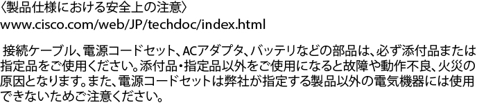
Statement 407—Japanese Safety Instruction

You are strongly advised to read the safety instruction before using the product.

https://www.cisco.com/web/JP/techdoc/pldoc/pldoc.html

When installing the product, use the provided or designated connection cables/power cables/AC adapters.


Warning


Statement 1090—Installation by Skilled Person

Only a skilled person should be allowed to install, replace, or service this equipment. See statement 1089 for the definition of a skilled person.

There are no serviceable parts inside. To avoid risk of electric shock, do not open.


Warning


Statement 1091—Installation by an Instructed Person

Only an instructed person or skilled person should be allowed to install, replace, or service this equipment. See statement 1089 for the definition of an instructed or skilled person.

There are no serviceable parts inside. To avoid risk of electric shock, do not open.


Warning


Statement 1029—Blank Faceplates and Cover Panels

Blank faceplates and cover panels serve three important functions: they reduce the risk of electric shock and fire, they contain electromagnetic interference (EMI) that might disrupt other equipment, and they direct the flow of cooling air through the chassis. Do not operate the system unless all cards, faceplates, front covers, and rear covers are in place.


Warning


Statement 1015—Battery Handling

To reduce risk of fire, explosion, or leakage of flammable liquid or gas:

  • Replace the battery only with the same or equivalent type recommended by the manufacturer.

  • Do not dismantle, crush, puncture, use a sharp tool to remove, short the external contacts, or dispose of the battery in fire.

  • Do not use if battery is warped or swollen.

  • Do not store or use battery in a temperature > .

  • Do not store or use battery in low air pressure environment < .


Safety Guidelines

Before you perform any procedure in this document, review the safety guidelines in this section to avoid injuring yourself or damaging the equipment. The following guidelines are for your safety and to protect the equipment. Because the guidelines do not include all hazards, be constantly alert.

  • Keep the work area clear, smoke and dust-free during and after installation. Do not allow dirt or debris to enter into any laser-based components.

  • Do not wear loose clothing, jewelry, or other items that could get caught in the router or other associated components.

  • Cisco equipment operates safely when used in accordance with its specifications and product-usage instructions.

  • If potentially hazardous conditions exist, do not work alone.

  • Take care when connecting multiple units to the supply circuit so that wiring is not overloaded.

  • This equipment must be grounded. Never defeat the ground conductor or operate the equipment in the absence of a suitably installed ground conductor. Contact the appropriate electrical inspection authority or an electrician if you are uncertain about whether suitable grounding is available.

  • When installing or replacing the unit, the ground connection must always be made first and disconnected last.

  • To prevent personal injury or damage to the chassis, never attempt to lift or tilt the chassis using the handles on modules (such as power supplies, fans, or cards); these types of handles are not designed to support the weight of the unit.

  • Hazardous voltage or energy is present on the backplane when the system is operating. Use caution when servicing.

Laser Safety


Warning


Statement 1051—Laser Radiation

Invisible laser radiation may be emitted from disconnected fibers or connectors. Do not stare into beams or view directly with optical instruments.


Warning


Statement 1055—Class 1/1M Laser

Invisible laser radiation is present. Do not expose to users of telescopic optics. This applies to Class 1/1M laser products.


Warning


Statement 1255—Laser Compliance Statement

Pluggable optical modules comply with IEC 60825-1 Ed. 3 and 21 CFR 1040.10 and 1040.11 with or without exception for conformance with IEC 60825-1 Ed. 3 as described in Laser Notice No. 56, dated May 8, 2019.


Energy Hazard

The routers can be configured for a DC power source. Do not touch terminals while they are live. Observe the following warning to prevent injury.


Warning


Statement 1086—Replace Cover on Power Terminals

Hazardous voltage or energy may be present on power terminals. To reduce the risk of electric shock, make sure the power terminal cover is in place when the power terminal is not being serviced. Be sure uninsulated conductors are not accessible when the cover is in place.


Preventing Electrostatic Discharge Damage

Many router components can be damaged by static electricity. Not exercising the proper electrostatic discharge (ESD) precautions can result in intermittent or complete component failures. To minimize the potential for ESD damage, always use an ESD-preventive antistatic wrist strap (or ankle strap) and ensure that it makes adequate skin contact.


Note


Check the resistance value of the ESD-preventive strap periodically. The measurement should be 1–10 megohms.

Before you perform any of the procedures in this guide, attach an ESD-preventive strap to your wrist and connect the leash to the chassis.

Cautions and Regulatory Compliance Statements for NEBS

The NEBS-GR-1089-CORE regulatory compliance statements and requirements are discussed in this section.


Warning


The intrabuilding port(s) of the equipment or subassembly, which is the management Ethernet port, must use shielded intrabuilding cabling/wiring that is grounded at both ends. Statement 7003

Warning


The intrabuilding port(s) of the equipment or subassembly, which is the management Ethernet port, must not be metallically connected to interfaces that connect to the OSP or its wiring. These interfaces are designed for use as intrabuilding interfaces only (Type 2 or Type 4 ports as described in GR-1089-CORE) and require isolation from the exposed OSP cabling. The addition of Primary Protectors is not sufficient protection in order to connect these interfaces metallically to OSP wiring. Statement 7005

Warning


This equipment shall be connected to AC mains provided with a surge protective device (SPD) at the service equipment complying with NFPA 70, the National Electrical Code (NEC). Statement 7012

Warning


This equipment is suitable for installations utilizing the Common Bonding Network (CBN). Statement 7013

Warning


The battery return conductor of this equipment shall be treated as (DC-I). Statement 7016

Warning


This equipment is suitable for installation in Network Telecommunications Facilities. Statement 8015

Warning


This equipment is suitable for installation in locations where the NEC applies. Statement 8016

Installation Guidelines

Before installing the chassis, ensure that the following guidelines are met:

  • Site is properly prepared so that there is sufficient room for installation and maintenance.

  • Operating environment is within the ranges that are listed in Environment and Physical specifications. For more details on environmental requirements, see Cisco 8608 Router Data Sheet.

  • Chassis is mounted at the bottom of the rack if it is the only unit in the rack.

  • When mounting the chassis in a partially filled rack, load the rack from the bottom to the top with the heaviest component at the bottom of the rack.

  • If the rack is provided with stabilizing devices, install the stabilizers before mounting or servicing the chassis in the rack.

  • Airflow around the chassis and through the vents is unrestricted.

  • Cabling is away from sources of electrical noise, such as radios, power lines, and fluorescent lighting fixtures. Make sure that the cabling is safely away from other devices that might damage the cables.

  • Each port must match the wave-length specifications on each end of the cable, and the cable must not exceed the stipulated cable length.


Note


Cisco 8000 Series Routers function in operating temperatures of up to 40°C at sea level. For every 300 meters (1000 ft) elevation upto 1800 meters (6000 ft), the maximum temperature is reduced by 1°C. For more details on environmental requirements, see Cisco 8608 Router Data Sheet.


Procure Tools and Equipment

Obtain these necessary tools and equipment for installing the chassis:

  • Number 1 and number 2 Phillips screwdrivers with torque capability to rack-mount the chassis.

  • 3/16-inch flat-blade screwdriver.

  • Tape measure and level.

  • ESD wrist strap or other grounding device.

  • Antistatic mat or antistatic foam.

  • Two-hole ground lug (1).

  • A crimping tool specified by the lug manufacturer that is large enough to accommodate the girth of the lug.

  • Wire-stripping tool.

Router Accessory Kits

Router Accessory Kit

The accessory kits for the Cisco 8608 fixed port router includes the following:

Table 1. Router Accessory Kits
Kit Name Description Quantity

Ground lug kit

90 degree lug

1

M4 x 6-mmPhillips flat-head screws

2

Rack mount kit (8608-RMBRKT)

Rack-mount brackets

8

M4 x 6-mmPhillips flat-head screws

20

Door kit (8608-DRKT)

Door frame

2

M4 x 6 mm pan-head Phillips screws

9


Note


If you purchased this product through a Cisco reseller, you might receive more contents in your kit, such as documentation, hardware, and power cables.

The shipped cables depend on your specification when placing an order. See the Power Supply Power Cord Specifications section for information on the available power cords.


Discrepancies or Damage?

If you notice any discrepancies or damage, send the following information to your customer service representative by email:

  • Invoice number of the shipper (see the packing slip)

  • Model and serial number of the missing or damaged unit

  • Description of the problem and how it affects the installation

  • Photos of the damage to external packaging, internal packaging, and product

Prepare Your Location

This section illustrates how the building that houses the chassis must be properly grounded to the earth ground.


Note


Unless specified otherwise, the image is only for representational purposes. The rack's actual appearance and size may vary.

Note


This image is only for representational purposes. Your grounding requirement depends on your building.
Figure 1. Building with Rack Room Connected to Earth Ground

Prepare Yourself

This section illustrates how to prepare yourself before removing the chassis from the sealed antistatic bag. The figures show how to cuff the ESD strap around the wrist and the ground cord that connects the cuff to the ground. ESD wrist straps are the primary means of controlling static charge on personnel.

Figure 2. Wearing the ESD Strap

Prepare Rack for Chassis Installation

Install the Cisco 8600 Series Routers on a standard 19 inch, Electronic Industries Alliance (EIA) rack with mounting rails that conform to English universal hole spacing according to Section 1 of the ANSI/EIA-310-D-1992 standard.


Note


The Cisco 8600 router rack mount kit contains the rack mounting brackets for 19-inch rack.


The spacing between the posts of the rack must be (EIA-310-D-1992 19-inch rack compatible) wide enough to accommodate the width of the chassis.

Figure 3. Rack Specification EIA (19 inches)
Table 2. Rack Specification EIA (19 inches)

Post Type

Rack Type

Rack Front Opening (X)

Rack Mounting Hole Center-Center (Y)

Mounting Flange Dimension (Z)

4 Post

19 inches (48.3 centimeters)

450.8mm (17.75”)

465mm (18.312”)

482.6mm (19”)

4 Post

23 inches (58.4 centimeters)

552.45mm (21.75”)

566.7mm (22.312”)

584.2mm (23”)

Before you move the chassis or mount the chassis into the rack, we recommend that you do the following:

Procedure


Step 1

Place the rack at the location where you plan to install the chassis.

Step 2

(Optional) Secure the rack to the floor.

To bolt the rack to the floor, a floor bolt kit (also called an anchor embedment kit) is required. For information on bolting the rack to the floor, consult a company that specializes in floor mounting kits (such as Hilti; see Hilti.com for details). Make sure that floor mounting bolts are accessible, especially if annual retorquing of bolts is required.

Note


Ensure that the rack in which the chassis is being installed is grounded to earth ground.


Clearance Requirements

To ensure adequate airflow, we recommended that you maintain a minimum of 6 in. (15.24 cm) front and rear clearance for air intake/exhaust.

If the router is installed in a perforated door cabinet, maintain a minimum of 6 in. (15.24 cm) from the inside of the door. The front and rear doors of the cabinet must be perforated with a minimum open area of 70%.

Following figure shows the clearances required for installation of Cisco 8600 Series Routers.

Figure 4. Clearances Required Around the Chassis

1

Chassis

4

Clearance required in rear of the chassis for air exhaust

2

Clearance required in front of the chassis for air intake

5

Rear service area for the fan tray and switch card replacement

3

Chassis depth