Installing the Chassis

Rack Mount the Chassis

The chassis can be mounted on a 4-post rack.


Warning


Statement 1032—Lifting the Chassis

To prevent personal injury or damage to the chassis, never attempt to lift or tilt the chassis using the handles on modules, such as power supplies, fans, or cards. These types of handles are not designed to support the weight of the unit.


Warning


Statement 1006—Chassis Warning for Rack-Mounting and Servicing

To prevent bodily injury when mounting or servicing this unit in a rack, you must take special precautions to ensure that the system remains stable. The following guidelines are provided to ensure your safety:

  • This unit should be mounted at the bottom of the rack if it is the only unit in the rack.

  • When mounting this unit in a partially filled rack, load the rack from the bottom to the top with the heaviest component at the bottom of the rack.

  • If the rack is provided with stabilizing devices, install the stabilizers before mounting or servicing the unit in the rack.


Rack-Mount the Chassis in a 4-Post Rack

This section describes how to install the router in a 4-post rack.


Caution


If the rack is on wheels, ensure that the brakes are engaged or that the rack is otherwise stabilized.

The following table lists the items that are contained in the rack-mount kit.

Table 1. Rack-Mount Kit

Quantity

Part Description

2

Rack-mount brackets

18

M4 x 6-mm Phillips flat-head screws

2

M4 x 6-mm Phillips pan-head screws

2

Rack-mount guides

2

Rack-mount guide rails, 2 lengths for different 4-post depths

1

Grounding plate (applies to Cisco 8201, Cisco 8201-32FH, and Cisco 8201-24H8FH routers)

1

Grounding lug and screws

Procedure


Step 1

Install the rack-mount brackets to the router as follows:

  1. Determine which end of the chassis is to be located in the cold aisle as follows:

    • If the router has port-side intake modules (fan modules and power modules with burgundy coloring), position the router so that the ports are in the cold aisle.

    • If the router has port-side exhaust modules (fan modules and power modules with blue coloring), position the router so that the fan and power supply modules are in the cold aisle.

  2. (Only Cisco 8201, Cisco 8201-32FH, and Cisco 8201-24H8FH ) Attach the grounding plate to the chassis. Use two M4 flat-head screws with 13.25 in-lbs (1.5 N-m) torque value to attach the grounding plate to the chassis.

    Note


    The Cisco 8201 chassis has a grounding cover label that must be removed before attaching the grounding plate to the chassis.

  3. Position a rack-mount bracket on the side of the chassis with its four holes that are aligned to four of the screw holes on the side of the chassis, and then use four M4 flat-head screws with 13.25 in-lbs (1.5 N-m) torque value to attach the bracket to the chassis.

    Note

     
    You can align four holes in the rack-mount bracket to four screw holes on the front side of chassis or four screw holes on the rear side of the chassis. The holes that you use depend on which end of your chassis is located in the cold aisle.
    Figure 1. Rack-Mount Brackets on Cisco 8201 Router—Port-Side Intake
    Figure 2. Rack-Mount Brackets on Cisco 8201 Router—Port-Side Exhaust

    1

    Rack-mount brackets

    4

    Rack-mount guide rails

    2

    M4 x 6mm Phillips flat-head screws

    5

    Remove grounding cover label

    3

    Rack-mount guide

    6

    Grounding plate

    Figure 3. Rack-Mount Brackets (8K-2RU-KIT-S) on Cisco 8202-32FH-M Router—Port-Side Intake
    Figure 4. Rack-Mount Brackets (8K-2RU-KIT-L) on Cisco 8202-32FH-M Router—Port-Side Intake

    1

    Rack-mount brackets

    3

    M4 x 6mm Phillips flat-head screws

    2

    Rack-mount guide

    4

    Rack-mount guide rails. The orientation of the rail changes depending upon the rail that you select. The following rail types are available for Cisco 8202-32FH-M router:

    • 8K-2RU-KIT-S - Used for rack depth of 23" to 30"

    • 8K-2RU-KIT-L - Used for rack depth of 30" to 40"

    Figure 5. Rack-Mount Brackets (8K-2RU-KIT-S) on Cisco 8212-48FH-M Router—Port-Side Intake
    Figure 6. Rack-Mount Brackets (8K-2RU-KIT-L) on Cisco 8212-48FH-M Router—Port-Side Intake

    1

    Rack-mount brackets

    3

    M4 x 6mm Phillips flat-head screws

    2

    Rack-mount guide

    4

    Rack-mount guide rails. The orientation of the rail changes depending upon the rail that you select. The following rail types are available for Cisco 8212-48FH-M router:

    • 8K-2RU-KIT-S - Used for rack depths between 23 in. (584.2 mm) and 32 in. (812.8 mm)

    • 8K-2RU-KIT-L - Used for rack depths between 32 in. (812.8 mm) and 42 in. (1066.8 mm)

    Figure 7. Rack-Mount Brackets on Cisco 8202 Router—Port-Side Intake
    Figure 8. Rack-Mount Brackets on Cisco 8202 Router—Port-Side Exhaust

    1

    Rack-mount brackets

    3

    Rack-mount guide

    2

    M4 x 6mm Phillips flat-head screws

    4

    Rack-mount guide rails

    Figure 9. Rack-Mount Brackets on Cisco 8201-32FH or Cisco 8201-24H8FH Router—Port-Side Intake
    Figure 10. Rack-Mount Brackets on Cisco 8201-32FH or Cisco 8201-24H8FH Router—Port-Side Exhaust

    1

    Rack-mount brackets

    4

    Rack-mount guide rails

    2

    M4 x 6mm Phillips flat-head screws

    5

    Grounding plate

    3

    Rack-mount guide

  4. Repeat Step 1b with the other rack-mount bracket on the other side of the router.

Step 2

Install the two rack-mount guides on the chassis:

  1. Position a rack-mount guides on the side of the chassis with its two holes aligned to the two screw holes on the side of the chassis, and use two M4 flat-head screws to attach the guides to the chassis. Tighten the screws to a torque of 13.25 in-lb (1.5 N-m).

  2. Repeat with the other rack-mount guides on the other side of the router.

Step 3

Install the guide rails to the rack:

  1. Position the guide rails at the desired levels on the back side of the rack and use four 12-24 screws or four 10-32 screws, depending on the rack thread type, to attach the rails to the rack.

    Note

     
    For racks with square holes, you may need to position a 12-24 or 10-32 cage nut behind each mounting hole in a guide rail before using a 12-24 or 10-32 screw.
  2. Repeat with the other guide rail on the other side of the rack.

  3. Use a tape measure and level to verify that the rails are at the same height and horizontal.

Step 4

Insert the router into the rack and attach:

  1. Holding the router with both hands, position the back of the router between the front posts of the rack.

  2. Align the two rack-mount guides on either side of the router with the guide rails installed in the rack. Slide the rack-mount guides onto the guide rails, and then gently slide the router all the way into the rack.

    Note

     
    If the router does not slide easily, try realigning the rack-mount guides on the guide rails.
  3. Holding the chassis level, insert two screws (12-24 or 10-32, depending on the rack type) through the holes in each of the rack-mount brackets and into the cage nuts or threaded holes in the rack-mounting rail.

  4. Tighten the 10-32 screws to 20 in-lb (2.26 N.m) or tighten the 12-24 screws to 30 in-lb (3.39 N.m).


Rack-Mount the Chassis in a 2-Post Rack

This section describes how to install the Cisco 8201, Cisco 8202, Cisco 8201-32FH, Cisco 8202-32FH-M, Cisco 8212-48FH-M, or Cisco 8201-24H8FH router into a cabinet or 2-post rack.


Caution


If the rack is on wheels, ensure that the brakes are engaged or that the rack is otherwise stabilized.

The following table lists the items contained in the rack-mount kit that is provided with the routers.

Table 2. Rack-Mount Kit

Quantity

Part Description

2

Rack-mount brackets

8

M4 x 0.7 x 6-mm Phillips flat-head screws

Procedure


Step 1

Install two rack-mount brackets to the router:

  1. Determine which end of the chassis is to be located in the cold aisle:

    • If the router has port-side intake modules (fan modules and power modules with burgundy coloring), position the router so that its optical ports are in the cold aisle, and fans and power modules will be in the hot aisle.

    • If the router has port-side exhaust modules (fan modules and power modules with blue coloring), position the router so that its fan and power supply modules are in the cold aisle and optical ports will be in the hot aisle.

  2. (Only Cisco 8201, Cisco 8201-32FH, and Cisco 8201-24H8FH ) Attach the grounding plate to the chassis. Use two M4 flat-head screws with 13.25 in-lbs (1.5 N-m) torque value to attach the grounding plate to the chassis.

    Note


    The Cisco 8201 chassis has a grounding cover label that must be removed before attaching the grounding plate to the chassis.

  3. With the bracket ears facing toward the center of the chassis, position a front rack-mount bracket on the side of the chassis so that the four holes are aligned to four of the screw holes on the side of the chassis.

  4. Use four M4 flat-head screws with 13.25 in-lbs (1.5 N-m) torque value to attach the bracket to the chassis.

    Figure 11. Rack-Mount Brackets on Cisco 8201 Router—Port-Side Intake
    Figure 12. Figure 6: Rack-Mount Brackets on Cisco 8201 Router—Port-Side Exhaust

    1

    Rack-mount brackets

    4

    Ground plate mount location

    2

    M4 x 6-mm Phillips flat-head screws

    5

    M4 x 6-mm Phillips flat-head screws

    3

    Grounding plate

    Figure 13. Rack-Mount Brackets on Cisco 8202 Router—Port-Side Intake
    Figure 14. Rack-Mount Brackets on Cisco 8202 Router—Port-Side Exhaust

    1

    Rack-mount brackets

    2

    M4 x 6-mm Phillips flat-head screws

    Figure 15. Rack-Mount Brackets on Cisco 8201-32FH or Cisco 8201-24H8FH Router—Port-Side Intake
    Figure 16. Rack-Mount Brackets on Cisco 8201-32FH or Cisco 8201-24H8FH Router—Port-Side Exhaust

    1

    Grounding plate

    2

    M4 x 6-mm Phillips flat-head screws

    3

    Ground plate mount location

    4

    Rack-mount brackets

    5

    M4 x 6-mm Phillips flat-head screws

    Figure 17. Rack-Mount Brackets on Cisco 8202-32FH-M Router—Port-Side Intake

    1

    Rack-mount bracket

    3

    M4 x 6-mm Phillips flat-head screws

    2

    Slider fixed in rack-mount bracket

    4

    Rail slider

    Figure 18. Rack-Mount Brackets on Cisco 8212-48FH-M Router—Port-Side Intake

    1

    Rack-mount bracket

    3

    M4 x 6-mm Phillips flat-head screws

    2

    Slider fixed in rack-mount bracket

    4

    Rail slider

  5. Repeat Steps 1b and 1c with the other rack-mount bracket on the other side of the router.

Step 2

Install the router onto the 2-post rack:

  1. With the assistance of another person, lift the router into position between the two rack posts.

  2. Move the router until the rack-mount brackets come in contact with two rack posts.

  3. Hold the chassis at a level position while the second person inserts two screws (12-24 or 10-32, depending on the rack type) in each of the two rack-mount brackets (a total of four screws) and into the cage nuts or threaded holes in the vertical rack-mounting rails.

    For Cisco 8202-32FH-M and Cisco 8212-48FH-M chassis:

    1. Hold the chassis at a level position while the second person inserts three screws (12-24 or 10-32, depending on the rack type) in each of the two front rack-mount brackets (a total of six screws) and into the cage nuts or threaded holes in the vertical rack-mounting rails.

    2. Attach the rear rack mount bracket and rail slider on both sides of the chassis (marked as 2 in the Rack-Mount Brackets on Cisco 8202-32FH-M Router—Port-Side Intake and Rack-Mount Brackets on Cisco 8212-48FH-M Router—Port-Side Intake images). You must first slide the rail into rear rack mount and then fix them in the assembled condition to the chassis.

    3. Insert the two screws (12-24 or 10-32, depending on the rack type) in each of the two rear rack-mount brackets (a total of four screws) and into the cage nuts or threaded holes in the vertical rack mounting rails.
      Figure 19. Cisco 8202-32FH-M Router
      Figure 20. Cisco 8212-48FH-M Router

    1

    M4 x 6-mm Phillips flat-head screws

  4. Tighten the 10-32 screws to 20 in-lb (2.26 N.m) or tighten the 12-24 screws to 30 in-lb (3.39 N.m).


Installing a Cable Management Bracket

To install a cable-management bracket, follow these steps:


Note


  • This procedure is applicable for Cisco 8202-32FH-M and 8212-48FH-M chassis.

  • The cable management brackets for Cisco 8202-32FH-M and 8212-48FH-M chassis supports only optics cables.


Procedure


Step 1

Attach an ESD-preventive wrist or ankle strap and follow its instructions for use.

Step 2

Align the cable-management bracket with the two alignment pins on the rack-mount bracket.

Figure 21. Cable-Management Bracket Installation and Removal on Cisco 8202-32FH-M Router

1

Cable-Management Bracket

2

Securing Screws - M3 x 8mm pan-head screws

3

Alignment Pins

Figure 22. Cable-Management Bracket Installation and Removal on Cisco 8212-48FH-M Router

1

Cable-Management Bracket

2

Securing Screws - M3 x 8mm pan-head screws

3

Alignment Pins

Step 3

Secure the cable management bracket with the screws provided in the cable management kit.

Step 4

Connect all the cables to the intended ports and pass them through the cable management bracket in an organized manner.


Install the Air Filter

The Cisco 8200 series routers offer the following optional air filters:

Router

Filter Kit (port-side intake)

Filter Kit (port-side exhaust)

Cisco 8202

8202-FILTER-PI

FILTER-2RU-PE

Cisco 8202-32FH-M

8K-2RU-FILTER

NA

Cisco 8212-48FH-M

8K-2RU-FILTER

NA


Note


We recommend that you inspect the air filter every three months and replace, if necessary, every six months.

Note


To install an air filter on a Cisco 8202-32FH-M or Cisco 8212-48FH-M chassis, you must first install a cable management bracket. For information on cable management bracket, see here.


Install the Air Filter on the Port Side Inlet

If the air filter on the port-side inlet needs replacement, follow this procedure.


Note


To fix the top and bottom filters use a manual screwdriver to gently turn the screws. Ensure that you turn the screws only three to four times, and that you do not overtighten the screws. Use 0.65 in-lbs (5.9 N-m) torque value to tighten the screws.


Procedure


Step 1

Place the top air filter section on the top port-side of the chassis and secure it with the two screws at the upper left and right.

Figure 23. Port-side Inlet Air Filter

1

Top Air Filter Section

3

Air Filter

2

Bottom Air Filter Section

Step 2

Place the bottom air filter section along the bottom port-side of the chassis and secure it with the two screws at the lower left and right.

Step 3

Insert the air filter between the top and bottom air filter sections and tighten the six screws (two on each side, and two in the middle).


Install the Air Filter on the Port Side Exhaust

If the air filter on the port-side exhaust needs replacement, follow this procedure.

Procedure


Step 1

Install the two standoffs to the chassis.

Figure 24. Port Side Exhaust Air Filter

1

Standoffs

3

Side Filter Extension

2

Main Air Filter

Step 2

Install the main air filter by aligning it to the standoffs and tightening the two thumb screws.

Step 3

Install the side filter extension and tighten the 2 screws (1 to the chassis and 1 to the main air filter).


Install the Air Filter on the Port Side Inlet for Cisco 8202-32FH-M and Cisco 8212-48FH-M Chassis

If the air filter on the port-side inlet needs replacement, follow this procedure.


Note


Ensure that you do not overtighten the screws. Use 0.65 in-lbs (5.9 N-m) torque value to tighten the screws.


Procedure

Step 1

Place the air filter as shown in the below figure. Ensure that the filter is aligned with the pins on the cable management bracket.

Figure 25. Port-side Inlet Air Filter on Cisco 8202-32FH-M Chassis
Figure 26. Port-side Inlet Air Filter on Cisco 8212-48FH-M Chassis

1

Air Filter

2

Securing screws

3

Alignment pins

Step 2

Tighten the two screws to secure the air filter.


Ground the Chassis


Warning


Statement 1101—Connected To Grounded Outlet

In the Scandinavian countries (Denmark, Finland, Iceland, Norway, and Sweden) the appliance must be connected to a grounded outlet.


Warning


Statement 1024—Ground Conductor

This equipment must be grounded. To reduce the risk of electric shock, never defeat the ground conductor or operate the equipment in the absence of a suitably installed ground conductor. Contact the appropriate electrical inspection authority or an electrician if you are uncertain that suitable grounding is available.


Warning


Statement 1046—Installing or Replacing the Unit

To reduce risk of electric shock, when installing or replacing the unit, the ground connection must always be made first and disconnected last.

If your unit has modules, secure them with the provided screws.


Caution


Grounding the chassis is required, even if the rack is already grounded. A grounding pad with two threaded holes is provided on the chassis for attaching either a grounding lug or grounding plate. The ground lug must be NRTL-listed. In addition, a copper conductor (wires) must be used and the copper conductor must comply with NEC code for ampacity.

Caution


When terminating the frame ground, do not use soldering lug connectors, screwless (push-in) connectors, quick connect connectors, or other friction-fit connectors.

Procedure


Step 1

Use a wire-stripping tool to remove approximately 0.75 inches (19 mm) of the covering from the end of the #6 AWG grounding cable.

Step 2

Insert the stripped end of the grounding cable into the open end of the grounding lug.

Step 3

Use the crimping tool to secure the grounding cable in the grounding lug.

Step 4

Attach the ground cable:

  • Attach one end of the shelf ground cable (#6 AWG cable) to the grounding plate using the specified dual-hole lug connector.

    Figure 27. Cisco 8201 Router Ground Lug
    Figure 28. Cisco 8202 Router Ground Lug
    Figure 29. Cisco 8201-32FH or Cisco 8201-24H8FH Ground Lug

1

Grounding lug

2

M4 x 6mm pan-head screws

Figure 30. Cisco 8202-32FH-M or Cisco 8212-48FH-M Ground Lug

1

Grounding lug

2

  • M4 x 6mm flat-head screws for Cisco 8202-32FH-M

  • M3 x 6mm flat-head screws for Cisco 8212-48FH-M

3
  • L Bracket (700-128326-01 part number for Cisco 8202-32FH-M)

  • L Bracket (700-133064-01 part number for Cisco 8212-48FH-M)

4

M4 x 6mm pan-head screws

Step 5

Tighten the pan-head screws to torque value of 13.25 in-lbs (1.5 N-m).

Step 6

Ensure that the lug and cable do not interfere with other equipment.

Step 7

Prepare the other end of the grounding cable, and connect it to an appropriate grounding point in your site to ensure adequate earth ground.


Power Supply Unit Input and Output Ranges

Power Supply Restrictions and Considerations


Warning


Statement 1090—Installation by Skilled Person

Only a skilled person should be allowed to install, replace, or service this equipment. See statement 1089 for the definition of a skilled person.

There are no serviceable parts inside. To avoid risk of electric shock, do not open.


Warning


Statement 1091—Installation by an Instructed Person

Only an instructed person or skilled person should be allowed to install, replace, or service this equipment. See statement 1089 for the definition of an instructed or skilled person.

There are no serviceable parts inside. To avoid risk of electric shock, do not open.


Warning


Statement 1073—No User-Serviceable Parts

There are no serviceable parts inside. To avoid risk of electric shock, do not open.


Observe the following guidelines and limitations:

  • Use one type of power supply in a router.

  • The power supply type that is used in the router depends on the type and configuration of the transceivers installed in it.

  • Do not install a mix of AC and DC power supplies in a router.

  • The airflow direction must be the same for all power supply and fan modules in the router.

  • The AC-input power supplies support low-line voltage of 120V (Nominal) and high-line voltage of 220V (Nominal). If you need to change voltage type after installation, disconnect the feed from the power supply before switching the input voltage level.

This table summarizes the list of power supplies' input and output power ranges for different input applications:

Table 3. Input and Output Power Ranges at Low Line, High Line, Low Voltage, and High Voltage Applications

Power Supply Unit PIDs

Supported Routers

Input Voltage

Input Current (Max)

Output Power

PSU1.4KW-ACPI

PSU1.4KW-ACPE

For low line applications

Cisco 8201

Cisco 8202

Cisco 8201-32FH

Cisco 8201-24H8FH

100V -127V AC

13A

1000W
PSU1.4KW-ACPI

PSU1.4KW-ACPE

For high line applications

Cisco 8201

Cisco 8202

Cisco 8201-32FH

Cisco 8201-24H8FH

200V - 240V AC

9 A

1450W

PSU2KW-ACPI

PSU2KW-ACPE

For low line applications

Cisco 8201

Cisco 8202

Cisco 8201-32FH

Cisco 8201-24H8FH

Note: Cisco 8202-32FH-M supports only PSU2KW-ACPI
100V - 127V AC

12A

1000W
PSU2KW-ACPI

PSU2KW-ACPE

For high line applications

Cisco 8201

Cisco 8202

Cisco 8201-32FH

Cisco 8201-24H8FH

Note: Cisco 8202-32FH-M supports only PSU2KW-ACPI
200V AC - 240V AC

12 A

2000W

PSU2KW-DCPI

PSU2KW-DCPE

Low Input DC voltage applications

Cisco 8201

Cisco 8202

Cisco 8201-32FH

Cisco 8201-24H8FH

Note: Cisco 8202-32FH-M supports only PSU2KW-DCPI

-48V DC - -60V DC

55A

2000W

PSU2KW-HVPI

For AC high line applications

Cisco 8201

Cisco 8202

Cisco 8201-32FH

Cisco 8201-24H8FH

Cisco 8202-32FH-M

180V AC - 305V AC

12A

2000W

PSU2KW-HVPI

For AC low line applications

Cisco 8201

Cisco 8202

Cisco 8201-32FH

Cisco 8201-24H8FH

Cisco 8202-32FH-M

90V AC - 140V AC

12A

1000W

PSU2KW-HVPI

For HVDC applications

Cisco 8201

Cisco 8202

Cisco 8201-32FH

Cisco 8201-24H8FH

Cisco 8202-32FH-M

192V DC - 400V DC

12A

2000W

PSU3KW-HVPI

For AC high line applications

Cisco 8202-32FH-M

Cisco 8212-48FH-M

180V AC - 305V AC

16.5A

3000W

PSU3KW-HVPI

For AC low line applications

Cisco 8202-32FH-M

Cisco 8212-48FH-M

90V AC - 140V AC

17.2A

1500W

PSU3KW-HVPI

For HVDC applications

Cisco 8202-32FH-M

Cisco 8212-48FH-M

192V DC - 400V DC

17A

3000W

PSU3KW-DCPI

Cisco 8212-48FH-M

Cisco 8202-32FH-M

- 40V DC to - 72V DC

42A

3000W

Connect AC Power to the Chassis


Caution


The chassis relies on the protective devices in the building installation to protect against short circuit, overcurrent, and ground faults. Ensure that the protective devices comply with local and national electrical codes.

Note


We recommend that you occupy both the power supply slots of the fixed port routers with power supplies. In case a power module fails, it is recommended to retain the failed power module in its slot until it is replaced with a new power module. This recommendation ensures that the system airflow is not impacted adversely, which may then result in the overheating of the router and its components.

Note


A dual pole breaker is needed for installation. For determining the recommended breaker size, please adhere to local and national rules and regulations. The breaker size is based on the specifications of the product for the current drawn and the specified voltage level.

Procedure


Step 1

Verify that the AC cable is installed in the correct AC source and outlet type.

Step 2

Attach the AC power cable to the cable connector in the AC power module.

Step 3

Place the cable through the opening in the power cord retention clamp.

Step 4

Slide the power cord retention clamp towards the plug.

Step 5

Close the power cord retention clamp on the shoulder of the power cable to secure the power cable.

Figure 31. Connecting AC Power

1

Power cord retention clamp

2

AC power cable


AC-Input Power Cord Options

This table summarises the input and output power ranges for PSU high line applications:

Table 4. AC-Input Power Cord Options for Cisco 8200 Series Router

Locale

Part Number

Length

Power Cord Rating

Australia, New Zealand

CAB-AC-10A-ANZ

14 ft (4.26 m)

10A, 250 VAC

Brazil

CAB-AC-10A-BRZ

14 ft (4.26 m)

10A, 250 VAC

Britain

CAB-AC-10A-GBR

14 ft (4.26 m)

10A, 250 VAC

China

CAB-AC-10A-CHN

14 ft (4.26 m)

10A, 250 VAC

Denmark

CAB-AC-10A-DEN

14 ft (4.26 m)

10A, 250 VAC

Europe

CAB-AC-10A-EU

14 ft (4.26 m)

10A, 250 VAC

Italy

CAB-AC-10A-ITA

14 ft (4.26 m)

10A, 250 VAC

Japan

CAB-AC-10A-JPN1

14 ft (4.26 m)

10A, 250 VAC

Japan

CAB-AC-10A-JPN2

14 ft (4.26 m)

10A, 250 VAC

Korea

CAB-AC-10A-KOR

14 ft (4.26 m)

10A, 250 VAC

North America

CAB-AC-10A-NA

14 ft (4.26 m)

13A, 125 VAC

Switzerland

CAB-AC-10A-CHE

14 ft (4.26 m)

10A, 250 VAC

Figure 32. CAB-AC-10A-NA
Table 5. High-Voltage Input Power Cord Options for Cisco 8200 Series Router

Locale

Part Number

Length

Power Cord Rating

Argentina

CAB-AC-16A-SG-AR

14 ft (4.26 m)

16A, 250 VAC

Australia

CAB-AC-16A-SG-AZ

14 ft (4.26 m)

16A, 250 VAC

Brazil

CAB-AC-16A-SG-BR

14 ft (4.26 m)

16A, 250 VAC

China

CAB-AC-16A-SG-CH

CAB-AC-16A-CN

14 ft (4.26 m)

16A, 250 VAC

Europe

CAB-AC-16A-SG-EU

14 ft (4.26 m)

16A, 250 VAC

India

CAB-AC-16A-SG-IND

14 ft (4.26 m)

16A, 250 VAC

International/UK

CAB-AC-16A-SG-IN

14 ft (4.26 m)

16A, 250 VAC

Israel

CAB-AC-16A-SG-IS

14 ft (4.26 m)

16A, 250 VAC

Italy

CAB-AC-16A-SG-IT

14 ft (4.26 m)

16A, 250 VAC

Japan

CAB-AC-16A-SG-JPN

14 ft (4.26 m)

16A, 250 VAC

South Africa

CAB-AC-16A-SG-SA

14 ft (4.26 m)

16A, 250 VAC

Switzerland

CAB-AC-16A-SG-SW

14 ft (4.26 m)

16A, 250 VAC

South Korea

CAB-AC-16A-SG-SK

14 ft (4.26 m)

16A, 250 VAC

UK

CAB-AC-16A-SG-UK

14 ft (4.26 m)

16A, 250 VAC

North America (non locking) 110 VAC operation

CAB-AC-20A-SG-US

14 ft (4.26 m)

20A, 110 VAC

North America (locking) 125 VAC operation

CAB-AC-20A-SG-US1

14 ft (4.26 m)

20A, 125 VAC

North America (non locking) 200-240 VAC operation

CAB-AC-20A-SG-US2

14 ft (4.26 m)

20A, 250 VAC

North America (locking) 200-240 VAC operation

CAB-AC-20A-SG-US3

14 ft (4.26 m)

20A, 250 VAC

North America 277 VAC operation

CAB-AC-20A-SG-US4

14 ft (4.26 m)

20A, 277 VAC

North America Cabinet Jumper Power Distribution unit (PDU)

CAB-AC-20A-SG-C20

14 ft (4.26 m)

20A, 250 VAC

North America, Ring Terminal source plug

CAB-HV-25A-SG-US2

14 ft (4.26 m)

20A, 300 VAC/500 VDC

International IEC/EU, Ring Terminal source plug

CAB-HV-25A-SG-IN2

14 ft (4.26 m)

20A, 300 VAC/500 VDC

High-Voltage Input AC Power Cord Illustrations for Cisco 8200 Series Router

This section contains the AC power cord illustrations, as described in the above table.

Figure 33. CAB-AC-16A-SG-AR Power Cord
Figure 34. CAB-AC-16A-SG-AZ Power Cord
Figure 35. CAB-AC-16A-SG-BR Power Cord
Figure 36. CAB-AC-16A-SG-CH Power Cord
Figure 37. CAB-AC-16A-SG-EU Power Cord
Figure 38. CAB-AC-16A-SG-IND Power Cord
Figure 39. CAB-AC-16A-SG-IN Power Cord
Figure 40. CAB-AC-16A-SG-IS Power Cord
Figure 41. CAB-AC-16A-SG-IT Power Cord
Figure 42. CAB-AC-16A-SG-JPN Power Cord
Figure 43. CAB-AC-16A-SG-SA Power Cord
Figure 44. CAB-AC-16A-SG-SW Power Cord
Figure 45. CAB-AC-16A-SG-UK Power Cord
Figure 46. CAB-AC-20A-SG-US Power Cord
Figure 47. CAB-AC-20A-SG-US1 Power Cord
Figure 48. CAB-AC-20A-SG-US2 Power Cord
Figure 49. CAB-AC-20A-SG-US3 Power Cord
Figure 50. CAB-AC-20A-SG-US4 Power Cord
Figure 51. CAB-AC-20A-SG-C20 Power Cord
Figure 52. CAB-HV-25A-SG-US2 Power Cord
Figure 53. CAB-HV-25A-SG-IN2 Power Cord
Figure 54. CAB-HV-25A-SG-IN3 Power Cord

Connect DC Power to Chassis


Caution


The chassis relies on the protective devices in the building installation to protect against short circuit, overcurrent, and ground faults. Ensure that the protective devices comply with local and national electrical codes.


Note


We recommend that you occupy both the power supply slots of the fixed port routers with power supplies. In case a power module fails, it is recommended to retain the failed power module in its slot until it is replaced with a new power module. This recommendation ensures that the system airflow is not impacted adversely, which may then result in the overheating of the router and its components.

Note


For information on power supplies, see Power Supply Unit Input and Output Ranges


Procedure


Step 1

Verify that the correct fuse panel is installed in the top mounting space.

Step 2

Ensure that the DC circuit is powered down (either breaker turned off or fuse pulled) and proper lockout tag out procedures are followed.

Note

 
For a 2KW DC PSU, use the cable (PID: PWR-2KW-DC-CBL) supplied with the power supply. You can purchase power supply cord separately from Cisco.

Step 3

Dress the power according to local practice.

Step 4

Connect the office battery and return cables according to the fuse panel engineering specifications.

Step 5

In case of PSU2KW-DCPI/PE PSU, insert the DC connector into the DC receptacle on the power supply.

Figure 55. Connecting DC Power - Cisco 8202 Fixed Port Router
Figure 56. Connecting DC Power - Cisco 8201-32FH Router

Note


Ensure that the locking mechanism has engaged to secure the cable.

1

DC power cable

Step 6

In case of PSU3KW-DCPI PSU, to connect the cable to the PSU that has lug holes:

  1. Open the DC terminal block cover.

  2. Connect red DC power cables to A+ and B+ terminals and black DC power cables to A- and B- terminals.

  3. Tighten the 2-hole lug nuts to a torque value of 20 in-lb.

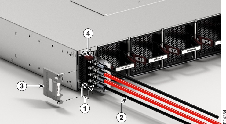
    Figure 57. Connect the DC power cables

    1

    2-hole lug nuts

    3

    Terminal block cover

    2

    DC power cables

    4

    Tab

  4. Close the DC terminal block cover. Tighten the cover screws to a torque value of 5 in-lb.

Step 7

Turn on the circuit breaker at the power source.


Connect High Voltage Power Supply Unit to Power Source

The high voltage PSU (PSU2KW-HVPI or PSU3KW-HVPI) accepts AC, HVAC, or HVDC input power. The HVPI power supply has Anderson power connector for Saf-D-Grid T-latch power cord that can be used for AC, HVAC, or HVDC power.

Procedure


Step 1

Choose your power source (AC, HVAC, or HVDC) and use the Saf-D-Grid T-latch power cord to connect to the PSU.

For power cord details, see Table 2.

Note


To remove the Saf-D-Grid power cord from the power supply, press the latch before pulling the power cord out.

Figure 58. Latch on the Saf-D-Grid power cord

1

Latch

Step 2

Verify that the Saf-D-Grid plug is plugged in completely to secure the built-in retaining latch.

Figure 59. High Voltage (AC, HVAC, or HVDC) Power Connection

1

Anderson power connector

2

Saf-D-Grid T-latch power cord

Step 3

Turn on the circuit breaker for the AC, HVAC, or HVDC power source circuit.