Layer 2 Bridging Services

This module provides the conceptual and configuration information for Layer 2 Bridging Services.

Layer 2 Bridging

You can use Layer 2 bridging services in data centers, campuses, and global networks.

A logical bridge contains the following components:

Bridge Domain

The bridge domain refers to a Layer 2 broadcast domain consisting of a set of physical or virtual ports. Data frames are switched within a bridge domain based on the destination MAC address. Multicast, broadcast, and unknown destination unicast frames are flooded within the bridge domain. In addition, the source MAC address learning is performed on all incoming frames on a bridge domain.

A learned MAC address has an age attribute. MAC address is remembered for a specified aging time and is forgotten if it has not been seen in received traffic for a age period.

A switch assigns a local significant ID to each bridge domain, which is known as the bridge domain ID. Many legacy switches use VLAN as bridge domain ID, which is known as bridging VLAN.

Bridge Port

A logical bridge port identifies a unique network segment in a bridge domain. L2 traffic transits a bridge domain through logical bridge ports. A logical bridge port is independent of the encapsulation of L2 traffic such as VLAN or MPLS. A bridge port performs native bridging functions, such as forwarding, destination MAC address lookup, source MAC address learning, and aging.

MAC Address Table

Forwarding or filtering information table is also known as MAC address table. Each bridge domain has a unique MAC address table. The table consists of MAC address entries. When an Ethernet frame is received on a bridge port, the source MAC address and bridge port are recorded in the MAC address table. This information is used for traffic forwarding in reverse direction.

The following is an example of a MAC address table:

MAC Address Table

MAC Address Ports

1001.1001.2002

Port 2

1001.1001.2003

Port 5

1001.1001.2004

Drop

Note


Drop is not supported in this release.

Replication Member List

A replication member list is a list of virtual bridge ports that allow traffic flooding. A bridge domain has one replication list per each bridge domain.

Configure a Bridge Domain

Perform the following tasks to configure a bridge domain:

Create a Bridge Domain

Perform this task to create a bridge domain.

Configuration Example

Router# configure
Router (config)# l2vpn
Router (config-l2vpn)# bridge group bg1
Router (config-l2vpn-bg)# bridge-domain bd1
Router (config-l2vpn-bg-bd)# commit
Running Configuration

This section shows the bridge domain running configuration.


configure
 l2vpn
  bridge group bg1
   bridge-domain bd1
   !
  !

Associate Members with a Bridge Domain

After a bridge domain is created, perform this task to assign interfaces to the bridge domain.


Router# configure
Router(config)# l2vpn
Router(config-l2vpn)# bridge group bg1
Router(config-l2vpn-bg)# bridge-domain bd1
Router(config-l2vpn-bg-bd)# interface HundredGigE0/0/0/0
Router(config-l2vpn-bg-bd-ac)# commit
Running Configuration

This section shows the running configuration.


configure
 l2vpn
  bridge group bg1
   bridge-domain bd1
    interface HundredGigE0/0/0/0
   !
  !

Configure Bridge Domain Parameter

To configure bridge domain parameter, associate this parameter with a bridge domain:

  • Flooding—Flooding is enabled by default.

Configuration Example

Router# configure
Router (config)# l2vpn
Router (config-l2vpn)# bridge group bg1
Router (config-l2vpn-bg)# bridge-domain bd1
Router (config-l2vpn-bg-bd)# flooding disable
Router (config-l2vpn-bg-bd)# commit
Running Configuration

This section shows the bridge domain parameters running configuration.


configure
 l2vpn
  bridge group bg1
   bridge-domain bd1
    flooding disable
    !
  !

Disable a Bridge Domain

Perform this task to disable a bridge domain. When a bridge domain is disabled, all ACs that are associated with the bridge domain are disabled. You are still able to attach or detach members to the bridge domain and the ACs that are associated with the bridge domain.

Configuration Example

Router# configure
Router (config)# l2vpn
Router (config-l2vpn)# bridge group bg1
Router (config-l2vpn-bg)# bridge-domain bd1
Router (config-l2vpn-bg-bd)# shutdown
Router (config-l2vpn-bg-bd)# commit
Running Configuration

This section shows the running configuration.


configure
 l2vpn
  bridge group bg1
   bridge-domain bd1
    shutdown
   !
  !

VLAN Bridging

VLAN bridging is the simplest mode of L2 bridging. In this mode, all traffic that is received on the switch is either Ethernet II frames or IEEE 802.3 frames.

In modern networks, a majority of the Ethernet frames are in Ethernet II frame format. Legacy L2 protocol traffic, such as spanning tree protocol and CDP are in IEEE 802.3 frame format.

Topology

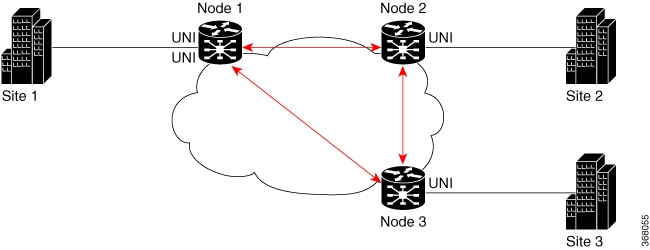
This topology shows a VLAN bridging in a campus network. Each L2 flood domain extends over different floors in the same building, and also other buildings. MAC hosts move freely between office buildings without dropping TCP and IP sessions. The advantage of host mobility is that VLAN bridging is used instead of IP segmentation (subnet routing).

Figure 1. VLAN Bridging

The router at the edge of a core in the network aggregates L2 traffic from local buildings, which are also known as customer edge (CE) devices. The ingress traffic from CE on the router is tagged with either single or double VLAN. The router classifies ingress traffic to different L2 bridge domains and performs optional VLAN tag rewrite. At the egress, the router sends the traffic to a different CE or to a remote router. On the remote router, the traffic is bridged to local office buildings after optional VLAN tag rewrite.

Configure VLAN Bridging

Perform this task to configure VLAN bridging.


/* Configure Attachment Circuits (ACs) */
Router# configure
Router(config)# interface HundredGigE0/0/0/4.1 l2transport
Router(config-subif)# encapsulation dot1q 1
Router((config-subif))# rewrite ingress tag pop 1 symmetric
Router(config-subif))# exit
Router(config)# interface HundredGigE0/0/0/4.2 l2transport
Router(config-subif)# encapsulation dot1q 2
Router((config-subif))# rewrite ingress tag pop 1 symmetric
Router(config-subif))# exit
Router(config)# interface HundredGigE0/0/0/5.1 l2transport
Router(config-subif)# encapsulation dot1q 3
Router((config-subif))# rewrite ingress tag pop 1 symmetric
Router(config-subif))# exit
Router(config)# interface HundredGigE0/0/0/5.2 l2transport
Router(config-subif)# encapsulation dot1q 4
Router((config-subif))# rewrite ingress tag pop 1 symmetric
Router(config-subif))# exit

/* Configure a bridge bomain and associate ACs to a bridge domain */
Router(config)# l2vpn
Router(config-l2vpn)# bridge group bg1
Router(config-l2vpn-bg)# bridge-domain bd1
Router(config-l2vpn-bg-bd)# interface HundredGigE0/0/0/4.1
Router(config-l2vpn-bg-bd-ac)# exit
Router(config-l2vpn-bg-bd)# interface HundredGigE0/0/0/5.1
Router(config-l2vpn-bg-bd-ac)# exit
Router(config-l2vpn-bg-bd)# exit
Router(config-l2vpn-bg)# exit

Router(config-l2vpn)# bridge group bg2
Router(config-l2vpn-bg)# bridge-domain bd2
Router(config-l2vpn-bg-bd)# interface HundredGigE0/0/0/4.2
Router(config-l2vpn-bg-bd-ac)# exit
Router(config-l2vpn-bg-bd)# interface HundredGigE0/0/0/5.2
Router(config-l2vpn-bg-bd-ac)# commit
Running Configuration

This section shows the VLAN bridging running configuration.


interface HundredGigE0/0/0/4.1 l2transport
encapsulation dot1q 1
rewrite ingress tag pop 1 symmetric
!
iinterface HundredGigE0/0/0/4.2 l2transport
encapsulation dot1q 12
rewrite ingress tag pop 1 symmetric
!
interface HundredGigE0/0/0/5.1 l2transport
encapsulation dot1q 3
rewrite ingress tag pop 1 symmetric
!
interface HundredGigE0/0/0/5.2 l2transport
encapsulation dot1q 4
rewrite ingress tag pop 1 symmetric
!
bridge group bg1
  bridge-domain bd1
   interface HundredGigE0/0/0/4.1
   !
   interface HundredGigE0/0/0/5.1
   !
  !
 !
 bridge group bg2
  bridge-domain bd2
   interface HundredGigE0/0/0/4.2
   !
   interface HundredGigE0/0/0/5.2
   !
  !
 !

Verification

Verify VLAN bridging configuration.


Router#show interfaces hundredGigE 0/0/0/4.2
Tue Sep 22 11:32:06.993 PDT
HundredGigE0/0/0/4.2 is up, line protocol is up 
  Interface state transitions: 101
  Hardware is VLAN sub-interface(s), address is c4b2.39da.1620
  Layer 2 Transport Mode
  MTU 1518 bytes, BW 100000000 Kbit (Max: 100000000 Kbit)
     reliability Unknown, txload Unknown, rxload Unknown
  Encapsulation 802.1Q Virtual LAN,
    Outer Match: Dot1Q VLAN 2
    Ethertype Any, MAC Match src any, dest any
  loopback not set,
  Last link flapped 2d10h
  Last input 00:00:00, output 00:00:00
  Last clearing of "show interface" counters 3d18h
     21364536641 packets input, 2734660346522 bytes
     0 input drops, 0 queue drops, 0 input errors
     8420820982 packets output, 1077864630044 bytes
     0 output drops, 0 queue drops, 0 output errors

Router#show l2vpn bridge-domain summary 
Tue Sep 22 11:31:29.819 PDT
Number of groups: 2, VLAN switches: 0
Number of bridge-domains: 510, Up: 510, Shutdown: 0, Partially-
programmed: 0
Default: 510, pbb-edge: 0, pbb-core: 0
Number of ACs: 1530 Up: 1275, Down: 255, Partially-programmed: 0
Number of PWs: 0 Up: 0, Down: 0, Standby: 0, Partially-programmed: 0
Number of P2MP PWs: 0, Up: 0, Down: 0, other-state: 0
Number of VNIs: 0, Up: 0, Down: 0, Unresolved: 0


Router#show l2vpn forwarding bridge-domain location 0/RP0/CPU0 
Tue Sep 22 11:36:01.888 PDT
                                 Bridge       MAC
Bridge-Domain Name               ID     Ports HW addr SW addr Flooding Learning State    
-------------------------------- ------ ----- ------- ------- -------- -------- ---------
bg1:bd1                          511    2     405      405     Enabled  Enabled  UP       
bg1:bd2                          510    2     405      405     Enabled  Enabled  UP       
-----------------------------------------------------------------------------------------

Router#show l2vpn forwarding bridge-domain bg1:bd1 location 0/RP0/CPU0 
Tue Sep 22 11:36:37.141 PDT
                                 Bridge       MAC
Bridge-Domain Name               ID     Ports HW addr SW addr Flooding Learning State    
-------------------------------- ------ ----- ------- ------- -------- -------- ---------
bg1:bd1                          511    2     405      405     Enabled  Enabled  UP       
-----------------------------------------------------------------------------------------

MAC Address-related Parameters

The MAC address table contains a list of known MAC addresses and their forwarding information. The MAC address table is managed and stored on the route processor (RP) card.

These topics provide information about the MAC address-related parameters:

MAC Address Flooding

Ethernet services require that frames that are sent to broadcast addresses and to unknown destination addresses be flooded to all ports. To perform flooding within the broadcast domain, all unknown unicast, broadcast, and multicast addresses are flooded to all attachment circuits. Therefore, a provider edge (PE) device replicates packet across the attachment circuits.

MAC Address-based Forwarding

To forward a frame, a PE must associate a destination MAC address with an attachment circuit. This type of association is provided through a static configuration on each PE or through dynamic learning.

MAC Address Source-based Learning

When a frame arrives on a bridge port and the source MAC address is unknown to the receiving PE router, the source MAC address is associated with the attachment circuit. Outbound frames of the MAC address are forwarded to the appropriate attachment circuit.

MAC address source-based learning uses the MAC address information that is learned in the hardware forwarding path. During the learning process, the data plane hardware notifies control plane about the source MAC address and its associated bridge port. Control plane keeps a note of it on RP and programs the MAC address and its bridge port to MAC tables on all forwarding ASIC in the system.


Note


You can set a MAC address on an AC in a bridge domain. This MAC address is statically programmed on the MAC table. This MAC address can neither age nor move to another AC in the bridge domain through dynamic learning. For example, if a static MAC address is configured on AC1 (port 1) and then, if you send a packet with the same MAC address as source MAC address on AC2 (port 2), then you cannot attach this MAC address to AC2 as a dynamic MAC address. Therefore, do not send any packet with the MAC address which is the same static MAC address configured.


MAC Address Aging

A MAC address in the MAC table is considered valid only for the duration of the MAC address aging time. When the time expires, the relevant MAC entries are removed. When the MAC aging time is configured only under a bridge domain, all the attachment circuits in the bridge domain use that configured MAC aging time.

A bridge forwards, floods, or drops packets based on the bridge table. The bridge table maintains both static entries and dynamic entries. Static entries are entered by the network manager or by the bridge itself. Dynamic entries are entered by the bridge learning process. A dynamic entry is automatically removed after a specified length of time, known as aging time, from the time the entry was created or last updated.

If hosts on a bridged network are likely to move, decrease the aging-time to enable the bridge to adapt to the change quickly. If hosts do not transmit continuously, increase the aging time to record the dynamic entries for a longer time, thus reducing the possibility of flooding when the hosts transmit again.

The range of MAC address aging time is from 300 seconds to 30,000 seconds. The maximum MAC address aging time among all bridges is considered for calculating the age. You cannot configure the MAC address aging time on each AC interface. Configure MAC address aging time in the bridge domain configuration mode. There is no show command to display the highest MAC address aging time.


Note


When you configure the different aging time for each bridge domains, the system considers the highest value of all the bridge domains. For example, if you configure the aging time on bd1 as 300 seconds, on bd2 as 600 seconds, and bd3 as 800 seconds, MAC address aging time is taken as 800 seconds for all the bridge domains bd1, bd2, and bd3. All the three bridge domains age out at 800 seconds.


MAC Address Limit

The MAC address limit is used to alert the user when MAC addresses in a bridge domain exceed a certain threshold. The maximum MAC address limit is 131072.

When a limit is exceeded, the system displays the following notifications:

  • Syslog (default)

  • Simple Network Management Protocol (SNMP) trap

  • Syslog and SNMP trap

  • None (no notification)

To generate syslogs messages and SNMP trap notifications, use the mac limit notification both command in the L2VPN bridge-domain configuration mode.

MAC address limit action applies only when the number of local MAC addresses exceeds the configured limit. When the MAC limit threshold is not configured, the default MAC address limit is 131072.

Configure MAC-related Parameters

These tasks describe how to configure the MAC address-related parameters:

Configure the MAC Address Source-based Learning

MAC address source-based learning is enabled by default, Perform this task to disable the MAC address source-based learning.

Configuration Example

Router# configure
Router (config)# l2vpn
Router (config-l2vpn)# bridge group bg1
Router (config-l2vpn-bg)# bridge-domain bd1
Router (config-l2vpn-bg-bd)# mac
Router (config-l2vpn-bg-bd-mac)# learning disable
Router (config-l2vpn-bg-bd-mac)# commit
Running Configuration

This section shows the MAC address source-based learning running configuration.


configure
 l2vpn
  bridge group bg1
   bridge-domain bd1
    mac
    learning disable
    !
  !

Configure the MAC Address Limit

Perform this task to configure the parameters for the MAC address limit.


Note


You cannot set the custom value for the MAC address limit. You can configure the MAC address limit only to a maximum value, which is 131072.


Configuration Example

Router# configure
Router (config)# l2vpn
Router (config-l2vpn)# bridge group bg1
Router (config-l2vpn-bg)# bridge-domain bd1
Router (config-l2vpn-bg-bd)# mac
Router (config-l2vpn-bg-bd-mac)# limit
Router (config-l2vpn-bg-bd-mac-limit)# maximum 131072
Router (config-l2vpn-bg-bd-mac-limit)# notification both
Router (config-l2vpn-bg-bd-mac-limit)# exit
Router (config-l2vpn-bg-bd)# exit
Router (config-l2vpn-bg-bd)# mac limit threshold 80
Router (config-l2vpn-bg-bd-mac-limit)# commit
Running Configuration

This section shows the MAC address limit running configuration.


configure
 l2vpn
  bridge group bg1
   bridge-domain bd1
    mac
     limit
     maximum 131072
     notification both
    !
    mac limit threshold 80
   !
  !

Configure the MAC Address Aging

Perform this task to configure the parameters for MAC address aging.

Configuration Example

Router# configure
Router (config)# l2vpn
Router (config-l2vpn)# bridge group bg1
Router (config-l2vpn-bg)# bridge-domain bd1
Router (config-l2vpn-bg-bd)# mac
Router (config-l2vpn-bg-bd-mac)# aging
Router (config-l2vpn-bg-bd-mac-aging)# time 300
Router (config-l2vpn-bg-bd-mac-aging)# commit
Running Configuration

This section shows the MAC address aging running configuration.


configure
 l2vpn
  bridge group bg1
   bridge-domain bd1
    mac
     aging
      time 300
     !
    !

Flooding Disable

The Flooding Disable feature prevents forwarding of Broadcast, Unknown-unicast and Multicast (BUM) traffic on the bridge domain. You can disable flooding of BUM traffic at the bridge level. By disabling flooding at the bridge level, you can prevent forwarding of BUM traffic on AC).

You can also disable only unknown unicast traffic at the bridge level. By disabling flooding of unknown unicast traffic at the bridge level, you can prevent forwarding of unknown unicast traffic on AC.

Configure Flooding Disable

Perform this task to configure Flooding Disable feature.

You can disable flooding of:

  • BUM traffic at the bridge level

  • Unknown-unicast traffic at the bridge level

However, the flooding disable of unknown-unicast traffic at the bridge level takes effect only when the flooding disable command is not configured for BUM traffic at the bridge level.

Configuration Example


/* Configuration to disable flooding of BUM traffic at the bridge level */
Router# configure
Router(config)#l2vpn
Router(config-l2vpn)#bridge group bg1
Router(config-l2vpn-bg)#bridge-domain bd1
Router(config-l2vpn-bg-bd)#flooding disable
Router(config-l2vpn-bg-bd)#commit 

/* Configuration to disable flooding of unknown-unicast traffic at the bridge level */
Router# configure
Router(config)#l2vpn
Router(config-l2vpn)#bridge group bg1
Router(config-l2vpn-bg)#bridge-domain bd1
Router(config-l2vpn-bg-bd)#flooding unknown-unicast disable
Router(config-l2vpn-bg-bd)#commit

Running Configuration

This section shows flooding disable running configuration.


/* Configuration to disable flooding of BUM traffic at the bridge level */
configure
 l2vpn
  bridge group bg1
   bridge-domain bd1
    flooding disable
   !

/* Configuration to disable flooding of unknown-unicast traffic at the bridge level */
configure
 l2vpn
  bridge group bg1
   bridge-domain bd1
    flooding unknown-unicast disable
   !
  !

Virtual Private LAN Bridging Services

Table 1. Feature History Table

Feature Name

Release Information

Feature Description

Virtual Private LAN Bridging Services

Release 7.3.2

This feature employs PE routers connected by a mesh of tunnels, enabling you to connect multiple customer devices in a single bridged domain. Such a setup allows service providers to seamlessly offer a variety of services that they can provision rapidly.

A service provider can offer VPLS service to multiple customers over the MPLS network by defining different bridged domains for different customers. Packets from one bridged domain are never carried over or delivered to another bridged domain, thus ensuring the privacy of the LAN service.

VPLS is a multipoint Layer 2 VPN technology that connects two or more provider edge (PE) devices using bridging. A bridge domain, which is the building block for multipoint bridging, is present on each of the PE routers. The access connections to the bridge domain on a PE router are called attachment circuits. The attachment circuits can be a set of physical ports, virtual ports, or both that are connected to the bridge at each PE device in the network.

Now, the service provider network starts switching the packets within the bridged domain specific to the customer by looking at destination MAC addresses. All traffic with unknown, broadcast, and multicast destination MAC addresses is flooded to all the connected customer edge devices, which connect to the service provider network. The network-facing provider edge devices learn the source MAC addresses as the packets are flooded. The traffic is unicasted to the customer edge device for all the learned MAC addresses.

VPLS Architecture

The VPLS architecture allows for the end-to-end connection between the PE routers to provide multipoint ethernet services. Following figure shows a VPLS architecture illustrating the interconnection between the network provider edge (N-PE) nodes over an IP/MPLS network.

Figure 2. VPLS Architecture

The VPLS network requires the creation of a bridge domain (Layer 2 broadcast domain) on each of the PE routers. The VPLS provider edge device holds all the VPLS forwarding MAC tables and bridge domain information. In addition, it is responsible for all flooding broadcast frames and multicast replications.

The PEs in the VPLS architecture are connected with a full mesh of Pseudowires (PWs). A Virtual Forwarding Instance (VFI) is used to interconnect the mesh of pseudowires. A bridge domain is connected to a VFI to create a Virtual Switching Instance (VSI), that provides Ethernet multipoint bridging over a PW mesh. VPLS network links the VSIs using the MPLS pseudowires to create an emulated Ethernet Switch.

With VPLS, all customer equipment (CE) devices participating in a single VPLS instance appear to be on the same LAN and, therefore, can communicate directly with one another in a multipoint topology, without requiring a full mesh of point-to-point circuits at the CE device.

VPLS transports Ethernet IEEE 802.3, VLAN IEEE 802.1q, and VLAN-in-VLAN (q-in-q) traffic across multiple sites that belong to the same Layer 2 broadcast domain. VPLS offers simple VLAN services that include flooding broadcast, multicast, and unknown unicast frames that are received on a bridge. The VPLS solution requires a full mesh of pseudowires that are established among PE routers. The VPLS implementation is based on Label Distribution Protocol (LDP)-based pseudowire signaling.

Pseudowires

A pseudowire (PW) is a point-to-point connection between pairs of PE routers. Its primary function is to emulate services like Ethernet over an underlying core MPLS network through encapsulation into a common MPLS format. By encapsulating services into a common MPLS format, a pseudowire allows carriers to converge their services to an MPLS network.


Note


Multiple PWs within a bridge domain are supported. However, multiple PWs to the same destination within the same bridge domain are not supported.


Perform this task to configure a pseudowire under a bridge domain.


Router# configure
Router(config)# l2vpn
Router(config-l2vpn)# bridge group BG1
Router(config-l2vpn-bg)# bridge-domain BD1
Router(config-l2vpn-bg-bd)# neighbor 10.0.0.2 pw-id 1
Router(config-l2vpn-bg-bd-pw)# commit

Running Configuration

This section shows the pseudowire running configuration.


l2vpn
 bridge group BG1
  bridge-domain BD1
   neighbor 10.0.0.2 pw-id 1
  !
!

Pseudowire Statistics

  • Use the hw-module profile l2fib pw-stats command to enable PW statistics. After you enable PW statistics, you must reload all slots for configuration to take effect.

  • Pseudowire statistics are not supported on line cards based on Q100 Silicon.

  • Only aggregate and unicast statistics are supported for ingress PW (PW disposition). Multicast, broadcast, and unknown unicast statistics are not supported for PW.

  • Statistics resource is limited, and enabling statistics on PW impacts forwarding performance; therefore, you must enable PW statistics manually using the hw-module profile command.

The following example shows the pseudowire statistics before and after the reload:


Before the reload:
Router# show hw-module profile l2fib
--------------------------------------------------------------
Knob                           Status        Applied    Action
--------------------------------------------------------------
PW-Stats                      Configured      No        Reload /*configured but not reloaded/applied yet*/
BD-Flush-Convergence          Unconfigured    N/A       None

After the reload:
Router# show hw-module profile l2fib
--------------------------------------------------------------
Knob                           Status        Applied    Action
--------------------------------------------------------------
PW-Stats                      Configured      Yes       None /*configured but not reloaded/applied yet*/
BD-Flush-Convergence          Unconfigured    N/A       None

The following output shows the aggregate and unicast statistics for ingress PW:


Router# show l2vpn forwarding bridge-domain detail location 0/RP0/CPU0 | inc "state:Nbor|XC ID|received"
    XC ID: 0x1
      packets: received 2081 (multicast 0, broadcast 2081, unknown unicast 0, unicast 0), sent 998
      bytes: received 266368 (multicast 0, broadcast 266368, unknown unicast 0, unicast 0), sent 127744
    XC ID: 0x2
      packets: received 0 (multicast 0, broadcast 0, unknown unicast 0, unicast 0), sent 3079
      bytes: received 0 (multicast 0, broadcast 0, unknown unicast 0, unicast 0), sent 394112
    XC ID: 0xa0000001
      packets: received 998 (unicast 0), sent 1996
      bytes: received 145708 (unicast 0), sent 307384

Virtual Forwarding Instance

VPLS is based on the characteristic of virtual forwarding instance (VFI). A VFI is a virtual bridge port that is capable of performing native bridging functions, such as forwarding, based on the destination MAC address, source MAC address learning and aging, and so forth.

A VFI is created on the PE router for each VPLS instance. The PE routers make packet-forwarding decisions by looking up the VFI of a particular VPLS instance. The VFI acts like a virtual bridge for a given VPLS instance. More than one attachment circuit belonging to a given VPLS are connected to the VFI. The PE router establishes emulated VCs to all the other PE routers in that VPLS instance and attaches these emulated VCs to the VFI. Packet forwarding decisions are based on the data structures maintained in the VFI.

Configure a VFI

Perform this task to confiure a Virtual Forwarding Instance (VFI) on all provider edge devices under the bridge domain and associate a pseudowire with the VFI.


Router# configure
Router(config)# l2vpn
Router(config-l2vpn)# bridge group BG1
Router(config-l2vpn-bg)# bridge-domain BD1
Router(config-l2vpn-bg-bd)# vfi V1
Router(config-l2vpn-bg-bd-vfi)# neighbor 10.0.0.2 pw-id 1
Router(config-l2vpn-bg-bd-vfi-pw)# commit

Running Configuration

This section shows the VFI running configuration.


l2vpn
 bridge group BG1
  bridge-domain BD1
   vfi V1
    neighbor 10.0.0.2 pw-id 1
  !
!

VPLS PW Transport Types

The following are the supported transport types for VPLS PW:

  • LDP

  • Segment Routing

  • LDP over TE

  • BGP-LU for inter-AS C topology

Pseudowire Types and Transported Tags

The following pseudowire types are supported:

  • Ethernet Port Mode—Ethernet port mode is supported for pseudowire over MPLS. The virtual connection (VC) type 5 is known as an Ethernet port-based PW. In this mode, both ends of a pseudowire are connected to Ethernet ports and allow a complete ethernet trunk to be transported. The ingress PE transports frames received on a main interface or subinterface. This feature nullifies the need for a dummy tag and reduces overhead. In addition, frame tagging is no longer necessary.

  • VLAN Mode—VLAN mode is supported for pseudowire over MPLS. A virtual connection (VC) type 4 is the VLAN-based PW. The ingress PE does not remove the incoming VLAN tags that are to be transported over the PW. VC type 4 inserts an extra dummy tag with VLAN 0 onto the frame which is removed on the other side. This mode helps the service provider to segregate traffic for each customer based on the VLAN.

    In this mode, each VLAN on a customer-end to provider-end link can be configured as a separate L2VPN connection using virtual connection (VC) type 4. VLAN-based (VC Type 4) pseudowires ensure a VLAN tag is transported over the pseudowire by pushing a dummy tag at the attachment circuit ingress. If the rewrite rule pushes two or more tags, a dummy tag is not needed because these VLAN tags are transported over the pseudowire. On the remote router, the dummy tag, if added, is removed before egress.


Note


A mix of type 4 and type 5 PWs under the same VFI is not supported. All PWs must be of the same type.


Pseudowire Control-Word

A control-word is an optional 4-byte field located between the MPLS label stack and the Layer 2 payload in the pseudowire packet. The control word carries generic and Layer 2 payload-specific information.

The control-word has the following functions:

  • Pad small packets—If the AToM packet does not meet the minimum length then the frame is padded to meet the minimum length on the ethernet link. Because the MPLS header has no length that indicates the length of the frames, the control word holds a length field indicating the length of the frame. If the received AToM packet in the egress PE router has a control word with a length that is not 0, the router knows that padding was added and can correctly remove the padding before forwarding the frames.

  • Carry control bits of the Layer 2 header of the transported protocol.

  • Preserve the sequence of the transported frames—Preserve the sequence of the transported frames—The first packet sent onto the PW has a sequence number of 1 and increments for each subsequent packet by one until it reaches 65535. If such out of sequence packets are detected, the packets are dropped. The re-ordering for the out-of-sequence packet is not performed.

  • Load balancing—Load balancing allows the router to correctly identify the Ethernet PW packet over an IP packet, thus preventing the selection of wrong equal-cost multipath (ECMP) path for the packet that leads to the misordering of packets. The control-word keyword is inserted immediately after the MPLS label to separate the payload from the MPLS label over a PW. The control word carries layer 2 control bits and enables sequencing.

  • Facilitate fragmentation and reassembly—This is used to indicate the payload fragmentation:

    • 00 = unfragmented

    • 01 = 1st fragment

    • 10 = last fragment

    • 11 = intermediate fragment

Configure Pseudowire Control-Word

Perform this task to configure the pseudowire control-word.


Router# configure
Router(config)# l2vpn
Router(config-l2vpn)# pw-class path1
Router(config-l2vpn-pwc)# encapsulation mpls
Router(config-l2vpn-pwc-mpls)# control-word
Router(config-l2vpn-pwc-mpls)# exit
Router(config-l2vpn-pwc)# exit
Router(config-l2vpn)# bridge group BG1
Router(config-l2vpn-bg)# bridge-domain BD1
Router(config-l2vpn-bg-bd)# neighbor 10.0.0.2 pw-id 1
Router(config-l2vpn-bg-bd-pw)# pw-class path1
Router(config-l2vpn-bg-bd-pw)# commit

Running Configuration

This section shows the pseudowire control-word running configuration.


l2vpn
 pw-class path1
  encapsulation mpls
   control-word
 bridge group BG1
  bridge-domain BD1
   neighbor 10.0.0.2 pw-id 1
    pw-class path1
  !
!

Load Balancing using Flow Aware Transport Pseudowire (FAT PW)

Routers typically load balance traffic based on the lowermost label in the label stack which is the same label for all flows on a given pseudowire. This can lead to asymmetric load balancing. The flow, in this context, refers to a sequence of packets that have the same source and destination pair. The packets are transported from a source provider edge (PE) to a destination PE.

Flow Aware Transport Pseudowires (FAT PW) provides the capability to identify individual flows within a pseudowire and provide routers the ability to use these flows to load balance traffic. FAT PWs are used to load balance traffic in the core when equal-cost multipaths (ECMP) are used. A flow label is created based on individual packet flows entering a pseudowire; and is inserted as the lowermost label in the packet. Routers can use the flow label for load balancing which provides a better traffic distribution across ECMP paths or link-bundled paths in the core.

The following figure shows a FAT PW with two flows distributing over ECMPs and bundle-links.

Figure 3. FAT PW with two flows distributing over ECMPs and Bundle-Links

An additional label is added to the stack, called the flow label, which contains the flow information of a virtual circuit (VC). A flow label is a unique identifier that distinguishes a flow within the PW, and is derived from source and destination MAC addresses, and source and destination IP addresses. The flow label contains the end of the label stack (EOS) bit set and inserted after the VC label and before the control word (if any). The ingress PE calculates and forwards the flow label. The FAT PW configuration enables the flow label. The egress PE discards the flow label such that no decisions are made.

Core routers perform load balancing using the flow-label in the FAT PW with other information like MAC address and IP address. The flow-label adds greater entropy to improve traffic load balancing. Therefore, it’s possible to distribute flows over ECMPs and link bundles.

You cannot send MPLS OAM ping traffic over a FAT PW, since there is no flow label support for MPLS OAM.

Configure load balancing using FAT PW

Perform this task to enable load balancing with ECMP and FAT PW. Creating a PW class in L2VPN configuration leads to load balancing.


Router# configure
Router(config)# l2vpn
Router(config-l2vpn)# pw-class FLOW
Router(config-l2vpn-pwc)# encapsulation mpls
Router(config-l2vpn-pwc-mpls)# flow-label both
Router(config-l2vpn-pwc-mpls)# exit
Router(config-l2vpn-pwc)# exit
Router(config-l2vpn)# bridge group BG1
Router(config-l2vpn-bg)# bridge-domain BD1
Router(config-l2vpn-bg-bd)# neighbor 10.0.0.2 pw-id 1
Router(config-l2vpn-bg-bd-pw)# pw-class FLOW
Router(config-l2vpn-bg-bd-pw)# commit

Running Configuration

This section shows the running configuration.


l2vpn
 pw-class FLOW
  encapsulation mpls
   flow-label both
 bridge group BG1
  bridge-domain BD1
   neighbor 10.0.0.2 pw-id 1
    pw-class FLOW
  !
!

VPLS Discovery and Signaling

VPLS is a Layer 2 multipoint service and it emulates LAN service across a WAN service. VPLS enables service providers to interconnect several LAN segments over a packet-switched network and make it behave as one single LAN. Service provider can provide a native Ethernet access connection to customers using VPLS.

The VPLS control plane consists of two important components, autodiscovery and signaling:

  • VPLS Autodiscovery eliminates the need to manually provision VPLS neighbors. VPLS Autodiscovery enables each VPLS PE router to discover the other provider edge (PE) routers that are part of the same VPLS domain.

  • Once the PEs are discovered, pseudowires (PWs) are signaled and established across each pair of PE routers forming a full mesh of PWs across PE routers in a VPLS domain.

Figure 4. VPLS Autodiscovery and Signaling

BGP-based VPLS Autodiscovery

An important aspect of VPN technologies, including VPLS, is the ability of network devices to automatically signal to other devices about an association with a particular VPN. Autodiscovery requires this information to be distributed to all members of a VPN. VPLS is a multipoint mechanism for which BGP is well suited.

BGP-based VPLS autodiscovery eliminates the need to manually provision VPLS neighbors. VPLS autodiscovery enables each VPLS PE router to discover the other provider edge (PE) routers that are part of the same VPLS domain. VPLS Autodiscovery also tracks when PE routers are added to or removed from the VPLS domain. When the discovery process is complete, each PE router has the information required to setup VPLS pseudowires (PWs).

Even when BGP autodiscovery is enabled, pseudowires can be manually configured for VPLS PE routers that are not participating in the autodiscovery process.

BGP Auto Discovery With BGP Signaling

The implementation of VPLS in a network requires the establishment of a full mesh of PWs between the provider edge (PE) routers. The PWs can be signaled using BGP signaling.

Figure 5. Discovery and Signaling Attributes

Discovery and Signaling Attributes

The BGP signaling and autodiscovery scheme has the following components:

  • A means for a PE to learn which remote PEs are members of a given VPLS. This process is known as autodiscovery.

  • A means for a PE to learn the pseudowire label expected by a given remote PE for a given VPLS. This process is known as signaling.

The BGP Network Layer Reachability Information (NLRI) takes care of the above two components simultaneously. The NLRI generated by a given PE contains the necessary information required by any other PE. These components enable the automatic setting up of a full mesh of pseudowires for each VPLS without having to manually configure those pseudowires on each PE.

NLRI Format for VPLS with BGP AD and Signaling

The following figure shows the NLRI format for VPLS with BGP AD and Signaling
Figure 6. NLRI Format

NLRI Format

BGP Auto Discovery With LDP Signaling

Signaling of pseudowires requires exchange of information between two endpoints. Label Distribution Protocol (LDP) is better suited for point-to-point signaling. The signaling of pseudowires between provider edge devices, uses targeted LDP sessions to exchange label values and attributes and to configure the pseudowires.

Figure 7. Discovery and Signaling Attributes

A PE router advertises an identifier through BGP for each VPLS. This identifier is unique within the VPLS instance and acts like a VPLS ID. The identifier enables the PE router receiving the BGP advertisement to identify the VPLS associated with the advertisement and import it to the correct VPLS instance. In this manner, for each VPLS, a PE router learns the other PE routers that are members of the VPLS.

The LDP protocol is used to configure a pseudowire to all the other PE routers. FEC 129 is used for the signaling. The information carried by FEC 129 includes the VPLS ID, the Target Attachment Individual Identifier (TAII) and the Source Attachment Individual Identifier (SAII).

The LDP advertisement also contains the inner label or VPLS label that is expected for the incoming traffic over the pseudowire. This enables the LDP peer to identify the VPLS instance with which the pseudowire is to be associated and the label value that it is expected to use when sending traffic on that pseudowire.

NLRI and Extended Communities

The following figure depicts Network Layer Reachability Information (NLRI) and extended communities (Ext Comms).

Figure 8. NLRI and Extended Communities

CFM on VPLS

Table 2. Feature History Table

Feature Name

Release Information

Feature Description

CFM on VPLS

Release 7.3.2

This feature helps you monitor and manage a Layer 2 VPN running VPLS. It does so by providing proactive network management, enabling fault detection and isolation, and reporting end-to-end ethernet connectivity issues.

This feature enables you to monitor the VPLS network using connectivity fault management (CFM). CFM is a service-level Operations and Maintenance (OAM) protocol that provides a mechanism for monitoring and troubleshooting end-to-end Ethernet services. This feature provides high speed Layer 2 and Layer 3 services with high resiliency and less operational complexity to different market segments.

CFM on VPLS services support CFM continuity check and ITU-T Y.1731 functions.

The following are the key components of CFM:

  • Maintenance Domain (MD)—A maintenance domain is a management space for managing and administering a network. A domain is owned and operated by a single entity and defined by the set of ports internal to the domain and at its boundary. Maintenance Domain divides the network into different operational and administrative domains. For example, customers, service providers, and operators may belong to different domains. For securely maintaining and monitoring an administrative domain, the administrative domain is linked to one maintenance domain. MD supports different domain levels from 0 to 7. A unique maintenance level in the range of 0 to 7 is assigned to each domain by a network administrator. Levels and domain names are useful for defining the hierarchical relationship that exists among domains. The hierarchical relationship of domains parallels the structure of customer, service provider, and operator. The larger the domain, the higher the level value. For example, a customer domain would be larger than an operator domain. The customer domain may have a maintenance level of 7 and the operator domain may have a maintenance level of 0. Typically, operators would have the smallest domains and customers the largest domains, with service provider domains between them in size. All levels of the hierarchy must operate together.

  • Maintenance Association/Service (MA)—A maintenance association identifies a service that can be uniquely identified within the maintenance domain. Maintenance association monitors the connectivity of a particular service instance in an MD. MA is defined by a set of Maintenance End Points (MEP) at the edge of a domain.

  • Maintenance Point—A maintenance point is a demarcation point on an interface (port) that participates in CFM within a maintenance domain. Maintenance points on device ports act as filters that confine CFM frames within the bounds of a domain by dropping frames that do not belong to the correct level. Maintenance points must be explicitly configured on Cisco devices. Two classes of maintenance points exist, Maintenance End Point (MEP) and Maintenance Intermediate Point (MIP). MIP is not supported.

  • Maintenance End Point (MEP)—Is a demarcation point on an interface that participates in CFM within a maintenance domain. MEPs drop all lower-level frames and forward all higher-level frames. MEPs are defined per maintenance domain (level) and service (S-VLAN or ethernet virtual circuit (EVC)). They are at the edge of a domain and define the boundary and confine CFM messages within that boundary. MEPs can proactively transmit CFM continuity check messages (CCMs) and at the request of an administrator, transmit traceroute, and loopback messages.

    The following MEPs are used:

    • Down MEPs are outward-facing MEPs that communicate through the wire. Down MEPs use the port MAC address and not the bridge-domain MAC address. Down MEPs are used for services spanning a single L2 link.

    • Up MEPs are inward-facing MEPs that communicate through the bridge relay function. Up MEP sends and receives CFM frames at its level through the relay function. Up MEPs are commonly used for services across multiple switches for end-to-end connection with xconnect L2 AC interfaces.

The following protocols are used for CFM:

  • Continuity Check Protocol—This protocol is used for fault detection and notification and carries the status of port on which MEP is configured. It is unidirectional and requires no response. This protocol is transmitted at a configurable periodic interval by MEP.

  • Loopback Protocol—This protocol is used for fault verification. MEP can transmit a unicast loopback message (LBM) to a MEP in the same MA. The receiving MP responds by transforming the LBM into a unicast loopback back reply (LBR) sent back to the originating MEP.

  • Linktrace Protocol—This protocol is used for path discovery and fault isolation. MEP can transmit a multicast message (LTM) in order to discover the MPs and path to a MEP in the same MA.

For more information about CFM, see the Configuring Ethernet OAM chapter in the Interface and Hardware Component Configuration Guide for Cisco 8000 Series Routers.

Restrictions

  • Up MEPs and down MEPs are not supported on the same interface. But, multiple MEPs of the same direction are supported. For example, all up MEPs or all down MEPs on the same interface are supported.

  • Maintenance Intermediate Point (MIP) is not supported on any interface.

  • MEPs on bundle member interface are limited to maintenance domain level 0.

  • Software offload is supported only on bundle member down MEPs.

Supported Offload Types and CCM Timer Values for CFM on VPLS

Table 3. Feature History Table

Feature Name

Release Information

Feature Description

CFM Hardware Offload

Release 7.9.1

CFM Hardware offloading allows to implement connectivity and fault monitoring for physical and bundle interfaces, using continuity check messages (CCM). This feature helps to detect network failure with short CCM intervals, which enables the router to recover from the failure without dropping the packets.

Depending on where the continuity check messages (CCMs) are processed, offload is categorized into the following types:

  • Software offload—When CCMs are processed by the line card CPU, offload type is known as software offload. Software offload is supported only on bundle interface.

  • Hardware offload—When CCMs are processed by network processor (NP), offload type is known as hardware offload.

  • Non-offload—When CCMs are processed by route processor (RP), offload type is known as non-offload.

CCM intervals are the intervals in which CCMs are sent and received. If the CCMs are not received within the configured interval, the CFM MEP goes down. The following table shows the supported CCM timers for the offload types:

Interface Type

Offload Type

Supported CCM Timers

Physical Interfaces and Subinterfaces

Non-offload

  • 1 sec

  • 10 sec

  • 1 min

  • 10 min

Hardware offload

  • 3.3 ms

  • 10 ms

Bundle Members

Non-offload

  • 1 sec

  • 10 sec

  • 1 min

  • 10 min

Software offload

  • 100 ms

Bundle Interfaces and Subinterfaces

Non-offload

  • 1 sec

  • 10 sec

  • 1 min

  • 10 min

Hardware offload

  • 3.3 ms

  • 10 ms

Configure CFM on VPLS

Figure 9. CFM on VPLS: Full Mesh Topology
This image shows the full mesh topology of CFM on EVPN ELAN.

In this topology, node 1, 2 and 3 are PE routers. All nodes are in a VPLS mesh and CFM is configured to monitor the connectivity between them.

Perform the following tasks on PE routers to configure CFM on VPLS:

  • Enable CFM service continuity check

  • Configure MEP cross-check

  • Enable CFM for the interface

Configuration Example

Perform these tasks on the PE routers:

Enable CFM continuity check


Router# configure
Router# ethernet cfm
Router(config-cfm# domain vpls_bgp level 3 id null
Router(config-cfm-dmn)# service vpls_bgp_1 bridge group vpls bridge-domain vpls-1 id number 1000
Router(config-cfm-dmn-svc)# continuity-check interval 10s

Repeat the above configurations for node 2 and node 3.

Configure MEP cross-check


Router(config-cfm-dmn-svc)# mep crosscheck
Router(config-cfm-dmn-svc-xcheck)# mep crosscheck
Router(config-cfm-dmn-svc-xcheck)# exit
Router(config-cfm-dmn-svc)# log continuity-check errors
Router(config-cfm-dmn-svc)# log continuity-check mep changes
Router(config-cfm-dmn-svc)# commit

Repeat the above configurations for node 2 and node 3, with the respective mep-id values.

Enable CFM on the interface


Router# configure
Router(config)# interface HundredGigE0/0/0/2/0.1000 l2transport
Router(config-subif)# encapsulation dot1q 1000
Router(config-subif)# ethernet cfm
Router(config-if-cfm)# mep domain vpls_bgp service vpls_bgp_1 mep-id 1
Router(config-if-cfm-mep)# commit

You must repeat the above configurations for node 2 and node 3, with the respective mep-id values.

Running Configuration

This sections shows the running configuration on node 1.


ethernet cfm
 domain vpls_bgp level 3 id null
  service vpls_bgp_1 bridge group vpls bridge-domain vpls-1 id number 1000
   continuity-check interval 10s
   mep crosscheck
    mep-id 8191
   !
   log continuity-check errors
   log continuity-check mep changes
  !
!
!
interface HundredGigE0/0/0/2/0.1000 l2transport
 encapsulation dot1q 1000
 ethernet cfm
  mep domain vpls_bgp service vpls_bgp_1 mep-id 1
 !

Verification

Verify that you have configured CFM on VPLS successfully. The following output shows the domain ID number along with the maintenance domain level and shows the interface on which the Up MEP is configured.

Router(PE1)# show ethernet cfm peer meps 
Flags:
> - Ok                          I - Wrong interval
R - Remote Defect received      V - Wrong level
L - Loop (our MAC received)     T - Timed out
C - Config (our ID received)    M - Missing (cross-check)
X - Cross-connect (wrong MAID)  U - Unexpected (cross-check)
* - Multiple errors received    S - Standby

Domain id_no (level 3), Service id_no_vpws_1
Up MEP on TenGigE0/0/0/2/0.1 MEP-ID 1
================================================================================
St    ID MAC Address    Port    Up/Downtime   CcmRcvd SeqErr   RDI Error
-- ----- -------------- ------- ----------- --------- ------ ----- -----
 >  8191 b0c5.3cff.c0c1 Up      00:01:26            9      0     4     0

Router(PE1)# show ethernet cfm peer meps detail 
Domain id_no (level 3), Service id_no_vpws_1
Up MEP on TenGigE0/0/0/2/0.1 MEP-ID 1
================================================================================
Peer MEP-ID 8191, MAC b0c5.3cff.c0c1
   CFM state: Ok, for 00:01:44
   Port state: Up
   CCMs received: 11
     Out-of-sequence:             0
     Remote Defect received:      4
     Wrong level:                 0
     Cross-connect (wrong MAID):  0
     Wrong interval:              0
     Loop (our MAC received):     0
     Config (our ID received):    0
   Last CCM received 00:00:04 ago:
     Level: 3, Version: 0, Interval: 10s
     Sequence number: 8495, MEP-ID: 8191
     MAID: NULL, UINT: 1
     Chassis ID: Local: Eyrie; Management address: 'Not specified'
     Port status: Up, Interface status: Up

Router(PE1)# show ethernet cfm local meps verbose 
Domain id_no (level 3), Service id_no_vpws_1
Up MEP on TenGigE0/0/0/2/0.1 MEP-ID 1
================================================================================
  Interface state: Up      MAC address: d46a.355c.b808
  Peer MEPs: 1 up, 0 with errors, 0 timed out (archived)
  Cross-check errors: 0 missing, 0 unexpected

  CCM generation enabled:  Yes, 10s (Remote Defect detected: No)
  AIS generation enabled:  No
  Sending AIS:             No
  Receiving AIS:           No
  Sending CSF:             No
  Receiving CSF:           No

  Packet        Sent      Received
  ------  ----------  ---------------------------------------------------------
  CCM           8508            24  (out of seq: 0)

Split-Horizon Groups

Table 4. Feature History Table

Feature Name

Release Information

Feature Description

Split-Horizon Groups

Release 7.3.2

This feature prevents packets from going into endless loops by aggregating attachment circuits and pseudowires into one of three groups called split-horizon groups. Split-horizon groups operate on the principle that members within a group will not send traffic to each other thereby preventing traffic loops.

Split horizon is a method for preventing loops in a network by placing forwarding or flooding restrictions between bridge ports based on group membership. The bridge domain aggregates attachment circuits (ACs) and pseudowires (PWs) in one of three groups called split-horizon groups. When applied to bridge domains, split-horizon refers to the flooding and forwarding behavior between members of a split-horizon group. Bridge domain traffic is either unicast or flooding.

Traffic flooding is performed for broadcast, multicast and unknown unicast destination address. Unicast traffic consists of frames sent to bridge-ports where the destination MAC address is known.

Flooding traffic consists of:

  • Unknown unicast destination MAC address frames

  • frames sent to Ethernet multicast addresses (Spanning Tree BPDUs, and so on)

  • Ethernet broadcast frames (MAC address FF-FF-FF-FF-FF-FF)

Members within certain groups are forbidden to send traffic to each other. Members in different groups can send traffic to each other without restriction.

The following table describes how frames received on one member of a split-horizon group are treated and if the traffic is forwarded to the other members of the same split-horizon group. It describes the behavior of forwarding and flooding within and between groups as well as the assignment of Bridge Ports (BPs) to groups:

Table 5. Supported Split-Horizon Groups

Split-Horizon Group

Behavior

0

Default AC group. There is no forwarding and flooding restrictions. Forwards and floods traffic within the group and between all groups.

By default, all L2 ACs are added to this group by default. You cannot assign L2 ACs manually through the CLI.

1

Default VFI (core) PW group. Forwarding or flooding of traffic is restricted between bridge ports in this group. Forwarding or flooding of traffic to all other groups is allowed. All VFI PWs are added to this group. You cannot assign VFI PWs manually through the CLI.

2

Optional AC group. Forwarding or flooding of traffic is restricted between bridge ports in this group. Forwarding or flooding traffic to all other groups is allowed. You can manually add ACs, and not VFI PWs using the CLI.

Configuration Example

Perform this task to configure the split-horizon groups feature:


Router# configure
Router(config)# l2vpn
Router(config-l2vpn)# bridge group bg
Router(config-l2vpn-bg)# bridge-domain bd
Router(config-l2vpn-bg-bd-ac)# interface Ten0/7/0/22/0 <- (split-horizon group 0, default)
Router(config-l2vpn-bg-bd-ac)# interface Ten0/7/0/22/1.1
Router(config-l2vpn-bg-bd-ac)# split-horizon group <- (split-horizon group 2)
Router(config-l2vpn-bg-bd-ac)# neighbor 10.0.0.1 pw-id 1
Router(config-l2vpn-bg-bd-pw)# split-horizon group <- (split-horizon group 2)
Router(config-l2vpn-bg-bd-pw)# vfi vf
Router(config-l2vpn-bg-bd-vfi)# neighbor 172.16.0.1 pw-id 10001 <- (split-horizon group 1, default)
Router(config-l2vpn-bg-bd-vfi-pw)# commit

Running Configuration

This section shows the split-horizon groups running configuration.


l2vpn
  bridge group bg
   bridge-domain bd
    int Ten0/7/0/22/0 <- (split-horizon group 0, default)
    int Ten0/7/0/22/1.1
     split-horizon group <- (split-horizon group 2)
    neighbor 10.0.0.1 pw-id 1
     split-horizon group <- (split-horizon group 2)
    vfi vf
      neighbor 172.16.0.1 pw-id 10001 <- (split-horizon group 1, default)
!

Verification

The show l2vpn bridge-domain detail command output displays information about bridges, including whether each AC is in the AC split-horizon group or not.


Router# show l2vpn bridge-domain detail | i "AC:|Split Horizon|PW:|VFI"
MAC withdraw for Access PW: enabled
Split Horizon Group: none
P2MP PW: disabled
ACs: 2 (2 up), VFIs: 1, PWs: 2 (0 up), PBBs: 0 (0 up), VNIs: 0 (0 up)
AC: Ten0/7/0/22/0, state is up
Split Horizon Group: none
AC: Ten0/7/0/22/1, state is up
Split Horizon Group: enabled 
PW: neighbor 10.0.0.1, pw-id 1, state is up ( established )
Split Horizon Group: enabled
List of VFIs:
VFI vf (up)
PW: neighbor 172.16.0.1, pw-id 10001, state is up ( established )
Split Horizon Group: none

Traffic Storm Control

Table 6. Feature History Table

Feature Name

Release Information

Feature Description

Traffic Storm Control

Release 7.3.2

This feature monitors incoming traffic levels on a port in the VPLS bridge. It drops traffic when the number of packets reaches the configured threshold level, thus preventing packets from flooding the VPLS bridge and creating excessive traffic and degrading network performance.

When a large number of hosts or routers are attached to the same LAN, there is an increase in protocol traffic rate. The protocol traffic poses a security risk to hosts and routers. When packets flood a VPLS bridge, it creates excessive traffic and degrades network performance. This is commonly known as a traffic storm.

With storm control, you can suppress traffic when the number of packets reaches configured threshold levels, which in turn helps prevent the VPLS bridge disruption and provides Layer 2 port-security under a VPLS bridge. You can configure separate threshold levels for different types of traffic on an access circuit (AC) under a VPLS bridge. Use the storm-control command to enable this feature.

How Traffic Storm Control Works?

Storm control monitors incoming traffic levels on a port and drops traffic when the number of packets reaches the configured threshold level during any 1-second interval. The 1-second interval is the monitoring interval and cannot be changed. This 1-second interval is set in the hardware and is not configurable. But, you can configure the number of packets allowed to pass during this interval, per port, and traffic type.

During this interval, the router compares the traffic level with the storm control level that you configured. When the incoming traffic reaches the storm control level configured on the bridge port, storm control drops the traffic until the end of the storm control interval. At the beginning of a new interval, traffic of the specified type is allowed to pass on the port. You can configure the thresholds using a packets-per-second (pps) and kilobit-per-second (kbps) rate.

Feature Behavior

  • Storm control configuration is allowed at the bridge port (AC) level.

  • Configuration on an L2 subinterface applies to the main interface as well.

  • Policer is applied to the main port. Thus, policing applies to all subinterfaces that are within a bridging service.

  • When multiple subinterfaces of a common Ethernet port have storm control configured, only one subinterface is used for storm control configuration. Usually, the first subinterface that is added is picked up for storm control configuration.

  • Storm control has little impact on router performance. Packets passing through ports are counted regardless of whether the feature is enabled. Additional counting occurs only for the drop counters, which monitor dropped packets. Storm control counts the number of packets dropped per port. The drop counters are cumulative for all traffic types.

  • When applied to bundle AC, the policing occurs independently on each main port that is a member of the bundle. Aggregate BUM traffic can be up to the configured rate times the number of bundle members.

Supported Traffic Types for Storm Control

On each VPLS bridge port, both packet per second rate and bits per second rate are supported. You can configure up to three storm control thresholds—one for each of the supported traffic types. If you do not configure a threshold for a traffic type, then storm control is not enabled on that port for that traffic type.

The supported traffic types are:

  • Broadcast traffic—Packets with a packet destination MAC address equal to FFFF.FFFF.FFFF.

  • Multicast traffic—Packets with a packet destination MAC address not equal to the broadcast address, but with the multicast bit set to 1. The multicast bit is bit 0 of the most significant byte of the MAC address.

  • Unknown unicast traffic—Packets with a packet destination MAC address not yet learned.

Restrictions

  • Storm control is supported on main ports only.

  • Storm control configuration is supported at the bridge-port level, and not at the bridge-domain level.

  • PW-level storm control is not supported.

  • Storm control is not supported through QoS input policy.

  • Although pps is configurable, it is not natively supported. PPS configuration is converted to a kbps value assuming a 256 byte packet size when configuring the hardware policers.

Configure Traffic Storm Control

The storm control feature is disabled by default. It must be explicitly enabled on each port for each traffic type. The thresholds are configured using a packets-per-second (pps) or kilobit-per-second (kbps) rate.

Configuration Example

Perform this task to configure storm control on an attachment circuit (AC).


Router# configure
Router(config)# l2vpn
Router(config-l2vpn)# bridge group BG1
Router(config-l2vpn-bg)# bridge-domain BD1
Router(config-l2vpn-bg-bd)# interface HundredGigE0/0/0/0
Router(config-l2vpn-bg-bd-ac)# storm-control broadcast kbps 4500
Router(config-l2vpn-bg-bd-ac)# commit

Running Configuration

This section shows the storm control running configuration.


configure
 l2vpn
  bridge group BG1
   bridge-domain BD1
    interface HundredGigE0/0/0/0
     storm-control broadcast kbps 4500
   !

Storm Control Statistics

  • The storm control statistics will be present as part of the AC bridging statistics only on the AC where storm control is configured (even if policing occurs from traffic on a different subinterface).

  • The storm control statistics will be the aggregate drop statistics across all ACs that share the same main port.


Note


Storm control statistics are available on Line Card based on Q200 Silicon.

Storm control statistics are not available on Line Card based on Q100 Silicon.


GTP Load Balancing

Table 7. Feature History Table

Feature Name

Release Information

Feature Description

GTP Load Balancing

Release 7.3.2

In addition to the source IP address, destination IP address, and port number, this functionality enables using the unique tunnel endpoint identifier (TEID) to compute load balancing (or hashing) of traffic in tunnels between endpoints. The load balancing occurring at the TEID is unique for each traffic flow and achieves better distribution of traffic over equal-cost links. It also helps in load balancing GTP traffic over bundles at transit routers. By default, this functionality is enabled on the Cisco 8000 Series routers, and you cannot disable it.

What is GTP?

GTP is a tunnel control and management protocol among General Packet Radio Service (GPRS) support nodes. Wireless networks use GTP tunnels to deliver mobile data. GTP includes GTP signaling (GTP-C) and data transfer (GTP-U) procedures. GTP-C specifies a tunnel control and management protocol, and is used to create, delete, and modify tunnels. GTP-U uses a tunneling mechanism to provide a service for carrying user data packets over the network.

What is GTP Load Balancing?

The following figure shows an illustration of the mobile transport GTP-U load balancing.

Figure 10. Mobile Transport GTP-U Load-Balancing

The global L3 flow-based load balancing considers the following fields:

  • Source address

  • Destination address

  • Router ID

  • Source port

  • Destination port

However, for GTP traffic, there are a limited number of unique values for these fields; this causes an uneven distribution of traffic. Sometimes, to facilitate redundancy and load balancing in a network, equal-cost paths exist to different destinations. Load balancing doesn’t occur in such scenarios as the source and destination IP addresses and L4 ports are the same.

To achieve a greater distribution of traffic over equal-cost links, the GTP TEID (Tunnel Endpoint ID) in the hash computation algorithm is used. This feature is enabled by default and ensures the load balancing (hashing) computation algorithm includes the GTP TEID, unique for each traffic flow. The GTP load-balancing feature allows efficient distribution of traffic in mobile networks and provides increased reliability and availability for the network.

If the packet is TCP or UDP and the destination port is the GTP-U port (port number 2152), the GTP TEID is considered for loadbalancing.

If TEID is present, load balancing based on tunnel endpoints is supported for Version 1 GTP packet and GTP version 2. For GTP version 0, load balancing occurs only if the fields described earlier have unique values, because there’s no TEID in version 0.


Note


GTP load balancing is performed only for GTP-U (user data) packets. The GTP-C (control data) packets use a different destination port number of 2123 and hence, are subject to only the global L3 flow-based load balancing.


GTP Load Balancing Guidelines

  • GTP load balancing is supported only when the UDP or TCP destination port is 2152.

  • GTP load balancing is enabled by default. It cannot be disabled.

  • GTP load balancing is performed on IPv4 or IPv6 incoming packets with GTP payloads.

  • For MPLS packets with GTP payload, the load balancing hash is based on the label stack and the GTP TEID. The maximum limit on the label stack is 14.

  • For IPv4 packets with GTP payload, the load balancing hash is based on Router ID, Source IP, Destination IP, L4 Protocol field, Source Port, Destination Port and GTP TEID.

  • For IPv6 packets with GTP payload, the load balance hash is based on Router ID, Source IP, Destination IP, Flow label, L4 Protocol field, Source Port, Destination Port and GTP TEID.

  • For GTP hashing, the Cisco 8000 Series routers are transit routers but not GPRS tunnel originators..