Implementing MPLS Layer 3 VPNs

A Multiprotocol Label Switching (MPLS) Layer 3 Virtual Private Network (VPN) consists of a set of sites that are interconnected by means of an MPLS provider core network. At each customer site, one or more customer edge (CE) routers attach to one or more provider edge (PE) routers.

This module provides the conceptual and configuration information for MPLS Layer 3 VPNs on router.

This chapter includes topics on:

MPLS L3VPN Overview

Before defining an MPLS VPN, VPN in general must be defined. A VPN is:

  • An IP-based network delivering private network services over a public infrastructure

  • A set of sites that are allowed to communicate with each other privately over the Internet or other public or private networks

Conventional VPNs are created by configuring a full mesh of tunnels or permanent virtual circuits (PVCs) to all sites in a VPN. This type of VPN is not easy to maintain or expand, as adding a new site requires changing each edge device in the VPN.

MPLS-based VPNs are created in Layer 3 and are based on the peer model. The peer model enables the service provider and the customer to exchange Layer 3 routing information. The service provider relays the data between the customer sites without customer involvement.

MPLS VPNs are easier to manage and expand than conventional VPNs. When a new site is added to an MPLS VPN, only the edge router of the service provider that provides services to the customer site needs to be updated.

The following figure depicts a basic MPLS VPN topology.

Figure 1. Basic MPLS VPN Topology


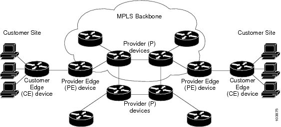
These are the basic components of MPLS VPN:

  • Provider (P) router—Router in the core of the provider network. P routers run MPLS switching and do not attach VPN labels to routed packets. VPN labels are used to direct data packets to the correct private network or customer edge router.

  • PE router—Router that attaches the VPN label to incoming packets based on the interface or sub-interface on which they are received, and also attaches the MPLS core labels. A PE router attaches directly to a CE router.

  • Customer (C) router—Router in the Internet service provider (ISP) or enterprise network.

  • Customer edge (CE) router—Edge router on the network of the ISP that connects to the PE router on the network. A CE router must interface with a PE router.

MPLS L3VPN Benefits

MPLS L3VPN provides the following benefits:

  • Service providers can deploy scalable VPNs and deliver value-added services.

  • Connectionless service guarantees that no prior action is necessary to establish communication between hosts.

  • Centralized Service: Building VPNs in Layer 3 permits delivery of targeted services to a group of users represented by a VPN.

  • Scalability: Create scalable VPNs using connection-oriented and point-to-point overlays.

  • Security: Security is provided at the edge of a provider network (ensuring that packets received from a customer are placed on the correct VPN) and in the backbone.

  • Integrated Quality of Service (QoS) support: QoS provides the ability to address predictable performance and policy implementation and support for multiple levels of service in an MPLS VPN.

  • Straightforward Migration: Service providers can deploy VPN services using a straightforward migration path.

  • Migration for the end customer is simplified. There is no requirement to support MPLS on the CE router and no modifications are required for a customer intranet.

Major Components of MPLS L3VPN—Details

An MPLS-based VPN network has three major components:

  • VPN route target communities—A VPN route target community is a list of all members of a VPN community. VPN route targets need to be configured for each VPN community member.

  • Multiprotocol BGP (MP-BGP) peering of the VPN community PE routers—MP-BGP propagates VRF reachability information to all members of a VPN community. MP-BGP peering needs to be configured in all PE routers within a VPN community.

  • MPLS forwarding—MPLS transports all traffic between all VPN community members across a VPN service-provider network.

A one-to-one relationship does not necessarily exist between customer sites and VPNs. A given site can be a member of multiple VPNs. However, a site can associate with only one VRF. A customer-site VRF contains all the routes available to the site from the VPNs of which it is a member.

Virtual Routing and Forwarding Tables

Each VPN is associated with one or more VPN routing and forwarding (VRF) instances. A VRF defines the VPN membership of a customer site attached to a PE router. A VRF consists of the following components:

  • An IP version 4 (IPv4) unicast routing table

  • A derived FIB table

  • A set of interfaces that use the forwarding table

  • A set of rules and routing protocol parameters that control the information that is included in the routing table

These components are collectively called a VRF instance.

A one-to-one relationship does not necessarily exist between customer sites and VPNs. A site can be a member of multiple VPNs. However, a site can associate with only one VRF. A VRF contains all the routes available to the site from the VPNs of which it is a member.

Packet forwarding information is stored in the IP routing table and the FIB table for each VRF. A separate set of routing and FIB tables is maintained for each VRF. These tables prevent information from being forwarded outside a VPN and also prevent packets that are outside a VPN from being forwarded to a router within the VPN.

VPN Routing Information: Distribution

The distribution of VPN routing information is controlled through the use of VPN route target communities, implemented by BGP extended communities. VPN routing information is distributed as follows:

  • When a VPN route that is learned from a CE router is injected into a BGP, a list of VPN route target extended community attributes is associated with it. Typically, the list of route target community extended values is set from an export list of route targets associated with the VRF from which the route was learned.

  • An import list of route target extended communities is associated with each VRF. The import list defines route target extended community attributes that a route must have for the route to be imported into the VRF. For example, if the import list for a particular VRF includes route target extended communities A, B, and C, then any VPN route that carries any of those route target extended communities—A, B, or C—is imported into the VRF.

BGP Distribution of VPN Routing Information

A PE router can learn an IP prefix from the following sources:

  • A CE router by static configuration

  • An eBGP session with the CE router

  • Open Shortest Path First (OSPF) as Interior Gateway Protocol (IGP)

The IP prefix is a member of the IPv4 address family. After the PE router learns the IP prefix, the PE converts it into the VPN-IPv4 prefix by combining it with a 64-bit route distinguisher. The generated prefix is a member of the VPN-IPv4 address family. It uniquely identifies the customer address, even if the customer site is using globally nonunique (unregistered private) IP addresses. The route distinguisher used to generate the VPN-IPv4 prefix is specified by the rd command associated with the VRF on the PE router.

BGP distributes reachability information for VPN-IPv4 prefixes for each VPN. BGP communication takes place at two levels:

  • Internal BGP (iBGP)—within the IP domain, known as an autonomous system.

  • External BGP (eBGP)—between autonomous systems.

BGP propagates reachability information for VPN-IPv4 prefixes among PE routers by the BGP protocol extensions (see RFC 2283, Multiprotocol Extensions for BGP-4), which define support for address families other than IPv4. Using the extensions ensures that the routes for a given VPN are learned only by other members of that VPN, enabling members of the VPN to communicate with each other.

MPLS Forwarding

Based on routing information stored in the VRF IP routing table and the VRF FIB table, packets are forwarded to their destination using MPLS.

A PE router binds a label to each customer prefix learned from a CE router and includes the label in the network reachability information for the prefix that it advertises to other PE routers. When a PE router forwards a packet received from a CE router across the provider network, it labels the packet with the label learned from the destination PE router. When the destination PE router receives the labeled packet, it pops the label and uses it to direct the packet to the correct CE router. Label forwarding across the provider backbone is based on dynamic label switching. A customer data packet carries two levels of labels when traversing the backbone:

  • The top label directs the packet to the correct PE router.

  • The second label indicates how that PE router should forward the packet to the CE router.

Automatic Route Distinguisher Assignment

To take advantage of iBGP load balancing, every network VRF must be assigned a unique route distinguisher. VRF is require a route distinguisher for BGP to distinguish between potentially identical prefixes received from different VPNs.

With thousands of routers in a network each supporting multiple VRFs, configuration and management of route distinguishers across the network can present a problem. Cisco IOS XR software simplifies this process by assigning unique route distinguisher to VRFs using the rd auto command.

To assign a unique route distinguisher for each router, you must ensure that each router has a unique BGP router-id. If so, the rd auto command assigns a Type 1 route distinguisher to the VRF using the following format: ip-address:number. The IP address is specified by the BGP router-id statement and the number (which is derived as an unused index in the 0 to 65535 range) is unique across theVRFs.

Finally, route distinguisher values are checkpointed so that route distinguisher assignment to VRF is persistent across failover or process restart. If an route distinguisher is explicitely configured for a VRF, this value is not overridden by the autoroute distinguisher.

Prerequisites for Implementing MPLS L3VPN

These are the prerequisites to configure MPLS L3VPN:

  • You must be in a user group associated with a task group that includes the proper task IDs for these commands:

      • BGP

      • IGP

      • MPLS

      • MPLS Layer 3 VPN

  • If you suspect user group assignment is preventing you from using a command, contact your AAA administrator for assistance.

  • To configure MPLS Layer 3 VPNs, routers must support MPLS forwarding and Forwarding Information Base (FIB).

Restrictions for MPLS L3VPN

Implementing MPLS L3VPN is subjected to these restrictions:

  • Fragmentation of MPLS packets that exceed egress MTU is not supported. Fragmentation is not supported for IP->MPLS imposition as well. Hence, it is recommended to use Maximum MTU (9216) value on all interfaces in the MPLS core.

  • L3VPN prefix lookup always yields a single path. In case of multiple paths at IGP or BGP level, path selection at each level is done using flow hash computed in data plane.

  • Per VRF aggregate statistics are not supported.

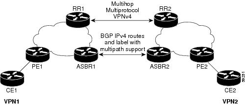
MPLS VPN Inter-AS with ASBRs exchanging IPv4 routes and MPLS labels

  • For networks configured with eBGP multihop, a label switched path (LSP) must be configured between non adjacent routers.

  • Layer 3 VPN over SR-TE is not supported.

Label assignments

  • Local label allocation for every VRF on MPLS VPN.

  • One VPN label for every VRF.

  • Must have per VRF label mode across the VRF deployment.

Configure the Core Network

Consider a network topology where MPLS L3VPN services are transported over MPLS LDP core.

Figure 2. L3VPN over MPLS LDP

Configuring the core network involves these main tasks:

  • Assess the Needs of MPLS VPN Customers

  • Configure Routing Protocols in the Core

  • Configure MPLS in the Core

  • Determine if FIB is Enabled in the Core

  • Configure Multiprotocol BGP on the PE Routers and Route Reflectors

Assess the Needs of MPLS VPN Customers

Before configuring an MPLS VPN, the core network topology must be identified so that it can best serve MPLS VPN customers. The tasks listed below helps to identify the core network topology.

  • Identify the size of the network:

    Identify the following to determine the number of routers and ports required:

    • How many customers to be supported?

    • How many VPNs are required for each customer?

    • How many virtual routing and forwarding (VRF) instances are there for each VPN?

  • Determine the routing protocols required in the core.

  • Determine if BGP load sharing and redundant paths in the MPLS VPN core are required.

Configure Routing Protocols in the Core

You can use OSPF or IS-IS as the routing protocol in the core.

Figure 3. OSPF as Routing Protocol in the Core


Configuration Example

This example lists the steps to configure OSPF as the routing protocol in the core.


Router-PE1#configure
Router-PE1(config)#router ospf dc-core
Router-PE1(config-ospf)#address-family ipv4 unicast
Router-PE1(config-ospf)#area 1
Router-PE1(config-ospf-ar)#interface HundredGigE0/0/0/2
Router-PE1(config-ospf-vrf-ar-if)#commit

Running Configuration


router ospf dc-core
 router-id 13.13.13.1
 address-family ipv4 unicast
 area 1
  interface HundredGigE0/0/0/2
    
  !
 !
!

Verification

Verify the OSPF neighbor and ensure that the State is displayed as 'FULL'.


Router-PE1# show ospf neighbor
Neighbors for OSPF dc-core

Neighbor ID     Pri   State           Dead Time   Address         Interface
16.16.16.1      1     FULL/DR  00:00:34    191.22.1.2      HundredGigE0/0/0/2
    Neighbor is up for 1d18h

Total neighbor count: 1

Configure MPLS in the Core

You can also transport MPLS L3VPN services using segment routing in the core. For details, see .

Configuration Example

This example lists the steps to configure LDP in MPLS core.


Router-PE1#configure
Router-PE1(config)#mpls ldp
Router-PE1(config-ldp)#router-id 13.13.13.1
Router-PE1(config-ldp)#address-family ipv4
Router-PE1(config-ldp-af)#exit
Router-PE1(config-ldp)#interface HundredGigE0/0/0/2
Router-PE1(config-ldp)#commit

Repeat this configuration in PE2 and P routers as well.

Running Configuration


mpls ldp
 router-id 13.13.13.1
 address-family ipv4
 !
 interface HundredGigE0/0/0/2
 
 
 !
!

Verification

Verify that the neighbor (16.16.16.1) is UP through the core interface:


Router-PE1#show mpls ldp neighbor
Peer LDP Identifier: 16.16.16.1:0
  TCP connection: 16.16.16.1:47619 - 13.13.13.1:646
  Graceful Restart: No
  Session Holdtime: 180 sec
  State: Oper; Msgs sent/rcvd: 40395/35976; Downstream-Unsolicited
  Up time: 2w2d
  LDP Discovery Sources:
    IPv4: (1)
      HundredGigE0/0/0/2
    IPv6: (0)
  Addresses bound to this peer:
    IPv4: (6)
      10.64.98.32    87.0.0.2       88.88.88.14    50.50.50.50     
      178.0.0.1      192.168.0.1      
    IPv6: (0)

Determine if FIB is Enabled in the Core

Forwarding Information Base (FIB) must be enabled on all routers in the core, including the provider edge (PE) routers. For information on how to determine if FIB is enabled, see the Implementing Cisco Express Forwarding module in the IP Addresses and Services Configuration Guide for Cisco 8000 Series Routers.

Configure Multiprotocol BGP on the PE Routers and Route Reflectors

Multiprotocol BGP (MP-BGP) propagates VRF reachability information to all members of a VPN community. You must configure MP-BGP peering in all the PE routers within a VPN community.

Figure 4. Multiprotocol BGP on PE Routers

Configuration Example

This example shows how to configure MP-BGP on PE1. The loopback address (20.20.20.1) of PE2 is specified as the neighbor of PE1. Similarly, you must perform this configuration on PE2 node as well, with the loopback address (13.13.13.1) of PE1 specified as the neighbor of PE2.


Router-PE1#configure
Router-PE1(config)#router bgp 2001
Router-PE1(config-bgp)#bgp router-id 10.0.0.1
Router-PE1(config-bgp)#address-family ipv4 unicast
Router-PE1(config-bgp-af)#exit
Router-PE1(config-bgp)#address-family vpnv4 unicast
Router-PE1(config-bgp-af)#exit
Router-PE1(config-bgp)#neighbor 172.16.0.1
Router-PE1(config-bgp-nbr)#remote-as 2001
Router-PE1(config-bgp-nbr)#update-source loopback 0
Router-PE1(config-bgp-nbr)#address-family ipv4 unicast
Router-PE1(config-bgp-nbr-af)#exit
Router-PE1(config-bgp-nbr)#address-family vpnv4 unicast
Router-PE1(config-bgp-nbr-af)#exit
Router-PE1(config-bgp-nbr)#exit
/* VRF configuration */
Router(config-bgp)# vrf vrf1601
Router-PE1(config-bgp-vrf)#rd 2001:1601
Router-PE1(config-bgp-vrf)#address-family ipv4 unicast
Router-PE1(config-bgp-vrf-af)#label mode per-vrf
Router-PE1(config-bgp-vrf-af)#redistribute connected
Router-PE1(config-bgp-vrf-af)#commit

Running Configuration


router bgp 2001
 bgp router-id 10.0.0.1
 address-family ipv4 unicast
 !
 address-family vpnv4 unicast
 !
 neighbor 172.16.0.1
  remote-as 2001
  update-source Loopback0
  address-family vpnv4 unicast
  !
  address-family ipv4 unicast
  !
 !
 vrf vrf1601
  rd 2001:1601
  address-family ipv4 unicast
   label mode per-vrf
   redistribute connected
  !
 !

Verification

  • Verify if the BGP state is established, and if the Remote AS and local AS displays the same value (2001 in this example):

    
    Router-PE1#show bgp neighbor
    
    BGP neighbor is 172.16.0.1
     Remote AS 2001, local AS 2001, internal link
     Remote router ID 172.16.0.1
      BGP state = Established, up for 1d19h
      NSR State: None
      Last read 00:00:04, Last read before reset 00:00:00
      Hold time is 60, keepalive interval is 20 seconds
      Configured hold time: 60, keepalive: 30, min acceptable hold time: 3
      Last write 00:00:16, attempted 19, written 19
      Second last write 00:00:36, attempted 19, written 19
      Last write before reset 00:00:00, attempted 0, written 0
      Second last write before reset 00:00:00, attempted 0, written 0
      Last write pulse rcvd  Apr 12 10:31:20.739 last full not set pulse count 27939
      Last write pulse rcvd before reset 00:00:00
      Socket not armed for io, armed for read, armed for write
      Last write thread event before reset 00:00:00, second last 00:00:00
      Last KA expiry before reset 00:00:00, second last 00:00:00
      Last KA error before reset 00:00:00, KA not sent 00:00:00
      Last KA start before reset 00:00:00, second last 00:00:00
      Precedence: internet
      Non-stop routing is enabled
      Multi-protocol capability received
      Neighbor capabilities:
        Route refresh: advertised (old + new) and received (old + new)
        Graceful Restart (GR Awareness): received
        4-byte AS: advertised and received
        Address family IPv4 Unicast: advertised and received
        Address family VPNv4 Unicast: advertised and received
      Received 25595 messages, 0 notifications, 0 in queue
      Sent 8247 messages, 0 notifications, 0 in queue
      Minimum time between advertisement runs is 0 secs
      Inbound message logging enabled, 3 messages buffered
      Outbound message logging enabled, 3 messages buffered
    
     For Address Family: IPv4 Unicast
      BGP neighbor version 484413
      Update group: 0.4 Filter-group: 0.3  No Refresh request being processed
      Inbound soft reconfiguration allowed
      NEXT_HOP is always this router
      AF-dependent capabilities:
        Outbound Route Filter (ORF) type (128) Prefix:
          Send-mode: advertised, received
          Receive-mode: advertised, received
        Graceful Restart capability received
          Remote Restart time is 120 seconds
          Neighbor did not preserve the forwarding state during latest restart
        Additional-paths Send: advertised and received
        Additional-paths Receive: advertised and received
      Route refresh request: received 1, sent 1
      Policy for incoming advertisements is pass-all
      Policy for outgoing advertisements is pass-all
      24260 accepted prefixes, 24260 are bestpaths
      Cumulative no. of prefixes denied: 0. 
      Prefix advertised 2000, suppressed 0, withdrawn 0
      Maximum prefixes allowed 1048576
      Threshold for warning message 75%, restart interval 0 min
      AIGP is enabled
      An EoR was received during read-only mode
      Last ack version 484413, Last synced ack version 0
      Outstanding version objects: current 0, max 1
      Additional-paths operation: Send and Receive
      Send Multicast Attributes
      Advertise VPNv4 routes enabled with defaultReoriginate,disable Local with stitching-RT option
    
     For Address Family: VPNv4 Unicast
      BGP neighbor version 798487
      Update group: 0.2 Filter-group: 0.1  No Refresh request being processed
      AF-dependent capabilities:
        Graceful Restart capability received
          Remote Restart time is 120 seconds
          Neighbor did not preserve the forwarding state during latest restart
        Additional-paths Send: advertised and received
        Additional-paths Receive: advertised and received
      Route refresh request: received 0, sent 0
      29150 accepted prefixes, 29150 are bestpaths
      Cumulative no. of prefixes denied: 0. 
      Prefix advertised 7200, suppressed 0, withdrawn 0
      Maximum prefixes allowed 2097152
      Threshold for warning message 75%, restart interval 0 min
      AIGP is enabled
      An EoR was received during read-only mode
      Last ack version 798487, Last synced ack version 0
      Outstanding version objects: current 0, max 1
      Additional-paths operation: Send and Receive
      Send Multicast Attributes
      Advertise VPNv4 routes enabled with defaultReoriginate,disable Local with stitching-RT option
    
      Connections established 1; dropped 0
      Local host: 10.0.0.1, Local port: 35018, IF Handle: 0x00000000
      Foreign host: 172.16.0.1, Foreign port: 179
      Last reset 00:00:00
    
    
  • Verify if all the IP addresses are learnt on PE1 from PE2:

    
    Router-PE1#show bgp vpnv4 unicast
    
    BGP router identifier 10.0.0.1, local AS number 2001
    BGP generic scan interval 60 secs
    Non-stop routing is enabled
    BGP table state: Active
    Table ID: 0x0   RD version: 0
    BGP main routing table version 798487
    BGP NSR Initial initsync version 15151 (Reached)
    BGP NSR/ISSU Sync-Group versions 0/0
    BGP scan interval 60 secs
    
    Status codes: s suppressed, d damped, h history, * valid, > best
                  i - internal, r RIB-failure, S stale, N Nexthop-discard
    Origin codes: i - IGP, e - EGP, ? - incomplete
       Network            Next Hop            Metric LocPrf Weight Path
    Route Distinguisher: 2001:1601 (default for vrf vrf1601)
    *> 172.16.0.1/12       192.168.0.1                            0 7501 i
    *> 172.16.0.1/12       192.168.0.2                            0 7501 i
    *> 172.16.0.3/12       192.168.0.3                            0 7501 i
    *> 172.16.0.4/12       192.168.0.4                            0 7501 i
    *> 172.16.0.5/12       192.168.0.5                            0 7501 i
    *>i172.16.0.1/1210.0.0.1                    100      0 8501 i
    *>i172.16.0.2/1210.0.0.1                    100      0 8501 i
    *>i172.16.0.3/1210.0.0.1                    100      0 8501 i
    *>i172.16.0.4/1210.0.0.1                    100      0 8501 i
    *>i172.16.0.5/1210.0.0.1                    100      0 8501 i


Verify MPLS L3VPN Configuration

You must verify these to ensure the successful configuration of MPLS L3VPN:

Verify the L3VPN Traffic Flow

P node:

Router-P#show mpls forwarding
Local  Outgoing    Prefix             Outgoing     Next Hop        Bytes       
Label  Label       or ID              Interface                    Switched    
------ ----------- ------------------ ------------ --------------- ------------
24119  Pop         20.20.20.1/32      Hu0/0/0/0    191.31.1.90     2170204180148

PE2:

Router#show mpls forwarding
Local  Outgoing    Prefix             Outgoing     Next Hop        Bytes       
Label  Label       or ID              Interface                    Switched   
------ ----------- ------------------ ------------ --------------- ------------ 
24031  Aggregate   vrf1601: Per-VRF Aggr[V]   \
                                      vrf1601                      0

Verify the Underlay (transport)

Verify if the LDP neighbor connection is established with the respective neighbor:

Router-PE1#show mpls ldp neighbor
Peer LDP Identifier: 16.16.16.1:0
  TCP connection: 16.16.16.1:47619 - 13.13.13.1:646
  Graceful Restart: No
  Session Holdtime: 180 sec
  State: Oper; Msgs sent/rcvd: 40395/35976; Downstream-Unsolicited
  Up time: 2w2d
  LDP Discovery Sources:
    IPv4: (1)
      TenGigE0/0/0/2
    IPv6: (0)
  Addresses bound to this peer:
    IPv4: (6)
      10.64.98.32    87.0.0.2       88.88.88.14    50.50.50.50     
      178.0.0.1      192.1.1.1      
    IPv6: (0)

Verify if the label update is received by the FIB:

Router-PE1#show mpls forwarding
Local  Outgoing    Prefix             Outgoing     Next Hop        Bytes       
Label  Label       or ID              Interface                    Switched    
------ ----------- ------------------ ------------ --------------- ------------    
24036  Pop         16.16.16.1/32      Hu0/0/0/2    191.22.1.2      293294               
24037  24165       18.18.18.1/32      Hu0/0/0/2    191.22.1.2      500                   
24039  24167       20.20.20.1/32      Hu0/0/0/2    191.22.1.2      17872433
	      24167	      20.20.20.1/32	     Hu0/0/0/2.1  191.22.3.2	     6345              
24041  Aggregate   vrf1601: Per-VRF Aggr[V]   \
                                      vrf1601                      0  

Verify if label is updated in the hardware:

Router-PE1#show mpls forwarding labels 24001 hardware egress

Local  Outgoing    Prefix             Outgoing     Next Hop        Bytes       
Label  Label       or ID              Interface                    Switched    
------ ----------- ------------------ ------------ --------------- ------------
24039  24167       20.20.20.1/32      Hu0/0/0/2    191.22.1.2      N/A         
	   24167	   20.20.20.1/32	  Hu0/0/0/2.1  191.22.3.2	   N/A

 Show-data Print at RPLC 
 
 LEAF - HAL pd context : 
 sub-type : MPLS, ecd_marked:0, has_collapsed_ldi:0
 collapse_bwalk_required:0, ecdv2_marked:0

Leaf H/W Result:

Leaf H/W Result on NP:0
Label           SwitchAction      EgressIf      Programmed
24039                      0    0x    200185    Programmed

nrLDI eng ctx:
     flags: 0x101, proto: 2, npaths: 0, nbuckets: 1
    ldi_tbl_idx: 0xc37e40, ecd_ref_cft: 0
    pbts_ldi_tbl_idx: 0x0, fastnrldi:0x0 

NR-LDI H/W Result for path 0 [index: 0xc37e40 (BE),  common to all NPs]:
          
 ECMP Sw Idx: 12811840 HW Idx: 200185 Path Idx: 0

NR-LDI H/W Result for path 1 [index: 0xc37e41 (BE),  common to all NPs]:

 ECMP Sw Idx: 12811841 HW Idx: 200185 Path Idx: 1

SHLDI eng ctx:
    flags: 0x0, shldi_tbl_idx: 0, num_entries:0

SHLDI HW data for path 0 [index: 0 (BE)] (common to all NPs):
Unable to get HW NRLDI Element rc: 1165765120NRLDI Idx: 0
SHLDI HW data for path 1 [index: 0x1 (BE)] (common to all NPs):
Unable to get HW NRLDI Element rc: 1165765120NRLDI Idx: 1

TX H/W Result for NP:0 (index: 0x187a0 (BE)):

 Next Hop Data
 Next Hop Valid:         YES
 Next Hop Index:         100256
 Egress Next Hop IF:     100047
 Hw Next Hop Intf:       606
 HW Port:                0
 Next Hop Flags:         COMPLETE 
 Next Hop MAC:           e4aa.5d9a.5f2e

NHINDEX H/W Result for NP:0 (index: 0 (BE)):
NhIndex is NOT required on this platform

NHINDEX STATS: pkts 0, bytes 0 (no stats)

RX H/W Result on NP:0 [Adj ptr:0x40 (BE)]:
Rx-Adj is NOT required on this platform

TX H/W Result for NP:0 (index: 0x189a8 (BE)):

 Next Hop Data
 Next Hop Valid:         YES
 Next Hop Index:         100776
 Egress Next Hop IF:     100208
 Hw Next Hop Intf:       607
 HW Port:                0
 Next Hop Flags:         COMPLETE 
 Next Hop MAC:           e4aa.5d9a.5f2d

NHINDEX H/W Result for NP:0 (index: 0 (BE)):
NhIndex is NOT required on this platform

NHINDEX STATS: pkts 0, bytes 0 (no stats)

RX H/W Result on NP:0 [Adj ptr:0x40 (BE)]:
Rx-Adj is NOT required on this platform

Verify the Overlay (L3VPN)

Imposition Path: Verify if the BGP neighbor connection is established with the respective neighbor node:

Router-PE1#show bgp summary
BGP router identifier 13.13.13.1, local AS number 2001
BGP generic scan interval 60 secs
Non-stop routing is enabled
BGP table state: Active
Table ID: 0xe0000000   RD version: 18003
BGP main routing table version 18003
BGP NSR Initial initsync version 3 (Reached)
BGP NSR/ISSU Sync-Group versions 0/0
BGP scan interval 60 secs

BGP is operating in STANDALONE mode.

Process       RcvTblVer   bRIB/RIB   LabelVer  ImportVer  SendTblVer  StandbyVer
Speaker           18003      18003      18003      18003       18003           0

Neighbor        Spk    AS MsgRcvd MsgSent   TblVer  InQ OutQ  Up/Down  St/PfxRcd
21.21.21.1        0  2001   19173    7671    18003    0    0    1d07h       4000
192.13.2.149      0  7001    4615    7773    18003    0    0 09:26:21        125

Verify if BGP routes are advertised and learnt:

Router-PE1#show bgp vpnv4 unicast
BGP router identifier 13.13.13.1, local AS number 2001
BGP generic scan interval 60 secs
Non-stop routing is enabled
BGP table state: Active
Table ID: 0x0   RD version: 0
BGP main routing table version 305345
BGP NSR Initial initsync version 12201 (Reached)
BGP NSR/ISSU Sync-Group versions 0/0
BGP scan interval 60 secs

Status codes: s suppressed, d damped, h history, * valid, > best
              i - internal, r RIB-failure, S stale, N Nexthop-discard
Origin codes: i - IGP, e - EGP, ? - incomplete
   Network            Next Hop            Metric LocPrf Weight Path
Route Distinguisher: 2001:1601 (default for vrf vrf1601)
*> 20.13.1.1/32       192.13.26.5                            0 7501 i
*> 20.13.1.2/32       192.13.26.5                            0 7501 i
*>i20.23.1.1/32       20.20.20.1                    100      0 6553700 11501 i
*>i20.23.1.2/32       20.20.20.1                    100      0 6553700 11501 i

Verify BGP labels:

Router-PE1#show bgp label table
Label   Type               VRF/RD         Context
24041   IPv4 VRF Table   vrf1601          -
24042   IPv4 VRF Table   vrf1602          -

Verify if the route is downloaded in the respective VRF:

Router-PE1#show cef vrf vrf1601 20.23.1.1
20.23.1.1/32, version 743, internal 0x5000001 0x0 (ptr 0x8f932174) [1], 0x0 (0x8fa99990), 0xa08 (0x8f9fba58)
 Updated Apr 20 12:33:47.840
 Prefix Len 32, traffic index 0, precedence n/a, priority 3
   via 20.20.20.1/32, 3 dependencies, recursive [flags 0x6000]
    path-idx 0 NHID 0x0 [0x8c0e3148 0x0]
    recursion-via-/32
    next hop VRF - 'default', table - 0xe0000000
    next hop 20.20.20.1/32 via 24039/0/21
    next hop 191.23.1.2/32 Hu0/0/1/1    labels imposed {24059 24031}

Disposition Path

Verify if the imposition and disposition labels are assigned and label bindings are exchanged for L3VPN prefixes:


Router-PE2#show mpls lsd forwarding
In_Label, (ID), Path_Info: <Type>
24030, (IPv4, 'default':4U, 13.13.13.1/32), 5 Paths
   1/1: IPv4, 'default':4U, Hu0/0/0/19.2, nh=191.31.1.93, lbl=24155,
            flags=0x0, ext_flags=0x0 
24031, (VPN-VRF, 'vrf1601':4U), 1 Paths
   1/1: PopLkup-v4, 'vrf1601':4U, ipv4 
24032, (VPN-VRF, 'vrf1602':4U), 1 Paths
   1/1: PopLkup-v4, 'vrf1602':4U, ipv4 

Verify if the label update is received by the FIB:

Router-PE2#show mpls forwarding
Local  Outgoing    Prefix             Outgoing     Next Hop        Bytes       
Label  Label       or ID              Interface                    Switched    
------ ----------- ------------------ ------------ --------------- ------------         
24019  Pop         18.18.18.3/32      Hu0/0/0/19   191.31.1.89     11151725032                   
24030  24155       13.13.13.1/32      Hu0/0/0/19   191.31.1.89     3639895                  
24031  Aggregate   vrf1601: Per-VRF Aggr[V]   \
                                     vrf1601                       0 

L3VPN over RSVP-TE

Table 1. Feature History Table

Feature Name

Release Information

Feature Description

L3VPN over RSVP-TE

Release 7.3.2

Using labeled switch paths (LSPs), this feature enables resource reservations in each node across data paths on MPLS-configured Layer 3 VPNs. Such reservations allow service providers to offer high throughput to their subscribers with optimal network operations.

MPLS Traffic Engineering (MPLS-TE) learns the topology and resources available in a network and then maps traffic flows to particular paths based on network resources. MPLS TE builds a unidirectional tunnel from a source to a destination in the form of a label switched path (LSP), which is then used to forward traffic. MPLS-TE uses RSVP to signal LSPs.

RSVP processes protocol messages from other systems, processes resource requests from local clients, and generates protocol messages. As a result, resources are reserved for data flows on behalf of local and remote clients. RSVP creates, maintains, and deletes these resource reservations. RSVP is automatically enabled on interfaces on which MPLS-TE is configured.

For more information on RSVP-TE and MPLS-TE, see the MPLS Configuration Guide for Cisco 8000 Series Routers.

Configure L3VPN over RSVP-TE

Perform these steps to configure L3VPN over RSVP-TE:

  • Configure routing protocols in the core—To configure routing protocols in the core, see the Routing Configuration Guide for Cisco 8000 Series Routers.

  • Enable MPLS on all routers in the core—To enable MPLS on all routers in the core, you must configure a Label Distribution Protocol (LDP). You can use either of the following as an LDP:

    • MPLS LDP—See the Implementing MPLS Label Distribution Protocol chapter in the MPLS Configuration Guide for Cisco 8000 Series Routers for configuration information.

    • MPLS Traffic Engineering Resource Reservation Protocol (RSVP)—See the Implementing RSVP for MPLS-TE chapter in the MPLS Configuration Guide for Cisco 8000 Series Routers for configuration information.

VRF-lite

VRF-lite is the deployment of VRFs without MPLS. VRF-lite allows a service provider to support two or more VPNs with overlapping IP addresses. With this feature, multiple VRF instances can be supported in customer edge devices.

VRF-lite interfaces must be Layer 3 interface and this interface cannot belong to more than one VRF at any time. Multiple interfaces can be part of the same VRF, provided all of them participate in the same VPN.

Configure VRF-lite

Consider two customers having two VPN sites each, that are connected to the same PE router. VRFs are used to create a separate routing table for each customer. We create one VRF for each customer (say, vrf1 and vrf2) and then add the corresponding interfaces of the router to the respective VRFs. Each VRF has its own routing table with the interfaces configured under it. The global routing table of the router does not show these interfaces, whereas the VRF routing table shows the interfaces that were added to the VRF. PE routers exchange routing information with CE devices by using static routing or a routing protocol such as BGP or OSPF.

To summarize, VRF-lite configuration involves these main tasks:

  • Create VRF

  • Configure VRF under the interface

  • Configure VRF under routing protocol

Configuration Example

  • Create VRF:

    
    Router#configure
    Router(config)#vrf vrf1
    Router(config-vrf)#address-family ipv4 unicast
    /* You must create route-policy pass-all before this configuration */
    Router(config-vrf-af)#import from default-vrf route-policy pass-all
    Router(config-vrf-af)#import route-target
    Router(config-vrf-import-rt)#100:100
    Router(config-vrf-import-rt)#exit
    Router(config-vrf-af)#export route-target
    Router(config-vrf-import-rt)#100:100
    Router(config-vrf-import-rt)#exit
    Router(config-vrf-import-rt)#commit


    Similarly create vrf2, with route-target as 100:100.

  • Configure VRF under the interface:

    
    Router#configure
    Router(config-subif)#interface TenGigE0/0/0/0.2001
    Router(config-subif)#ipv4 address 192.0.2.2 255.255.255.252
    Router(config-subif)#encapsulation dot1q 2001
    Router(config-subif)#exit
    
    Router(config)#interface TenGigE0/0/0/0.2000
    Router(config-subif)#vrf vrf2
    Router(config-subif)#ipv4 address 192.0.2.5/30 255.255.255.252
    Router(config-subif)#encapsulation dot1q 2000
    Router(config-vrf-import-rt)#commit


    Similarly configure vrf1 under interface TenGigE0/0/0/1.2001 and vrf2 under interface TenGigE0/0/0/1.2000

  • Configure VRF under routing protocol:

    
    Router#configure
    Router(config)#router ospf 100 area 0
    Router(config-ospf-ar)#interface loopback 0
    Router(config-ospf-ar-if)#exit
    Router(config-ospf-ar)#interface TenGigE0/0/0/1
    Router(config-ospf-ar-if)#exit
    Router(config-ospf-ar)#interface TenGigE0/0/0/1.2001
    Router(config-ospf-ar-if)#vrf vrf1
    Router(config-ospf-vrf)#default-information originate
    Router(config-ospf-vrf)#exit
    Router(config-ospf)#exit
    Router(config)#router ospf 100 area 0
    Router(config-ospf-ar)#interface TenGigE0/0/0/1.2000
    Router(config-ospf-ar-if)#vrf vrf2
    Router(config-ospf-vrf)#default-information originate
    Router(config-ospf-vrf)#commit
    

Running Configuration


/* VRF Configuration */

vrf vrf1
address-family ipv4 unicast
  import route-target
   100:100
  !
  export route-target
   100:100
  !
!
!
vrf vrf2
address-family ipv4 unicast
  import route-target
   100:100
  !
  export route-target
   100:100
  !
!
!


/* Interface Configuration */

interface TenGigE0/0/0/0.2001
vrf vrf1
ipv4 address 192.0.2.2 255.255.255.252
encapsulation dot1q 2001
!

interface TenGigE0/0/0/0.2000
vrf vrf2
ipv4 address 192.0.2.5/30 255.255.255.252
encapsulation dot1q 2000
!

interface TenGigE0/0/0/1.2001
vrf vrf1
ipv4 address 203.0.113.2 255.255.255.252
encapsulation dot1q 2001
!

interface TenGigE0/0/0/1.2000
vrf vrf2
ipv4 address 203.0.113.5 255.255.255.252
encapsulation dot1q 2000
!

/* Routing Protocol Configuration */
router ospf 100 area 0
interface Loopback0
!

interface TenGigE0/0/0/1
!
interface TenGigE0/0/0/1.20001
 vrf vrf1
 default-information originate
  !

interface TenGigE0/0/0/1.2000
 vrf vrf2
 default-information originate
 !

Verification


Router#show route vrf vrf1
Mon Jul  4 19:12:54.739 UTC

Codes: C - connected, S - static, B - BGP, (>) - Diversion path
       O - OSPF, IA - OSPF inter area
       N1 - OSPF NSSA external type 1, N2 - OSPF NSSA external type 2
       E1 - OSPF external type 1, E2 - OSPF external type 2, E - EGP
       i - ISIS, L1 - IS-IS level-1, L2 - IS-IS level-2
       ia - IS-IS inter area, su - IS-IS summary null, * - candidate default
       U - per-user static route, o - ODR, L - local, G  - DAGR, l - LISP
       A - access/subscriber, a - Application route
       M - mobile route, r - RPL, (!) - FRR Backup path

Gateway of last resort is not set

C    203.0.113.0/24 is directly connected, 00:07:01, TenGigE0/0/0/1.2001
L    203.0.113.2/30 is directly connected, 00:07:01, TenGigE0/0/0/1.2001
C    192.0.2.0/24 is directly connected, 00:05:51, TenGigE0/0/0/1.2001
L    192.0.2.2/30 is directly connected, 00:05:51, TenGigE0/0/0/1.2001

Router#show route vrf vrf2
Mon Jul  4 19:12:59.121 UTC

Codes: C - connected, S - static, B - BGP, (>) - Diversion path
       O - OSPF, IA - OSPF inter area
       N1 - OSPF NSSA external type 1, N2 - OSPF NSSA external type 2
       E1 - OSPF external type 1, E2 - OSPF external type 2, E - EGP
       i - ISIS, L1 - IS-IS level-1, L2 - IS-IS level-2
       ia - IS-IS inter area, su - IS-IS summary null, * - candidate default
       U - per-user static route, o - ODR, L - local, G  - DAGR, l - LISP
       A - access/subscriber, a - Application route
       M - mobile route, r - RPL, (!) - FRR Backup path

Gateway of last resort is not set

R    198.51.100.53/30 [120/1] via 192.0.2.1, 00:01:42, TenGigE0/0/0/0.2000
C    203.0.113.0/24 is directly connected, 00:08:43, TenGigE0/0/0/1.2000
L    203.0.113.5/30 is directly connected, 00:08:43, TenGigE0/0/0/1.2000
C    192.0.2.0/24 is directly connected, 00:06:17, TenGigE0/0/0/0.2000
L    192.0.2.5/30 is directly connected, 00:06:17, TenGigE0/0/0/0.2000

MPLS L3VPN Services using Segment Routing

Currently, MPLS Label Distribution Protocol (LDP) is the widely used transport for MPLS L3VPN services. The user can achieve better resilience and convergence for the network traffic, by transporting MPLS L3VPN services using Segment Routing (SR), instead of MPLS LDP. Segment routing can be directly applied to the MPLS architecture without changing the forwarding plane. In a segment-routing network using the MPLS data plane, LDP or other signaling protocol is not required; instead label distribution is performed by IGP (IS-IS or OSPF) or BGP protocol. Removing protocols from the network simplifies its operation and makes it more robust and stable by eliminating the need for protocol interaction. Segment routing utilizes the network bandwidth more effectively than traditional MPLS networks and offers lower latency.

Configure MPLS L3VPN over Segment Routing

Topology

Given below is a network scenario, where MPLS L3VPN service is transported using Segment Routing.

Figure 5. MPLS L3VPN over Segment Routing

In this topology, CE1 and CE2 are the two customer routers. ISP has two PE routers, PE1 and PE2 and a P router. OSPF is used for the edge protocol support between the CE and PE routers. Label distribution can be performed by IGP (IS-IS or OSPF) or BGP. OSPF is used in this scenario.

Customer's autonomous system is 65534, which peers with ISP's autonomous system 65000. This must be a vrf peering to prevent route advertisement into the global IPv4 table. The ISP routers PE1 and PE2 contain the VRF (for example, vrf1601) for the customer. PE1 and PE2 export and import the same route targets, although this is not necessary.

Loopback interfaces are used in this topology to simulate the attached networks.

Configuration

You must complete these tasks to ensure the successful configuration of MPLS L3VPN over segment routing:

  • Configure Segment Routing in MPLS Core

  • Configure protocol support on PE-CE (see Connect MPLS VPN Customers)

  • Configure protocol support on PE-PE (see Configure Multiprotocol BGP on the PE Routers and Route Reflectors)

Configure Segment Routing in MPLS Core

This section takes you through the configuration procedure to enable segment routing in MPLS core. You must perform this configuration in PE1, P and PE2 routers in the topology, using the corresponding values.

Configuration Example


/* Configure Segment Routing using OSFP */

Router-PE1#configure
Router-PE1(config)# router ospf dc-sr
Router-PE1(config-ospf)#router-id 13.13.13.1
Router-PE1(config-ospf)#segment routing mpls
Router-PE1(config-ospf)#segment routing forwarding mpls
Router-PE1(config-ospf)#mpls ldp sync
Router-PE1(config-ospf)#mpls ldp auto-config
Router-PE1(config-ospf)#segment-routing sr-prefer
Router-PE1(config-ospf)#segment-routing prefix-sid-map advertise-local
Router-PE1(config-ospf)#exit
Router-PE1(config-ospf)#area 1
Router-PE1(config-ospf-ar)#interface HundredGigE0/0/0/2
Router-PE1(config-ospf-ar-if)#exit
Router-PE1(config-ospf-ar)#interface Loopback0
Router-PE1(config-ospf-ar-if)#prefix-sid index 1
Router-PE1(config-ospf-ar-if)#commit

/ * Configure segment routing global block */

Router# configure
Router(config)# segment-routing
Router(config-sr)# global-block 180000 200000
Router(config-sr)# commit
Router(config-sr)# exit


/* Configure Segment Routing using ISIS */

Router# configure
Router(config)# router isis ring
Router(config-isis)# is-type level-2-only
Router(config-isis)# net 49.0001.1921.6800.1001.00
Router(config-isis)# nsr
Router(config-isis)# distribute link-state
Router(config-isis)# nsf cisco
Router(config-isis)# address-family ipv4 unicast
Router(config-isis-af)# metric-style wide
Router(config-isis-af)# mpls traffic-eng level-1
Router(config-isis-af)# mpls traffic-eng router-id loopback0
Router(config-isis-af)# segment-routing mpls sr-prefer
Router(config-isis-af)# exit
!
Router(config-isis)# interface loopback0
Router(config-isis-if)# address-family ipv4 unicast
Router(config-isis-af)# prefix-sid index 30101
Router(config-isis-af)# exit

Running Configuration

PE1:


router ospf dc-sr
 router-id 13.13.13.1
 segment-routing mpls
 segment-routing forwarding mpls
 mpls ldp sync
 mpls ldp auto-config
 segment-routing sr-prefer
 segment-routing prefix-sid-map receive
 segment-routing prefix-sid-map advertise-local
 !
 area 1
  interface HundredGigE0/0/0/2
  !
  interface Loopback0
   prefix-sid index 1
  !
 !
!

configure
 segment-routing
  global-block 180000 200000
 !
!

configure
 router isis ring
  net 49.0001.1921.6800.1001.00
  nsr
  distribute link-state
  nsf cisco
  address-family ipv4 unicast
   metric-style wide
   mpls traffic-eng level-1
   mpls traffic-eng router-id Loopback0
   segment-routing mpls sr-prefer
 !
 interface Loopback0
  address-family ipv4 unicast
   prefix-sid index 30101
  !
 !

P node:


router ospf dc-sr
 router-id 16.16.16.1
 segment-routing mpls
 segment-routing forwarding mpls
 mpls ldp sync
 mpls ldp auto-config
 segment-routing sr-prefer
 segment-routing prefix-sid-map receive
 segment-routing prefix-sid-map advertise-local
 !
 area 1
  interface HundredGigE0/0/1/0
  !
  interface HundredGigE0/0/1/1
  !
  interface Loopback0
   prefix-sid index 1
  !
 !
!

configure
 segment-routing
  global-block 180000 200000
 !
!

configure
 router isis ring
  net 49.0001.1921.6800.1002.00
  nsr
  distribute link-state
  nsf cisco
  address-family ipv4 unicast
   metric-style wide
   mpls traffic-eng level-1
   mpls traffic-eng router-id Loopback0
   segment-routing mpls sr-prefer
 !
 interface Loopback0
  address-family ipv4 unicast
   prefix-sid index 30102
  !
 !

PE2:


router ospf dc-sr
 router-id 20.20.20.1
 segment-routing mpls
 segment-routing forwarding mpls
 mpls ldp sync
 mpls ldp auto-config
 segment-routing sr-prefer
 segment-routing prefix-sid-map receive
 segment-routing prefix-sid-map advertise-local
 !
 area 0
  interface HundredGigE0/0/0/19
  !
  interface Loopback0
   prefix-sid index 1
  !
 !
!

configure
 segment-routing
  global-block 180000 200000
 !
!

configure
 router isis ring
  net 49.0001.1921.6800.1003.00
  nsr
  distribute link-state
  nsf cisco
  address-family ipv4 unicast
   metric-style wide
   mpls traffic-eng level-1
   mpls traffic-eng router-id Loopback0
   segment-routing mpls sr-prefer
 !
 interface Loopback0
  address-family ipv4 unicast
   prefix-sid index 30103
  !

Verify MPLS L3VPN Configuration over Segment Routing

  • Verify the statistics in core router and ensure that the counter for IGP transport label (64003 in this example) is increasing:

    P node:

    
    Router-P#show mpls forwarding
    Local  Outgoing    Prefix             Outgoing     Next Hop        Bytes       
    Label  Label       or ID              Interface                    Switched    
    ------ ----------- ------------------ ------------ --------------- ---------
    64003  Pop         SR Pfx (idx 0)     Hu0/0/0/0   193.16.1.2      572842
    
    
  • Verify the statistics in PE1 router:

    PE1:

    
    Router-P#show mpls forwarding
    Local  Outgoing    Prefix             Outgoing     Next Hop        Bytes       
    Label  Label       or ID              Interface                    Switched    
    ------ ----------- ------------------ ------------ ------------    --------
    64001  60003       SR Pfx (idx 0)     Hu0/0/0/2    191.22.1.2      532978
    
    
  • Verify the statistics in PE2 router and ensure that the counter for the VPN label (24031 in this example) is increasing:

    PE2:

    
    Router-PE2#show mpls forwarding
    Local  Outgoing    Prefix             Outgoing     Next Hop        Bytes       
    Label  Label       or ID              Interface                    Switched    
    ------ ----------- ------------------ ------------ --------------- ---------
    24031  Aggregate   vrf1601: Per-VRF Aggr[V]   \
                                          vrf1601                      0


Inter-AS Support for L3VPN

An autonomous system (AS) is a single network or group of networks that is controlled by a common system administration group and uses a single, clearly defined routing protocol.

As VPNs grow, their requirements expand. In some cases, VPNs need to reside on different autonomous systems in different geographic areas. In addition, some VPNs need to extend across multiple service providers (overlapping VPNs). Regardless of the complexity and location of the VPNs, the connection between autonomous systems must be seamless.

Benefits

An MPLS VPN Inter-AS provides the following benefits:

  • Allows a VPN to cross more than one service provider backbone.

    Service providers, running separate autonomous systems, can jointly offer MPLS VPN services to the same end customer. A VPN can begin at one customer site and traverse different VPN service provider backbones before arriving at another site of the same customer. Previously, MPLS VPN could traverse only a single BGP autonomous system service provider backbone. This feature lets multiple autonomous systems form a continuous, seamless network between customer sites of a service provider.

  • Allows a VPN to exist in different areas.

    A service provider can create a VPN in different geographic areas. Having all VPN traffic flow through one point (between the areas) allows for better rate control of network traffic between the areas.

Inter-AS and ASBRs

Separate autonomous systems from different service providers can communicate by exchanging IPv4 NLRI and IPv6 in the form of VPN-IPv4/IPv6 addresses. The ASBRs use eBGP to exchange that information. Then an Interior Gateway Protocol (IGP) distributes the network layer information for VPN-IPV4/IPv6 prefixes throughout each VPN and each autonomous system. The following protocols are used for sharing routing information:

  • Within an autonomous system, routing information is shared using an IGP.

  • Between autonomous systems, routing information is shared using an eBGP. An eBGP lets service providers set up an interdomain routing system that guarantees the loop-free exchange of routing information between separate autonomous systems.

    The primary function of an eBGP is to exchange network reachability information between autonomous systems, including information about the list of autonomous system routes. The autonomous systems use EBGP border edge routers to distribute the routes, which include label switching information. Each border edge router rewrites the next-hop and MPLS labels.

    Inter-AS configurations supported in an MPLS VPN can include:

  • Interprovider VPN—MPLS VPNs that include two or more autonomous systems, connected by separate border edge routers. The autonomous systems exchange routes using eBGP. No IGP or routing information is exchanged between the autonomous systems.


Note


Inter-AS options A and C are supported and Inter AS option B is not supported.


MPLS VPN Inter-AS BGP Label Distribution


Note


This section is not applicable to Inter-AS over IP tunnels.


You can set up the MPLS VPN Inter-AS network so that the ASBRs exchange IPv4 routes with MPLS labels of the provider edge (PE) routers. Route reflectors (RRs) exchange VPN-IPv4 routes by using multihop, multiprotocol external Border Gateway Protocol (eBGP). This method of configuring the Inter-AS system is often called MPLS VPN Inter-AS BGP Label Distribution.

Configuring the Inter-AS system so that the ASBRs exchange the IPv4 routes and MPLS labels has the following benefits:

  • Saves the ASBRs from having to store all the VPN-IPv4 routes. Using the route reflectors to store the VPN-IPv4 routes and forward them to the PE routers results in improved scalability compared with configurations in which the ASBR holds all the VPN-IPv4 routes and forwards the routes based on VPN-IPv4 labels.

  • Having the route reflectors hold the VPN-IPv4 routes also simplifies the configuration at the border of the network.

  • Enables a non-VPN core network to act as a transit network for VPN traffic. You can transport IPv4 routes with MPLS labels over a non-MPLS VPN service provider.

  • Eliminates the need for any other label distribution protocol between adjacent label switch routers (LSRs). If two adjacent LSRs are also BGP peers, BGP can handle the distribution of the MPLS labels. No other label distribution protocol is needed between the two LSRs.

Exchanging IPv4 Routes with MPLS labels

You can set up a VPN service provider network to exchange IPv4 routes with MPLS labels. You can configure the VPN service provider network as follows:

  • Route reflectors exchange VPN-IPv4 routes by using multihop, multiprotocol eBGP. This configuration also preserves the next-hop information and the VPN labels across the autonomous systems.

  • A local PE router (for example, PE1 in the figure below) needs to know the routes and label information for the remote PE router (PE2).

    This information can be exchanged between the PE routers and ASBRs in one of two ways:

    • Internal Gateway Protocol (IGP) and Label Distribution Protocol (LDP): The ASBR can redistribute the IPv4 routes and MPLS labels it learned from eBGP into IGP and LDP and from IGP and LDP into eBGP.

    • Internal Border Gateway Protocol (iBGP) IPv4 label distribution: The ASBR and PE router can use direct iBGP sessions to exchange VPN-IPv4 and IPv4 routes and MPLS labels.

Alternatively, the route reflector can reflect the IPv4 routes and MPLS labels learned from the ASBR to the PE routers in the VPN. This reflecting of learned IPv4 routes and MPLS labels is accomplished by enabling the ASBR to exchange IPv4 routes and MPLS labels with the route reflector. The route reflector also reflects the VPN-IPv4 routes to the PE routers in the VPN. For example, in VPN1, RR1 reflects to PE1 the VPN-IPv4 routes it learned and IPv4 routes and MPLS labels learned from ASBR1. Using the route reflectors to store the VPN-IPv4 routes and forward them through the PE routers and ASBRs allows for a scalable configuration.

Figure 6. VPNs Using eBGP and iBGP to Distribute Routes and MPLS Labels

VPNs Using eBGP and iBGP to Distribute Routes and MPLS Labels

BGP Routing Information

BGP routing information includes the following items:

  • Network number (prefix), which is the IP address of the destination.

  • Autonomous system (AS) path, which is a list of the other ASs through which a route passes on the way to the local router. The first AS in the list is closest to the local router; the last AS in the list is farthest from the local router and usually the AS where the route began.

  • Path attributes, which provide other information about the AS path, for example, the next hop.

BGP Messages and MPLS Labels

MPLS labels are included in the update messages that a router sends. Routers exchange the following types of BGP messages:

  • Open messages—After a router establishes a TCP connection with a neighboring router, the routers exchange open messages. This message contains the number of the autonomous system to which the router belongs and the IP address of the router that sent the message.

  • Update messages—When a router has a new, changed, or broken route, it sends an update message to the neighboring router. This message contains the NLRI, which lists the IP addresses of the usable routes. The update message includes any routes that are no longer usable. The update message also includes path attributes and the lengths of both the usable and unusable paths. Labels for VPN-IPv4 routes are encoded in the update message, as specified in RFC 2858. The labels for the IPv4 routes are encoded in the update message, as specified in RFC 3107.

  • Keepalive messages—Routers exchange keepalive messages to determine if a neighboring router is still available to exchange routing information. The router sends these messages at regular intervals. (Sixty seconds is the default for Cisco routers.) The keepalive message does not contain routing data; it contains only a message header.

  • Notification messages—When a router detects an error, it sends a notification message.

Sending MPLS Labels with Routes

When BGP (eBGP and iBGP) distributes a route, it can also distribute an MPLS label that is mapped to that route. The MPLS label mapping information for the route is carried in the BGP update message that contains the information about the route. If the next hop is not changed, the label is preserved.

When you issue the show bgp neighbors ip-address command on both BGP routers, the routers advertise to each other that they can then send MPLS labels with the routes. If the routers successfully negotiate their ability to send MPLS labels, the routers add MPLS labels to all outgoing BGP updates.

Provide VPN Connectivity Across Multiple Autonomous Systems with MPLS VPN Inter-AS with ASBRs Exchanging IPv4 Routes and MPLS Labels

This section is not applicable to Inter-AS over IP tunnels.


Note


This section contains instructions for the following tasks:


  • Configuring the Route Reflectors to Exchange VPN-IPv4 Routes

  • Configure the Route Reflectors to Reflect Remote Routes in its AS

Configure the Route Reflectors to Exchange VPN-IPv4 Routes

This example shows how to configure the route reflectors to exchange VPN-IPv4 routes by using multihop. This task specifies that the next-hop information and the VPN label are to be preserved across the autonomous system (AS).

Configuration Example
Router# configure
Router(config)# router bgp 500
Router(config-bgp)# 
Router(config-bgp-nbr)# remote-as 100
Router(config-bgp-nbr)# ebgp-multihop 
Router(config-bgp-nbr)# update-source loopback0
Router(config-bgp-nbr)# address-family vpnv4 unicast
Router(config-bgp-nbr-af)# route-policy pass-all in
Router(config-bgp-nbr-af)# route-policy pass-all out
Router(config-bgp-nbr-af)# next-hop-unchanged
Router(config-bgp-nbr)# address-family vpnv6 unicast
Router(config-bgp-nbr-af)# route-policy pass-all in
Router(config-bgp-nbr-af)# route-policy pass-all out
Router(config-bgp-nbr-af)# next-hop-unchanged
Running Configuration
Router#show run router bgp 500
router bgp 500
bgp router-id 60.200.13.1
address-family ipv4 labeled-unicast
  allocate-label all
!
address-family vpnv4 unicast
!
address-family ipv6 unicast
!
address-family vpnv6 unicast
!
neighbor 10.200.1.1   
  remote-as 100
  ebgp-multihop 255
  update-source Loopback0
  address-family vpnv4 unicast
   route-policy PASS-ALL in
   route-policy PASS-ALL out
   next-hop-unchanged
  !
  address-family vpnv6 unicast
   route-policy PASS-ALL in
   route-policy PASS-ALL out
   next-hop-unchanged
  !
Verification
Router#show cef vrf vrf2001 ipv4 172.16.0.1/32 hardware egress location0/0/CPU0
111.1.1.2/32, version 39765, internal 0x5000001 0x0 (ptr 0x9f4d326c) [1], 0x0 (0xa0263058), 0x808 (0x899285b8)
 Updated Oct 27 10:58:39.350
 Prefix Len 32, traffic index 0, precedence n/a, priority 3
   via 10.200.1.1/32, 307 dependencies, recursive, bgp-ext [flags 0x6020]
    path-idx 0 NHID 0x0 [0x89a59100 0x0]
    recursion-via-/32
    next hop VRF - 'default', table - 0xe0000000
    next hop 10.200.1.1/32 via 69263/0/21
     next hop 63.13.1.1/32 Te0/3/0/17/0 labels imposed {24007 64007 64023}


 LEAF - HAL pd context :
 sub-type : IPV4, ecd_marked:0, has_collapsed_ldi:0
 collapse_bwalk_required:0, ecdv2_marked:0
HW Walk:
LEAF:
    PI:0x9f4d326c PD:0x9f4d3304 Rev:3865741 type: 0
    FEC handle: 0x890c0198

    LWLDI:
        PI:0xa0263058 PD:0xa0263098 rev:3865740 p-rev: ldi type:0
        FEC hdl: 0x890c0198 fec index: 0x0(0) num paths:1, bkup: 0

 REC-SHLDI HAL PD context :
ecd_marked:0, collapse_bwalk_required:0, load_shared_lb:0

    RSHLDI:
        PI:0x9f17bfd8 PD:0x9f17c054 rev:0 p-rev:0 flag:0x1
        FEC hdl: 0x890c0198 fec index: 0x20004fa6(20390) num paths: 1
        Path:0 fec index: 0x20004fa6(20390) DSP fec index: 0x2000120e(4622)
               MPLS Encap Id: 0x4001381e

 LEAF - HAL pd context :
 sub-type : MPLS, ecd_marked:0, has_collapsed_ldi:0
 collapse_bwalk_required:0, ecdv2_marked:0
HW Walk:
LEAF:
    PI:0x89a59100 PD:0x89a59198 Rev:3864195 type: 2
    FEC handle: (nil)

    LWLDI:
        EOS0/1 LDI:
        PI:0xb9a51838 PD:0xb9a51878 rev:3864192 p-rev: ldi type:0
        FEC hdl: 0x890c0818 fec index: 0x20004fa2(20386) num paths:1, bkup: 0
        DSP fec index:0x2000120e(4622)
        Path:0  fec index: 0x20004fa2(20386) DSP fec index:0x2000120e(4622)
                MPLS encap hdl: 0x400145ed MPLS encap id: 0x400145ed Remote: 0
        IMP LDI:
        PI:0xb9a51838 PD:0xb9a51878 rev:3864192 p-rev:
        FEC hdl: 0x890c0b58 fec index: 0x20004fa0(20384) num paths:1
        Path:0  fec index: 0x20004fa0(20384) DSP fec index: 0x2000120e(4622)
                MPLS encap hdl: 0x400145ec MPLS encap id: 0x400145ec Remote: 0

 REC-SHLDI HAL PD context :
ecd_marked:0, collapse_bwalk_required:0, load_shared_lb:0

    RSHLDI:
        PI:0xb7e387f8 PD:0xb7e38874 rev:0 p-rev:0 flag:0x1
        FEC hdl: 0x890c0e98 fec index: 0x20004f9e(20382) num paths: 1
        Path:0 fec index: 0x20004f9e(20382) DSP fec index: 0x2000120e(4622)

 LEAF - HAL pd context :
 sub-type : MPLS, ecd_marked:0, has_collapsed_ldi:0
 collapse_bwalk_required:0, ecdv2_marked:0
HW Walk:
LEAF:
    PI:0x89a59028 PD:0x89a590c0 Rev:31654 type: 2
    FEC handle: (nil)

    LWLDI:
        PI:0x8c69c1c8 PD:0x8c69c208 rev:31653 p-rev:31652  ldi type:5
        FEC hdl: 0x8903a718 fec index: 0x0(0) num paths:1, bkup: 0
        Path:0  fec index: 0x0(0) DSP:0x0
        IMP LDI:
        PI:0x8c69c1c8 PD:0x8c69c208 rev:31653 p-rev:31652
        FEC hdl: 0x8903aa58 fec index: 0x2000120e(4622) num paths:1
        Path:0  fec index: 0x2000120e(4622) DSP:0x518
                MPLS encap hdl: 0x40013808 MPLS encap id: 0x40013808 Remote: 0

        SHLDI:
            PI:0x8af02580 PD:0x8af02600 rev:31652 dpa-rev:66291 flag:0x0
            FEC hdl: 0x8903a718 fec index: 0x2000120d(4621) num paths: 1 bkup paths: 0
            p-rev:2373
            Path:0 fec index: 0x2000120d(4621) DSP:0x518 Dest fec index: 0x0(0)

        TX-NHINFO:
            PD: 0x89bf94f0 rev: 2373 dpa-rev: 9794 Encap hdl: 0x8a897628
            Encap id: 0x40010002 Remote: 0 L3 int: 1043 npu_mask: 4

Configure the Route Reflectors to Reflect Remote Routes in its AS

This example shows how to enable the route reflector (RR) to reflect the IPv4 routes and labels learned by the autonomous system boundary router (ASBR) to the provider edge (PE) routers in the autonomous system. This task is accomplished by making the ASBR and PE as the route reflector clients of the RR.

Configuration Example
Router#configure
Router(config)#router bgp 500
Router(config-bgp)#address-family ipv4 unicast
Router(config-bgp-af)#allocate-label all
Router(config-bgp-af)#neighbor 60.200.11.1
Router(config-bgp-nbr)#remote-as 500
Router(config-bgp-nbr)#update-source loopback0
Router(config-bgp-nbr)#address-family ipv4 labeled-unicast
Router(config-bgp-nbr-af)#route-reflector-client
Router(config-bgp-nbr-af)#neighbor 60.200.12.1
Router(config-bgp-nbr)#remote-as 500
Router(config-bgp-nbr)#update-source loopback0
Router(config-bgp-nbr)#address-family ipv4 labeled-unicast
Router(config-bgp-nbr-af)#route-reflector-client
Router(config-bgp-nbr)#address-family vpnv4 unicast
Router(config-bgp-nbr-af)#route-reflector-client
Running Configuration
Router#show run router bgp 500
router bgp 500
 bgp router-id 60.200.13.1
 address-family ipv4 unicast
  allocate-label all
 !
 address-family vpnv4 unicast
 !
 neighbor 60.200.11.1
  remote-as 500
  update-source Loopback0
  !
  address-family ipv6 labeled-unicast
   route-reflector-client
  !
  address-family vpnv6 unicast
  !
 !
 neighbor 60.200.12.1
  remote-as 500
  update-source Loopback0
  address-family ipv4 labeled-unicast
   route-reflector-client
  !
  address-family vpnv4 unicast
   route-reflector-client
  !

Provide VPN Connectivity Across Multiple Autonomous Systems with MPLS VPN Inter-AS with ASBRs Exchanging VPN-IPv4 Addresses

This section contains instructions for the following task.

  • Configure a Static Route to an ASBR Peer

Configure a Static Route to an ASBR Peer

To configure a static route to an ASBR peer:

Configuration Example
Router# configure
Router(config)# router static
Router(config-static)# address-family ipv4 unicast
Router(config-static-afi)# 10.10.10.10/32 10.9.9.9
Router(config-static-afi)# commit

Carrier Supporting Carrier for L3VPN

Table 2. Feature History Table

Feature Name

Release Information

Feature Description

Carrier Supporting Carrier for L3VPN

Release 7.3.15

This feature enables MPLS VPN-based backbone carriers to allow customer carriers to use a segment of the backbone network. The backbone carrier can accommodate many customer carriers and provide access to the backbone. Customer carriers no longer have to bear the burden of configuring, operating, and maintaining their own backbone.

CSC Concepts

The following terminology is used in the context of Carrier Supporting Carrier (CSC):

backbone carrier—Service provider that provides the segment of the backbone network to the other provider. A backbone carrier offers BGP and MPLS VPN services.

customer carrier—Service provider that uses the segment of the backbone network. The customer carrier may be an Internet service provider (ISP) or a BGP/MPLS VPN service provider.

CSC-CE router—A customer edge router is part of a customer network and interfaces to a CSC provider edge (PE) router. In this document, the CSC-CE router sits on the edge of the customer carrier network.

CSC-PE router—A provider edge router is part of a service provider's network connected to a CSC customer edge (CE) router. In this document, the CSC-PE router sits on the edge of the backbone carrier network.

There can be two types of customer carriers:

  • An Internet service provider (ISP)

  • A BGP/MPLS VPN service provider

Customer Carrier: ISP with MPLS Core

The following topology shows a network configuration where the customer carrier is an ISP. The customer carrier has two sites, each of which is a point of presence (POP). The customer carrier connects these sites using a VPN service provided by the backbone carrier. The backbone carrier uses MPLS to provide VPN services. The ISP sites use MPLS.

Figure 7. Customer Carrier Is an ISP

The links between the CE and PE routers use eBGP to distribute IPv4 routes and MPLS labels. Between the links, the PE routers use multiprotocol iBGP to distribute VPNv4 routes.

MPLS Single-Label Packet Flow into CSC-CE (CSC-CE/RR eBGP Peering)

The following illustration shows how the packet flows into CSC-CE.

Customer Carrier: MPLS Service Provider

The following topology shows a network configuration where the backbone carrier and the customer carrier are BGP/MPLS VPN service providers. The customer carrier has two sites. The customer carrier uses MPLS in its network while the backbone carrier may use MPLS or IP tunnels in its network.

Figure 8. Customer Carrier is an MPLS VPN Service Provider

Network: Customer Carrier Is an MPLS VPN Service Provider

Customer Carrier is an MPLS VPN service provider, the customer carrier can run BGP-LU and LDP in its core network. In this case, the CSC-CE1 router in the customer carrier redistributes the eBGP routes it learns from the CSC-PE1 router of the backbone carrier to an IGP.

MPLS Two-Labels Packet Flow into CSC-CE (CSC-CE/RR BGP Peering)

The following illustration shows how the packet flows into CSC-CE.

CSC Benefits

This section describes the benefits of CSC to the backbone carrier and customer carriers.

Benefits to the Backbone Carrier

  • The MPLS VPN carrier supporting carrier feature is scalable.

  • The MPLS VPN carrier supporting carrier feature is a flexible solution.

Benefits to the Customer Carriers

  • Customer carriers who use the VPN services provided by the backbone carrier receive the same level of security that Frame Relay or ATM-based VPNs provide.

  • Customer carriers can use any link layer technology to connect the CE routers to the PE routers.

  • The customer carrier can use any addressing scheme and still be supported by a backbone carrier.

Benefits of Implementing MPLS VPN CSC Using BGP

The benefits of using BGP to distribute IPv4 routes and MPLS label routes are:

  • BGP takes the place of an IGP and LDP in a VPN forwarding and routing instance (VRF) table.

  • BGP is the preferred routing protocol for connecting two ISPs.

Configure Carrier Supporting Carrier for L3VPN

Perform this task on CSC-PE to configure Carrier Supporting Carrier for L3VPN.

Configuration Example


Router# configure
Router(config)# route-policy LABEL_ALLOC
Router(config-rpl)# if destination in CSC-Prefix then
Router(config-rpl-if)# set label-mode per-prefix
Router(config-rpl-if)# else
Router(config-rpl-else)# set label-mode per-vrf
Router(config-rpl-else)# endif
Router(config-rpl)# end-policy
Route(config)# router bgp 100
Router(config-bgp)# neighbor-group ebgplu
Router(config-bgp-nbrgrp)# remote-as 200
Router(config-bgp-nbrgrp)# address-family ipv4 labeled-unicast
Router(config-bgp-nbrgrp-af)# multipath
Router(config-bgp-nbrgrp-af)# route-policy pass in
Router(config-bgp-nbrgrp-af)# route-policy deny-l3vpn out
Router(config-bgp-nbrgrp-af)# as-override
Router(config-bgp-nbrgrp-af)# next-hop-self
Router(config-bgp-nbrgrp-af)# site-of-origin 100:1
Router(config-bgp-nbrgrp-af)#exit
Router(config-bgp-nbrgrp)#exit
Router(config-bgp)#exit
Router(config)# router bgp 100
Router(config-bgp)# vrf vpn1
Router(config-bgp-vrf)# rd 1:1
Router(config-bgp-vrf)# address-family ipv4 unicast
Router(config-bgp-vrf-af)# label mode route-policy LABEL_ALLOC
Router(config-bgp-vrf-af)# maximum-paths ebgp 16
Router(config-bgp-vrf-af)# maximum-paths ibgp 16 unequal-cost
Router(config-bgp-vrf-af)# allocate-label route-policy deny-l3vpn
Router(config-bgp-vrf-af)#!
Router(config-bgp-vrf-af)#172.16.0.1
Router(config-bgp-vrf-nbr)# use neighbor-group ebgplu
Router(config-bgp-vrf-nbr)# commit

Running Configuration

This section shows the Carrier Supporting Carrier running configuration.


route-policy LABEL_ALLOC
  if destination in CSC-Prefix then
    set label-mode per-prefix
  else
    set label-mode per-vrf
  endif
end-policy
!
router bgp 100
neighbor-group ebgplu
  remote-as 200
address-family ipv4 labeled-unicast
   multipath
   route-policy pass in
   route-policy deny-l3vpn out
   as-override
   next-hop-self
   site-of-origin 100:1
!
router bgp 100
vrf vpn1
  rd 1:1
  address-family ipv4 unicast
   label mode route-policy LABEL_ALLOC
   maximum-paths ebgp 16
   maximum-paths ibgp 16 unequal-cost
   allocate-label route-policy deny-l3vpn
!
neighbor 172.16.0.1
   use neighbor-group ebgplu

Verification

Verify the Carrier Supporting Carrier configuration.


Router:CSC-PE1# show cef vrf vpn1 10.0.0.1 detail
10.0.0.1, version 24, internal 0x1000001 0x30 (ptr 0xaf408058) [1], 0x0 (0x0), 0x208 (0xaebf14e8)
 Updated Nov  6 14:56:14.554
 Prefix Len 32, traffic index 0, precedence n/a, priority 3
  gateway array (0xae8934e0) reference count 3, flags 0x2078, source rib (7), 0 backups
                [1 type 5 flags 0x48441 (0xd2a2b1b8) ext 0x0 (0x0)]
  LW-LDI[type=0, refc=0, ptr=0x0, sh-ldi=0x0]
  gateway array update type-time 1 Nov  6 14:56:14.554
 LDI Update time Nov  6 14:56:14.554
   via 100.12.1.2/32, 3 dependencies, recursive, bgp-ext, bgp-multipath [flags 0x60a0]
    path-idx 0 NHID 0x0 [0xa09e9fa8 0x0]
    recursion-via-/32
    next hop 100.12.1.2/32 via 100516/0/21
     local label 100927 
     next hop 100.12.1.2/32 Hu0/0/0/5.1  labels imposed {ImplNull 200013}
   via 100.12.101.2/32, 3 dependencies, recursive, bgp-ext, bgp-multipath [flags 0x60a0]
    path-idx 1 NHID 0x0 [0xa09ea1b8 0x0]
    recursion-via-/32
    next hop 100.12.101.2/32 via 100520/0/21
     local label 100927 
     next hop 100.12.101.2/32 BE12.1       labels imposed {ImplNull 200013}
    Load distribution: 0 1 (refcount 1)
    Hash  OK  Interface                 Address
    0     Y   recursive                 100516/0       
    1     Y   recursive                 100520/0 
-------------------------------------------------------------------------------------------
Router:CSC-CE2# show cef 10.0.0.1 detail
10.0.0.1 , version 47069, internal 0x1000001 0x30 (ptr 0x89638750) [1], 0x0 (0x8a815198), 0xa28 (0xa9434690)
 Updated Nov  6 10:35:47.662 
 local adjacency to HundredGigE0/0/0/1.1

 Prefix Len 32, traffic index 0, precedence n/a, priority 3
  gateway array (0x8a643108) reference count 3, flags 0x68, source lsd (5), 1 backups
                [2 type 5 flags 0x8401 (0xa9479a48) ext 0x0 (0x0)]
  LW-LDI[type=5, refc=3, ptr=0x8a815198, sh-ldi=0xa9479a48]
  gateway array update type-time 1 Nov  6 10:35:47.662
 LDI Update time Nov  6 10:35:47.662
 LW-LDI-TS Nov  6 10:35:47.662
   via 100.25.1.5/32, HundredGigE0/0/0/1.1, 3 dependencies, weight 0, class 0 [flags 0x0]
    path-idx 0 NHID 0x0 [0x8ac12a48 0x0]
    next hop 100.25.1.5/32
    local adjacency
     local label 200013      labels imposed {ExpNullv4}

    Load distribution: 0 (refcount 2)

    Hash  OK  Interface                 Address
    0     Y   HundredGigE0/0/0/1.1      100.25.1.5