MPLS Configuration Guide for Cisco 8000 Series Routers, IOS XR Release 7.7.x
Bias-Free Language
The documentation set for this product strives to use bias-free language. For the purposes of this documentation set, bias-free is defined as language that does not imply discrimination based on age, disability, gender, racial identity, ethnic identity, sexual orientation, socioeconomic status, and intersectionality. Exceptions may be present in the documentation due to language that is hardcoded in the user interfaces of the product software, language used based on RFP documentation, or language that is used by a referenced third-party product. Learn more about how Cisco is using Inclusive Language.
Traditional IP routing emphasizes on forwarding traffic to the destination as fast as possible. As a result, the routing protocols
find out the least-cost route according to its metric to each destination in the network and every router forwards the packet
based on the destination IP address and packets are forwarded hop-by-hop. Thus, traditional IP routing does not consider the
available bandwidth of the link. This can cause some links to be over-utilized compared to others and bandwidth is not efficiently
utilized. Traffic Engineering (TE) is used when the problems result from inefficient mapping of traffic streams onto the network
resources. Traffic engineering allows you to control the path that data packets follow and moves traffic flows from congested
links to non-congested links that would not be possible by the automatically computed destination-based shortest path.
Multiprotocol Label Switching (MPLS) with its label switching capabilities, eliminates the need for an IP route look-up and
creates a virtual circuit (VC) switching function, allowing enterprises the same performance on their IP-based network services
as with those delivered over traditional networks such as Frame Relay or Asynchronous Transfer Mode (ATM). MPLS traffic engineering
(MPLS-TE) relies on the MPLS backbone to replicate and expand upon the TE capabilities of Layer 2 ATM and Frame Relay networks.
MPLS-TE learns the topology and resources available in a network and then maps traffic flows to particular paths based on
resource requirements and network resources such as bandwidth. MPLS-TE builds a unidirectional tunnel from a source to a destination
in the form of a label switched path (LSP), which is then used to forward traffic. The point where the tunnel begins is called
the tunnel headend or tunnel source, and the node where the tunnel ends is called the tunnel tailend or tunnel destination.
A router through which the tunnel passes is called the mid-point of the tunnel.
MPLS uses extensions to a link-state based Interior Gateway Protocol (IGP), such as Intermediate System-to-Intermediate System
(IS-IS) or Open Shortest Path First (OSPF). MPLS calculates TE tunnels at the LSP head based on required and available resources
(constraint-based routing). If configured, the IGP automatically routes the traffic onto these LSPs. Typically, a packet that
crosses the MPLS-TE backbone travels on a single LSP that connects the ingress point to the egress point. MPLS TE automatically
establishes and maintains the LSPs across the MPLS network by using the Resource Reservation Protocol (RSVP).
Note
Combination of unlabelled paths protected by labelled paths is not supported.
Prerequisites for Implementing Cisco MPLS Traffic Engineering
These prerequisites are required to implement MPLS TE:
Router that runs Cisco IOS XR software.
Installed composite mini-image and the MPLS package, or a full composite image.
IGP activated.
Overview of MPLS-TE Features
In MPLS traffic engineering, IGP extensions flood the TE information across the network. Once the IGP distributes the link
attributes and bandwidth information, the headend router calculates the best path from head to tail for the MPLS-TE tunnel.
This path can also be configured explicitly. Once the path is calculated, RSVP-TE is used to set up the TE LSP (Labeled Switch
Path).
To forward the traffic, you can configure autoroute, forward adjacency, or static routing. The autoroute feature announces
the routes assigned by the tailend router and its downstream routes to the routing table of the headend router and the tunnel
is considered as a directly connected link to the tunnel.
If forward adjacency is enabled, MPLS-TE tunnel is advertised as a link in an IGP network with the link's cost associated
with it. Routers outside of the TE domain can see the TE tunnel and use it to compute the shortest path for routing traffic
throughout the network.
MPLS-TE provides protection mechanism known as fast reroute to minimize packet loss during a failure. For fast reroute, you
need to create back up tunnels. The autotunnel backup feature enables a router to dynamically build backup tunnels when they
are needed instead of pre-configuring each backup tunnel and then assign the backup tunnel to the protected interfaces.
DiffServ Aware Traffic Engineering (DS-TE) enables you to configure multiple bandwidth constraints on an MPLS-enabled interface
to support various classes of service (CoS). These bandwidth constraints can be treated differently based on the requirement
for the traffic class using that constraint.
The MPLS traffic engineering auto-tunnel mesh feature allows you to set up full mesh of TE tunnels automatically with a minimal
set of MPLS traffic engineering configurations. The MPLS-TE auto bandwidth feature allows you to automatically adjusts bandwidth
based on traffic patterns without traffic disruption.
The MPLS-TE interarea tunneling feature allows you to establish TE tunnels spanning multiple Interior Gateway Protocol (IGP)
areas and levels, thus eliminating the requirement that headend and tailend routers should reside in a single area.
For detailed information about MPLS-TE features, see the MPLS-TE Features - Details topic.
Note
MPLS-TE Nonstop Routing (NSR) is enabled by default without any user configuration and cannot be disabled.
MPLS-TE NSR means the application is in hot-standby mode and standby MPLS-TE instance is ready to take over from the active
instance quickly on RP failover.
Note that the MPLS-TE does not do routing. If there is standby card available then the MPLS-TE instance is in a hot-standby
position.
The following output shows the status of MPLS-TE NSR:
Router#show mpls traffic-eng nsr status

TE Process Role        : V1 Active
Current Status      : Ready
    Ready since        : Tue Nov 01 10:42:34 UTC 2022 (1w3d ago)
   IDT started         : Tue Nov 01 03:28:48 UTC 2022 (1w3d ago)
    IDT ended          : Tue Nov 01 03:28:48 UTC 2022 (1w3d ago)
Previous Status        : Not ready
    Not ready reason   : Collaborator disconnected
    Not ready since    : Tue Nov 01 10:42:34 UTC 2022 (1w3d ago)
During any issues with the MPLS-TE, the NSR on the router gets affected which is displayed in the show redundancy output as
follows:
Router#show mpls traffic-eng nsr status details
.
.
.

Current active rmf state: 4 (I_READY)
All standby not-ready bits clear - standby should be ready

Current active rmf state for NSR: Not ready
<jid> <node> <name> Reason for standby not NSR-ready
1082 0/RP0/CPU0 te_control TE NSR session not synchronized
Not ready set Wed Nov 19 17:28:14 2022: 5 hours, 23 minutes ago
1082 0/RP1/CPU0 te_control Standby not connected
Not ready set Wed Nov 19 17:29:11 2022: 5 hours, 22 minutes ago
How MPLS-TE Works
MPLS-TE automatically establishes and maintains label switched paths (LSPs) across the backbone by using RSVP. The path that
an LSP uses is determined by the LSP resource requirements and network resources, such as bandwidth. Available resources are
flooded by extensions to a link state based Interior Gateway Protocol (IGP). MPLS-TE tunnels are calculated at the LSP headend
router, based on a fit between the required and available resources (constraint-based routing). The IGP automatically routes
the traffic to these LSPs. Typically, a packet crossing the MPLS-TE backbone travels on a single LSP that connects the ingress
point to the egress point.
The following sections describe the components of MPLS-TE:
Tunnel Interfaces
From a Layer 2 standpoint, an MPLS tunnel interface represents the headend of an LSP. It is configured with a set of resource
requirements, such as bandwidth and media requirements, and priority. From a Layer 3 standpoint, an LSP tunnel interface is
the headend of a unidirectional virtual link to the tunnel destination.
MPLS-TE Path Calculation Module
This calculation module operates at the LSP headend. The module determines a path to use for an LSP. The path calculation
uses a link-state database containing flooded topology and resource information.
RSVP with TE Extensions
RSVP operates at each LSP hop and is used to signal and maintain LSPs based on the calculated path.
MPLS-TE Link Management Module
This module operates at each LSP hop, performs link call admission on the RSVP signaling messages, and keep track on topology
and resource information to be flooded.
Link-state IGP
Either Intermediate System-to-Intermediate System (IS-IS) or Open Shortest Path First (OSPF) can be used as IGPs. These IGPs
are used to globally flood topology and resource information from the link management module.
Label Switching Forwarding
This forwarding mechanism provides routers with a Layer 2-like ability to direct traffic across multiple hops of the LSP
established by RSVP signaling.
Soft-Preemption
MPLS-TE preemption consists of freeing the resources of an established LSP, and assigning them to a new LSP. The freeing of
resources causes a traffic disruption to the LSP that is being preempted. Soft preemption is an extension to the RSVP-TE protocol
to minimize and even eliminate such traffic disruption over the preempted LSP.
The soft-preemption feature attempts to preempt the LSPs in a graceful manner to minimize or eliminate traffic loss. However,
the link might be over-subscribed for a period of time.
In a network that implements soft preemption, zero traffic loss is achieved in this manner:
When signaling a new LSP, the ingress router indicates to all the intermediate nodes that the existing LSP is to be softly
preempted, in case its resources are needed and is to be reassigned.
When a given intermediate node needs to soft-preempt the existing LSP, it sends a new or special path error (preemption pending)
to the ingress router. The intermediate node does not dismantle the LSP and maintains its state.
When the ingress router receives the path error (preemption pending) from the intermediate node, it immediately starts a
re-optimization that avoids the link that caused the preemption.
When the re-optimization is complete, the ingress router tears down the soft-preempted LSP.
Soft-preemption over FRR Backup Tunnels
The soft-preemption over FRR backup tunnels feature enables to move LSP traffic over the backup tunnels when the LSP is soft-
preempted. MPLS TE tunnel soft-preemption allows removal of extra TE traffic in a graceful manner, by giving the preempted
LSP a grace period to move away from the link. Though this mechanism saves the traffic of the preempted LSP from being dropped,
this might cause traffic drops due to congestion as more bandwidth is reserved on the link than what is available. When the
soft-preemption over FRR backup tunnel is enabled, the traffic of the preempted LSP is moved onto the FRR backup, if it is
available and ready. This way, the capacity of the backup tunnel is used to remove the potential congestion that might be
caused by soft-preemption.
SRLG Limitations
There are few limitations to the configured SRLG feature:
The exclude-address and exclude-srlg options are not allowed in the IP explicit path strict-address network.
Whenever SRLG values are modified after tunnels are signaled, they are verified dynamically in the next path verification
cycle.
RSVP-TE Dark Bandwidth Accounting
This section describes the RSVP-TE Dark Bandwidth Accounting feature that allows for the co-existence of non-zero bandwidth
RSVP-TE tunnels and Segment Routing (SR) in the same network domain. This feature measures dark bandwidth traffic and accounts
for it in the RSVP-TE bandwidth reservations to avoid overbooking the links in the network.
Dark bandwidth is the actual utilization of the link by the subset of the traffic that is not explicitly admission controlled
by RSVP-TE. Dark bandwidth is not considered during path computation and admission control for distributed RSVP-TE LSPs.
In this solution, SR is assumed to be the main source of dark bandwidth on the links in the network. In addition, SR traffic
is considered to have a higher priority than any other traffic transported by RSVP-TE LSPs. Therefore, the bandwidth consumed
by SR effectively reduces the link bandwidth available to RSVP-TE LSPs.
The RSVP-TE Dark Bandwidth Accounting feature consists of the following:
The measurement of SR traffic on interfaces via new per-interface aggregate SR counters
The calculation of dark bandwidth rate based on the measured SR traffic statistics
The calculation of the RSVP-TE effective maximum reservable bandwidth (BMRe).
The BMRe is used for the purpose of pre-emption as well as advertisement (flooding) via IGP. A threshold is evaluated before
triggering flooding.
Computing the Dark Bandwidth and RSVP-TE Effective Maximum Reservable Bandwidth
The statistics collector process (statsD) is responsible for returning statistics counters for each feature. For each traffic
engineering (TE)-enabled interface, the TE process collects new SR bandwidth rate statistics (samples) from the statsD process,
within a specified sampling interval. These samples are collected over a period of time called an application interval.
After each application interval, the average value of the collected rate samples is used to compute the dark bandwidth rate
and the BMRe rate.
The following example shows how the BMRe is computed (assuming a link capacity of 10Gbps and a configured BMR [BMRc] of 90%):
Link capacity = 10Gbps
BMRc = RSVP percentage of link capacity = 9Gbps
Calculated dark bandwidth rate = 2Gpbs
BMRe = 7Gbps
In this example, the bandwidth available for RSVP-TE LSP admission is 7Gbps. This value is flooded in the network if the flooding
threshold is crossed.
Note
When you change the RSVP bandwidth percentage configuration or when the bundle capacity changes due to bundle-member state
change, TE accounts for the dark bandwidth when new bandwidth values are advertised.
Note
The measured dark bandwidth can be increased or decreased based on a configurable adjustment factor.
When the dark bandwidth rate increases for a link, it will lower the BMR of that link, which might trigger preemption of the
RSVP-TE LSPs. Preemption consists of freeing the resources of an established LSP, and assigning them to a new LSP. The freeing
of resources causes a traffic disruption to the LSP that is being preempted.
Point-to-Multipoint Traffic-Engineering
This section contains the following topics:
Point-to-Multipoint Traffic-Engineering Overview
The Point-to-Multipoint (P2MP) Resource Reservation Protocol-Traffic Engineering (RSVP-TE) solution allows service providers
to implement IP multicast applications, such as IPTV and real-time video, broadcast over the MPLS label switch network. The
RSVP-TE protocol is extended to signal point-to-point (P2P) and P2MP label switched paths (LSPs) across the MPLS network.
Note
For P2MP tunnels, a Cisco 8000 Series router supports the mid-point router function, and does not support source or receiver
functions. To know how to configure a source or receiver (destination) router in a P2MP tunnel, refer the MPLS configuration
guide for the corresponding platform.
The FRR function is not supported for P2MP tunnels.
By using RSVP-TE extensions as defined in RFC 4875, multiple subLSPs are signaled for a given TE source. The P2MP tunnel is
considered as a set of Source-to-Leaf (S2L) subLSPs that connect the TE source to multiple leaf Provider Edge (PE) nodes.
At the TE source, the ingress point of the P2MP-TE tunnel, IP multicast traffic is encapsulated with a unique MPLS label,
which is associated with the P2MP-TE tunnel. The traffic continues to be label-switched in the P2MP tree. If needed, the labeled
packet is replicated at branch nodes along the P2MP tree. When the labeled packet reaches the egress leaf (PE) node, the MPLS
label is removed and forwarded onto the IP multicast tree across the PE-CE link.
To enable end-to-end IP multicast connectivity, RSVP is used in the MPLS-core for P2MP-TE signaling and PIM is used for PE-CE
link signaling.
All edge routers are running PIM-SSM or Source-Specific Multicast (SSM) to exchange multicast routing information with the
directly-connected Customer Edge (CE) routers.
In the MPLS network, RSVP P2MP-TE replaces PIM as the tree building mechanism, RSVP-TE grafts or prunes a given P2MP tree
when the end-points are added or removed in the TE source configuration (explicit user operation).
These are the definitions for Point-to-Multipoint (P2MP) tunnels. Cisco 8000 Series routers only support the role of a mid-point.
Source
Configures the node in which Label Switched Path (LSP) signaling is initiated.
Mid-point
Specifies the transit node in which LSP signaling is processed (for example, not a source or receiver).
Receiver, Leaf, and Destination
Specifies the node in which LSP signaling ends.
Branch Point
Specifies the node in which packet replication is performed.
Source-to-Leaf (S2L) SubLSP
Specifies the P2MP-TE LSP segment that runs from the source to one leaf.
Point-to-Multipoint Traffic-Engineering Features
P2MP RSVP-TE (RFC 4875) is supported. RFC 4875 is based on nonaggregate signaling; for example, per S2L signaling. Only P2MP
LSP is supported.
The interface tunnel-mte command identifies the P2MP interface type.
P2MP tunnel setup is supported with label replication.
Explicit routing is supported by using under utilized links.
Reoptimization is supported by calculating a better set of paths to the destination with no traffic loss.
Note
Per-S2L reoptimization is not supported.
IPv4 and IPv6 payloads are supported.
IPv4 and IPv6 multicast forwarding are supported on a P2MP tunnel interface through a static IGMP and MLD group configuration.
Both IP multicast and P2MP Label Switch Multicast (LSM) coexist in the same network; therefore, both use the same forwarding
plane (LFIB or MPLS Forwarding Infrastructure [MFI]).
P2MP label replication supports only Source-Specific Multicast (SSM) traffic. SSM configuration supports the default value,
none.
Static mapping for multicast groups to the P2MP-TE tunnel is required.
Point-to-Multipoint Traffic-Engineering Benefits
Single point of traffic control ensures that signaling and path engineering parameters (for example, protection and diversity)
are configured only at the TE source node.
Ability to configure explicit paths to enable optimized traffic distribution and prevention of single point of failures in
the network.
Link protection of MPLS-labeled traffic traversing branch paths of the P2MP-TE tree.
Ability to do bandwidth Admission Control (AC) during set up and signaling of P2MP-TE paths in the MPLS network.
Point-to-Multipoint RSVP-TE
RSVP-TE signals a P2MP tunnel base that is based on a manual configuration. If all Source-to-Leaf (S2L)s use an explicit path,
the P2MP tunnel creates a static tree that follows a predefined path based on a constraint such as a deterministic Label Switched
Path (LSP). If the S2L uses a dynamic path, RSVP-TE creates a P2MP tunnel base on the best path in the RSVP-TE topology. RSVP-TE
supports bandwidth reservation for constraint-based routing.
RSVP-TE distributes stream information in which the topology tree does not change often (where the source and receivers are).
For example, large scale video distribution between major sites is suitable for a subset of multicast applications. Because
multicast traffic is already in the tunnel, the RSVP-TE tree is protected as long as you build a backup path.
The P2MP tunnel is signaled by the dynamic and explicit path option in the IGP intra area. Only interArea and interAS, which
are used for the P2MP tunnels, are signaled by the verbatim path option.
Point-to-Multipoint Label Switch Path
The Point-to-Multipoint Label Switch Path (P2MP LSP) has only a single root, which is the Ingress Label Switch Router (LSR).
The P2MP LSP is created based on a receiver that is connected to the Egress LSR. The Egress LSR initiates the creation of
the tree (for example, tunnel grafting or pruning is done by performing an individual sub-LSP operation) by creating the Forwarding
Equivalency Class (FEC) and Opaque Value.
Note
Grafting and pruning operate on a per destination basis.
The Opaque Value contains the stream information that uniquely identifies the tree to the root. To receive label switched
multicast packets, the Egress Provider Edge (PE) indicates to the upstream router (the next hop closest to the root) which
label it uses for the multicast source by applying the label mapping message.
The upstream router does not need to have any knowledge of the source; it needs only the received FEC to identify the correct
P2MP LSP. If the upstream router does not have any FEC state, it creates it and installs the assigned downstream outgoing
label into the label forwarding table. If the upstream router is not the root of the tree, it must forward the label mapping
message to the next hop upstream. This process is repeated hop-by-hop until the root is reached.
By using downstream allocation, the router that wants to receive the multicast traffic assigns the label for it. The label
request, which is sent to the upstream router, is similar to an unsolicited label mapping (that is, the upstream does not
request it). The upstream router that receives that label mapping uses the specific label to send multicast packets downstream
to the receiver. The advantage is that the router, which allocates the labels, does not get into a situation where it has
the same label for two different multicast sources. This is because it manages its own label space allocation locally.
Path Option for Point-to-Multipoint RSVP-TE
P2MP tunnels are signaled by using the dynamic and explicit path-options in an IGP intra area. InterArea cases for P2MP tunnels
are signaled by the verbatim path option.
Path options for P2MP tunnels are individually configured for each sub-LSP. Only one path option per sub-LSP (destination)
is allowed. You can choose whether the corresponding sub-LSP is dynamically or explicitly routed. For the explicit option,
you can configure the verbatim path option to bypass the topology database lookup and verification for the specified destination.
Both dynamic and explicit path options are supported on a per destination basis by using the path-option (P2MP-TE) command. In addition, you can combine both path options.
Explicit Path Option
Configures the intermediate hops that are traversed by a sub-LSP going from the TE source to the egress MPLS node. Although
an explicit path configuration enables granular control sub-LSP paths in an MPLS network, multiple explicit paths are configured
for specific network topologies with a limited number of (equal cost) links or paths.
Dynamic Path Option
Computes the IGP path of a P2MP tree sub-LSP that is based on the OSPF and ISIS algorithm. The TE source is dynamically calculated
based on the IGP topology.
Note
Dynamic path option can only compute fully-diverse standby paths. While, explicit path option supports partially diverse standby
paths as well.
Dynamic Path Calculation Requirements
Dynamic path calculation for each sub-LSP uses the same path parameters as those for the path calculation of regular point-to-point
TE tunnels. As part of the sub-LSP path calculation, the link resource (bandwidth) is included, which is flooded throughout
the MPLS network through the existing RSVP-TE extensions to OSPF and ISIS. Instead of dynamic calculated paths, explicit paths
are also configured for one or more sub-LSPs that are associated with the P2MP-TE tunnel.
OSPF or ISIS are used for each destination.
TE topology and tunnel constraints are used to input the path calculation.
Tunnel constraints such as affinity, bandwidth, and priorities are used for all destinations in a tunnel.
Path calculation yields an explicit route to each destination.
Static Path Calculation Requirements
The static path calculation does not require any new extensions to IGP to advertise link availability.
Explicit path is required for every destination.
Offline path calculation is used.
TE topology database is not needed.
If the topology changes, reoptimization is not required.
Point-to-Multipoint Implicit Null
The Point-to-Multipoint (P2MP) implicit null feature enables the forwarding of unicast traffic over P2MP tunnels. This feature
is enabled by default and requires no configuration.
In a P2MP tunnel, the tailend router signals the implicit null label to the midpoint router. If the given MPI leg of the P2MP
tunnel is implicit null capable (where the penultimate router is capable to do penultimate hop popping), the FIB (Forwarding
Information Base) creates two NRLDI (Non Recursive Load Distribution Index) entries, one for forwarding the IPv6 labeled packets,
and the other for non-labeled IPv4 unicast traffic.
The headend and the tailend routers handle the unicast traffic arriving on the P2MP tunnel. The midpoint router forwards the
unicast traffic to its bud and tailend routers.
The use of implicit null at the end of a tunnel is called penultimate hop popping (PHP). The FIB entry for the tunnel on the
PHP router shows a "pop label" as the outgoing label.
In some cases, it could be that the packets have two or three or more labels in the label stack. Then the implicit null label
used at the tailend router would signal the penultimate hop router to pop one label and send the labeled packet with one label
less to the tailend router. Then the tailend router does not have to perform two label lookups. The use of the implicit null
label does not mean that all labels of the label stack must be removed; only one label is "popped" off (remove the top label
on the stack). In any case, the use of the implicit null label prevents the tailend router from performing two lookups.
Restriction - The P2MP implicit null feature may cause multicast traffic drop with implicit null label on the tailend routers. This is
because the P2MP implicit null feature does not support forwarding of multicast traffic when no label is received on the tailend
router.
Configuring MPLS-TE
MPLS-TE requires co-ordination among several global neighbor routers. RSVP, MPLS-TE and IGP are configured on all routers
and interfaces in the MPLS traffic engineering network. Explicit path and TE tunnel interfaces are configured only on the
head-end routers. MPLS-TE requires some basic configuration tasks explained in this section.
Building MPLS-TE Topology
Building MPLS-TE topology, sets up the environment for creating MPLS-TE tunnels. This procedure includes the basic node and
interface configuration for enabling MPLS-TE. To perform constraint-based routing, you need to enable OSPF or IS-IS as IGP
extension.
Before You Begin
Before you start to build the MPLS-TE topology, the following pre-requisites are required:
Stable router ID is required at either end of the link to ensure that the link is successful. If you do not assign a router
ID, the system defaults to the global router ID. Default router IDs are subject to change, which can result in an unstable
link.
Enable RSVP on the port interface.
Example
This example enables MPLS-TE on a node and then specifies the interface that is part of the MPLS-TE. Here, OSPF is used as
the IGP extension protocol for information distribution.
This example enables MPLS-TE on a node and then specifies the interface that is part of the MPLS-TE. Here, IS-IS is used as
the IGP extension protocol for information distribution.
Automatic bandwidth allows you to dynamically adjust bandwidth reservation based on measured traffic. MPLS-TE automatic bandwidth
monitors the traffic rate on a tunnel interface and resizes the bandwidth on the tunnel interface to align it closely with
the traffic in the tunnel. MPLS-TE automatic bandwidth is configured on individual Label Switched Paths (LSPs) at every headend
router.
Adjustment Threshold - It is defined as a percentage of the current tunnel bandwidth and an absolute (minimum) bandwidth. Both thresholds must
be fulfilled for the automatic bandwidth to resignal the tunnel. The tunnel bandwidth is resized only if the difference between
the largest sample output rate and the current tunnel bandwidth is larger than the adjustment thresholds.
For example, assume that the automatic bandwidth is enabled on a tunnel in which the highest observed bandwidth B is 30 Mbps.
Also, assume that the tunnel was initially configured for 45 Mbps. Therefore, the difference is 15 mbit/s. Now, assuming the
default adjustment thresholds of 10% and 10kbps, the tunnel is signaled with 30 Mbps when the application timer expires. This
is because 10% of 45Mbit/s is 4.5 Mbit/s, which is smaller than 15 Mbit/s. The absolute threshold, which by default is 10kbps,
is also crossed.
The following table specifies the parameters that can be configured as part of automatic bandwidth configuration.
Table 1. Automatic Bandwidth Parameters
Bandwidth Parameters
Description
Application frequency
Configures how often the tunnel bandwidths changed for each tunnel. The default value is 24 hours.
Bandwidth limit
Configures the minimum and maximum automatic bandwidth to set on a tunnel.
Bandwidth collection frequency
Enables bandwidth collection without adjusting the automatic bandwidth. The default value is 5 minutes.
Overflow threshold
Configures tunnel overflow detection.
Adjustment threshold
Configures the tunnel-bandwidth change threshold to trigger an adjustment.
Adjustment Threshold
Configuration Example
This example enables automatic bandwidth on MPLS-TE tunnel interface and configure the following automatic bandwidth variables.
Application frequency
Bandwidth limit
Adjustment threshold
Overflow detection
Router# configure
Router(config)# interface tunnel-te 1
Router(config-if)# auto-bw
Router(config-if-tunte-autobw)# application 1000
Router(config-if-tunte-autobw)# bw-limit min 30 max 1000
Router(config-if-tunte-autobw)# adjustment-threshold 50 min 800
Router(config-if-tunte-autobw)# overflow threshold 100 limit 1
Router(config)# commit
Verification
Verify the automatic bandwidth configuration using the show mpls traffic-eng tunnels auto-bw brief command.
Router# show mpls traffic-eng tunnels auto-bw brief

  Tunnel    LSP  Last appl  Requested  Signalled    Highest    Application
  Name       ID   BW(kbps)   BW(kbps)   BW(kbps)   BW(kbps)      Time Left
  -------------- ------ ---------- ---------- ---------- ---------- --------------
  tunnel-te1      5          500         300        420          1h 10m
Configuring Auto-Bandwidth Bundle TE++
An MPLS-TE tunnel sets up labeled connectivity and provides dynamic bandwidth capacity between its endpoints. The auto-bandwidth
function addresses the dynamic bandwidth capacity demands by resizing the MPLS-TE tunnels based on the measured traffic loads.
However, many customers require multiple auto-bandwidth tunnels between two endpoints for load balancing and redundancy. The
auto-bandwidth bundle TE++ function is an extension of the auto-bandwidth feature, and provides this support. When the aggregate
bandwidth between the endpoints changes, MPLS-TE creates new tunnels or removes existing tunnels to load balance the traffic.
When MPLS-TE automatically creates new tunnels to meet increasing bandwidth demands, they are called clones. The original
tunnel and its clones collectively form a set. The clones inherit the properties of the main tunnel, except for the user-configured load-interval value. You can specify an upper limit and lower limit on the number of clones.
Splitting is the process of creating a new clone. When the bandwidth of a tunnel crosses the split bandwidth value, MPLS-TE
creates a clone.
The following figure explains how MPLS-TE creates clones when the split bandwidth exceeds the configured value.
Merging is the process of removing a clone. If the bandwidth goes below the merge bandwidth value in a set of tunnels, MPLS-TE
removes a clone.
The following figure explains how MPLS-TE removes clones when the bandwidth falls below the merge bandwidth value.
There are multiple ways to load-share the aggregate bandwidth demand among the tunnels in a set. An algorithm chooses the pair that satisfies the aggregate bandwidth
requirements. You can configure a nominal bandwidth to guide the algorithm that determines the average bandwidth of the tunnels.
If you don't configure, MPLS-TE uses the average of the split bandwidth and merge bandwidth values as the nominal bandwidth.
Restrictions and Guidelines
The following guidelines and restrictions apply for the auto-bandwidth bundle TE++ feature.
This feature only supports named tunnels, and doesn't support tunnel-te interfaces.
The range for the lower limit on the number of clones is 0–63. The default value is 0. The upper limit range is 1–63. The
default value is 63.
Configure Auto-Bandwidth Bundle TE++
Configure the following parameters:
min-clones: Specifies the minimum number of clones that the original tunnel can create.
max-clones: Specifies the maximum number of clones that the original tunnel can create.
nominal-bandwidth: Specifies the average bandwidth for computing the number of tunnels to satisfy the overall demand.
split-bandwidth: Specifies the bandwidth for splitting the original tunnel. If the tunnel bandwidth exceeds the configured split bandwidth,
MPLS-TE creates clones.
merge-bandwidth: Specifies the bandwidth for merging clones with the original tunnel. If the bandwidth goes below the merge bandwidth value,
MPLS-TE removes the clones.
Configuration Example: Named MPLS-TE Tunnel
This example shows how to configure the auto-bandwidth bundle TE++ feature for a named MPLS-TE tunnel.
Here, the lower and upper limits on the number of clones are two and four, respectively. The bandwidth size for splitting
and merging are 200 kbps and 100 kbps, respectively.
The MPLS Traffic Engineering Auto-Tunnel Backup feature enables a router to dynamically build backup tunnels on the interfaces
that are configured with MPLS TE tunnels instead of building MPLS-TE tunnels statically.
The MPLS-TE Auto-Tunnel Backup feature has these benefits:
Backup tunnels are built automatically, eliminating the need for users to pre-configure each backup tunnel and then assign
the backup tunnel to the protected interface.
Protection is expanded—FRR does not protect IP traffic that is not using the TE tunnel or Label Distribution Protocol (LDP)
labels that are not using the TE tunnel.
The TE attribute-set template that specifies a set of TE tunnel attributes, is locally configured at the headend of auto-tunnels.
The control plane triggers the automatic provisioning of a corresponding TE tunnel, whose characteristics are specified in
the respective attribute-set.
Configuration Example
This example configures Auto-Tunnel backup on an interface and specifies the attribute-set template for the auto tunnels.
In this example, unused backup tunnels are removed every 20 minutes using a timer and also the range of tunnel interface numbers
are specified.
This example shows a sample output for automatic backup tunnel configuration.
Router# show mpls traffic-eng tunnels brief

            TUNNEL NAME         DESTINATION      STATUS  STATE
             tunnel-te0           200.0.0.3          up  up
             tunnel-te1           200.0.0.3          up  up
             tunnel-te2           200.0.0.3          up  up
             tunnel-te50          200.0.0.3          up  up
           *tunnel-te60        200.0.0.3          up  up
              *tunnel-te70        200.0.0.3          up  up
              *tunnel-te80        200.0.0.3          up  up
Removing an AutoTunnel Backup
To remove all the backup autotunnels, perform this task.
Configuration Example
Router# clear mpls traffic-eng auto-tunnel backup unused all
Verification
Use the show mpls traffic-eng auto-tunnel summary command to verify MPLS-TE autotunnel information, including the ones removed.
Configuring Auto-Tunnel Mesh
The MPLS-TE auto-tunnel mesh (auto-mesh) feature allows you to set up full mesh of TE Point-to-Point (P2P) tunnels automatically
with a minimal set of MPLS traffic engineering configurations. You can configure one or more mesh-groups and each mesh-group
requires a destination-list (IPv4 prefix-list) listing destinations, which are used as destinations for creating tunnels for
that mesh-group.
You can configure MPLS-TE auto-mesh type attribute-sets (templates) and associate them to mesh-groups. Label Switching Routers
(LSRs) can create tunnels using the tunnel properties defined in this attribute-set.
Auto-Tunnel mesh configuration minimizes the initial configuration of the network. You can configure tunnel properties template
and mesh-groups or destination-lists on TE LSRs that further creates full mesh of TE tunnels between those LSRs. It eliminates
the need to reconfigure each existing TE LSR in order to establish a full mesh of TE tunnels whenever a new TE LSR is added
in the network.
Configuration Example
This example configures an auto-tunnel mesh group and specifies the attributes for the tunnels in the mesh-group.
Verify the auto-tunnel mesh configuration using the show mpls traffic-eng auto-tunnel mesh command.
Router# show mpls traffic-eng auto-tunnel mesh

Auto-tunnel Mesh Global Configuration:
  Unused removal timeout: 1h 0m 0s
  Configured tunnel number range: 1000-2000

Auto-tunnel Mesh Groups Summary:
  Mesh Groups count: 1
  Mesh Groups Destinations count: 3
  Mesh Groups Tunnels count:
    3 created, 3 up, 0 down, 0 FRR enabled

Mesh Group: 10 (3 Destinations)
  Status: Enabled
  Attribute-set: 10
  Destination-list: dl-65 (Not a prefix-list)
  Recreate timer: Not running
       Destination    Tunnel ID    State  Unused timer
  ----------------  -----------  -------  ------------
       192.168.0.2         1000     up   Not running
       192.168.0.3         1001     up   Not running
       192.168.0.4         1002     up   Not running
  Displayed 3 tunnels, 3 up, 0 down, 0 FRR enabled

Auto-mesh Cumulative Counters:
  Last cleared: Wed Oct  3 12:56:37 2015 (02:39:07 ago)
                      Total
  Created:                3
  Connected:              0
  Removed (unused):       0
  Removed (in use):       0
  Range exceeded:         0
Configuring Fast Reroute
Fast reroute (FRR) provides link protection to LSPs enabling the traffic carried by LSPs that encounter a failed link to
be rerouted around the failure. The reroute decision is controlled locally by the router connected to the failed link. The
headend router on the tunnel is notified of the link failure through IGP or through RSVP. When it is notified of a link failure,
the headend router attempts to establish a new LSP that bypasses the failure. This provides a path to reestablish links that
fail, providing protection to data transfer. The path of the backup tunnel can be an IP explicit path, a dynamically calculated
path, or a semi-dynamic path. For detailed conceptual information on fast reroute, see the MPLS-TE Features - Details topic.
Before You Begin
The following prerequisites are required to create an MPLS-TE tunnel:
You must have a router ID for the neighboring router.
Stable router ID is required at either end of the link to ensure that the link is successful. If you do not assign a router
ID to the routers, the system defaults to the global router ID. Default router IDs are subject to change, which can result
in an unstable link.
Configuration Example
This example configures fast reroute on an MPLS-TE tunnel. Here, tunnel-te 2 is configured as the back-up tunnel. You can
use the protected-by command to configure path protection for an explicit path that is protected by another path.
MPLS-TE Flexible Name-based Tunnel Constraints provides a simplified and more flexible means of configuring link attributes
and path affinities to compute paths for the MPLS-TE tunnels.
In traditional TE, links are configured with attribute-flags that are flooded with TE link-state parameters using Interior
Gateway Protocols (IGPs), such as Open Shortest Path First (OSPF).
MPLS-TE Flexible Name-based Tunnel Constraints lets you assign, or map, up to 32 color names for affinity and attribute-flag
attributes instead of 32-bit hexadecimal numbers. After mappings are defined, the attributes can be referred to by the corresponding
color name.
Configuration Example
This example shows assigning a how to associate a tunnel with affinity constraints.
Router# configure
Router(config)# mpls traffic-eng
Router(config-mpls-te)# affinity-map red 1
Router(config-mpls-te)# interface HundredGigabitEthernet 0/0/0/3
Router(config-mpls-te-if)# attribute-names red
Router(config)# interface tunnel-te 2
Router(config-if)# affinity include red
Router(config)# commit
Configuring Forwarding Path
Perform this task to configure forwarding path in the MPLS-TE interface.
IETF DS-TE mode uses IETF-defined extensions for RSVP and IGP. This mode interoperates with third-party vendor equipment.
IETF mode supports multiple bandwidth constraint models, including Russian Doll Model (RDM) and Maximum Allocation Model (MAM),
both with two bandwidth pools.
Configuration Example
This example configures an IETF DS-TE tunnel using MAM.
Use the show mpls traffic-eng topology command to verify the IETF DS-TE tunnel using MAM configuration.
Configuring an IETF DS-TE Tunnel Using RDM
IETF DS-TE mode uses IETF-defined extensions for RSVP and IGP. This mode interoperates with third-party vendor equipment.
IETF mode supports multiple bandwidth constraint models, including Russian Doll Model (RDM) and Maximum Allocation Model (MAM),
both with two bandwidth pools. In an IETF DS-TE network, identical bandwidth constraint models must be configured on all nodes.
Before you Begin
The following prerequisites are required to create a IETF mode DS-TE tunnel using RDM:
You must have a router ID for the neighboring router.
Stable router ID is required at either end of the link to ensure that the link is successful. If you do not assign a router
ID to the routers, the system defaults to the global router ID. Default router IDs are subject to change, which can result
in an unstable link.
Configuration Example
This example configures an IETF DS-TE tunnel using RDM.
Use the show mpls traffic-eng topology command to verify the IETF DS-TE tunnel using RDM configuration.
Configuring an MPLS Traffic Engineering Interarea Tunneling
The MPLS TE Interarea Tunneling feature allows you to establish MPLS TE tunnels that span multiple Interior Gateway Protocol
(IGP) areas and levels. This feature removes the restriction that required the tunnel headend and tailend routers both to
be in the same area. The IGP can be either Intermediate System-to-Intermediate System (IS-IS) or Open Shortest Path First
(OSPF).To configure an inter-area tunnel, you specify on the headend router a loosely routed explicit path for the tunnel
label switched path (LSP) that identifies each area border router (ABR) the LSP should traverse using the next-address loose
command. The headend router and the ABRs along the specified explicit path expand the loose hops, each computing the path
segment to the next ABR or tunnel destination.
Configuration Example
This example configures an IPv4 explicit path with ABR configured as loose address on the headend router.
Path protection provides an end-to-end failure recovery mechanism for MPLS-TE tunnels. A secondary Label Switched Path (LSP)
is established, in advance, to provide failure protection for the protected LSP that is carrying a tunnel's TE traffic. When
there is a failure on the protected LSP, the source router immediately enables the secondary LSP to temporarily carry the
tunnel's traffic. Failover is triggered by a RSVP error message sent to the LSP head end. Once the head end received this
error message, it switches over to the secondary tunnel. If there is a failure on the secondary LSP, the tunnel no longer
has path protection until the failure along the secondary path is cleared. Path protection can be used within a single area
(OSPF or IS-IS), external BGP [eBGP], and static routes. Both the explicit and dynamic path-options are supported for the
MPLS-TE path protection feature. You should make sure that the same attributes or bandwidth requirements are configured on
the protected option.
Before You Begin
The following prerequisites are required for enabling path protection.
You should ensure that your network supports MPLS-TE, Cisco Express Forwarding, and Intermediate System-to-Intermediate System
(IS-IS) or Open Shortest Path First (OSPF).
You should configure MPLS-TE on the routers.
Configuration Example
This example configures how to configure path protection for a mpls-te tunnel. The primary path-option should be present to
configure path protection. In this configuration, R1 is the headend router and R3 is the tailend router for the tunnel while
R2 and R4 are mid-point routers. In this example, 6 explicit paths and 1 dynamic path is created for path protection. You
can have upto 8 path protection options for a primary path.
Note
Path-protection through user-specified path-options is not supported and the protected-by is used specifically only for numbered tunnels and unavailable for named-tunnels.
Use the show mpls traffic-eng tunnels command to verify the MPLS-TE path protection configuration.
Router# show mpls traffic-eng tunnels 0

Name: tunnel-te0  Destination: 192.168.92.125  Ifhandle:0x8007d34
  Signalled-Name: router
  Status:
    Admin:    up Oper:   up   Path:  valid   Signalling: connected
    path option 1,  type explicit r1-r2-r3-00 (Basis for Setup, path weight 2)
      Protected-by PO index: 2
    path option 2,  type explicit r1-r2-r3-01 (Basis for Standby, path weight 2)
      Protected-by PO index: 3
    path option 3,  type explicit r1-r4-r3-01
      Protected-by PO index: 4
    path option 4,  type explicit r1-r3-00
      Protected-by PO index: 5
    path option 5,  type explicit r1-r2-r4-r3-00
      Protected-by PO index: 6
    path option 6,  type explicit r1-r4-r2-r3-00
      Protected-by PO index: 7
    path option 7,  type dynamic
    G-PID: 0x0800 (derived from egress interface properties)
    Bandwidth Requested: 0 kbps  CT0
    Creation Time: Fri Oct 13 15:05:28 2017 (01:19:11 ago)
  Config Parameters:
    Bandwidth:        0 kbps (CT0) Priority:  7  7 Affinity: 0x0/0xffff
    Metric Type: TE (global)
    Path Selection:
      Tiebreaker: Min-fill (default)
    Hop-limit: disabled
    Cost-limit: disabled
    Delay-limit: disabled
    Path-invalidation timeout: 10000 msec (default), Action: Tear (default)
    AutoRoute:  enabled  LockDown: disabled   Policy class: not set
    Forward class: 0 (not enabled)
    Forwarding-Adjacency: disabled
    Autoroute Destinations: 0
    Loadshare:          0 equal loadshares
    Auto-bw: disabled
    Fast Reroute: Disabled, Protection Desired: None
    Path Protection: Enabled
    BFD Fast Detection: Disabled
    Reoptimization after affinity failure: Enabled
    Soft Preemption: Disabled
  History:
    Tunnel has been up for: 01:14:13 (since Fri Oct 13 15:10:26 UTC 2017)
    Current LSP:
      Uptime: 01:14:13 (since Fri Oct 13 15:10:26 UTC 2017)
    Reopt. LSP:
      Last Failure:
        LSP not signalled, identical to the [CURRENT] LSP
        Date/Time: Fri Oct 13 15:08:41 UTC 2017 [01:15:58 ago]
    Standby Reopt LSP:
      Last Failure:
        LSP not signalled, identical to the [STANDBY] LSP
        Date/Time: Fri Oct 13 15:08:41 UTC 2017 [01:15:58 ago]
        First Destination Failed: 192.3.3.3
    Prior LSP:
      ID: 8 Path Option: 1
      Removal Trigger: path protection switchover
    Standby LSP:
      Uptime: 01:13:56 (since Fri Oct 13 15:10:43 UTC 2017)
  Path info (OSPF 1 area 0):
  Node hop count: 2
  Hop0: 192.168.1.2
  Hop1: 192.168.3.1
  Hop2: 192.168.3.2
  Hop3: 192.168.3.3
  Standby LSP Path info (OSPF 1 area 0), Oper State: Up :
  Node hop count: 2
  Hop0: 192.168.2.2
  Hop1: 192.168.3.1
  Hop2: 192.168.3.2
  Hop3: 192.168.3.3
Displayed 1 (of 4001) heads, 0 (of 0) midpoints, 0 (of 0) tails
Displayed 1 up, 0 down, 0 recovering, 0 recovered heads
Configuring Next Hop Backup Tunnel
The backup tunnels that bypass only a single link of the LSP path are referred as Next Hop (NHOP) backup tunnels because they
terminate at the LSP's next hop beyond the point of failure. They protect LSPs, if a link along their path fails, by rerouting
the LSP traffic to the next hop, thus bypassing the failed link.
Configuration Example
This example configures next hop backup tunnel on an interface and specifies the attribute-set template for the auto tunnels.
In this example, unused backup tunnels are removed every 20 minutes using a timer and also the range of tunnel interface numbers
are specified.
For P2MP tunnels, a Cisco 8000 Series router supports the mid-point router function, and does not support source or receiver
functions. To know how to configure a source or receiver (destination) router in a P2MP tunnel, refer the MPLS configuration
guide for the corresponding platform.
Configuring Point-to-Multipoint TE Auto-Tunnels
The P2MP-TE Auto-tunnels feature enables dynamic creation and management of P2MP auto-tunnels for the transport of VPLS traffic
on Cisco IOS XR Software. The P2MP-TE auto-tunnel configuration is disabled by default. Use the auto-tunnel p2mp tunnel-id command to enable a P2MP-TE Auto-tunnel. This configures the tunnel ID range that can be allocated to P2MP auto-tunnels.
This also determines the maximum number of P2MP auto-tunnels that can be created.
Configuration Example
Router# configure
Router(config)# mpls traffic-eng
Router(config-mpls-te)# auto-tunnel p2mp
Router(config-te-auto-p2mp)# tunnel-id min 10000 max 11000
Router(config-te-auto-p2mp)# commit
Enabling Soft-Preemption
Enabling Soft-Preemption on a Node
Perform this task to enable the soft-preemption feature in the MPLS TE configuration mode. By default, this feature is disabled.
You can configure the soft-preemption feature for each node. It has to be explicitly enabled for each node.
Configuration Example
If soft-preemption is enabled, the head-end node tracks whether an LSP desires the soft-preemption treatment. However, when
a soft-preemption feature is disabled on a node, this node continues to track all LSPs desiring soft-preemption. This is needed
in a case when soft-preemption is re-enabled, TE will have the property of the existing LSPs without any re-signaling.
Perform this task to enable the soft-preemption feature on a MPLS TE tunnel. By default, this feature is disabled. It has
to be explicitly enabled.
Configuration Example
When soft preemption is enabled on a tunnel, a path-modify message is sent for the current LSP, reopt LSP, path protection
LSP, and current LSP in FRR active state, with the soft preemption desired property.
Regular traffic engineering does not provide bandwidth guarantees to different traffic classes. A single bandwidth constraint
is used in regular TE that is shared by all traffic. MPLS DS-TE enables you to configure multiple bandwidth constraints on
an MPLS-enabled interface. These bandwidth constraints can be treated differently based on the requirement for the traffic
class using that constraint. Cisco IOS XR software supports two DS-TE modes: Pre-standard and IETF. Pre-standard DS-TE uses
the Cisco proprietary mechanisms for RSVP signaling and IGP advertisements. This DS-TE mode does not interoperate with third-party
vendor equipment. Pre-standard DS-TE is enabled only after configuring the sub-pool bandwidth values on MPLS-enabled interfaces.
Pre-standard Diff-Serve TE mode supports a single bandwidth constraint model a Russian Doll Model (RDM) with two bandwidth
pools: global-pool and sub-pool.
Before You Begin
The following prerequisites are required to configure a Pre-standard DS-TE tunnel.
You must have a router ID for the neighboring router.
Stable router ID is required at either end of the link to ensure that the link is successful. If you do not assign a router
ID to the routers, the system defaults to the global router ID. Default router IDs are subject to change, which can result
in an unstable link.
Configuration Example
This example configures a pre-standard DS-TE tunnel.
Use the show mpls traffic-eng topology command to verify the pre-standard DS-TE tunnel configuration.
Configuring SRLG Node Protection
Shared Risk Link Groups (SRLG) in MPLS traffic engineering refer to situations in which links in a network share common resources.
These links have a shared risk, and that is when one link fails, other links in the group might fail too.
OSPF and IS-IS flood the SRLG value information (including other TE link attributes such as bandwidth availability and affinity)
using a sub-type length value (sub-TLV), so that all routers in the network have the SRLG information for each link.
MPLS-TE SRLG feature enhances backup tunnel path selection by avoiding using links that are in the same SRLG as the interfaces
it is protecting while creating backup tunnels.
Configuration Example
This example creates a backup tunnel and excludes the protected node IP address from the explicit path.
There are few limitations to the configured SRLG feature:
The exclude-address and exclude-srlg options are not allowed in the IP explicit path strict-address network.
Whenever SRLG values are modified after tunnels are signaled, they are verified dynamically in the next path verification
cycle.
Creating an MPLS-TE Tunnel
Creating an MPLS-TE tunnel is a process of customizing the traffic engineering to fit your network topology. The MPLS-TE tunnel
is created at the headend router. You need to specify the destination and path of the TE LSP.
To steer traffic through the tunnel, you can use the following ways:
Static Routing
Autoroute Announce
Forwarding Adjacency
Before You Begin
The following prerequisites are required to create an MPLS-TE tunnel:
You must have a router ID for the neighboring router.
Stable router ID is required at either end of the link to ensure that the link is successful. If you do not assign a router
ID to the routers, the system defaults to the global router ID. Default router IDs are subject to change, which can result
in an unstable link.
Configuration Example
This example configures an MPLS-TE tunnel on the headend router with a destination IP address 192.168.92.125. The bandwidth
for the tunnel, path-option, and forwarding parameters of the tunnel are also configured. You can use static routing, autoroute
announce or forwarding adjacency to steer traffic through the tunnel.
Verify the configuration of MPLS-TE tunnel using the following command.
Router# show mpls traffic-engineering tunnels brief

  				      Signalling Summary:
		              LSP Tunnels Process:  running
		                     RSVP Process:  running
		                       Forwarding:  enabled
		          Periodic reoptimization:  every 3600 seconds, next in 2538 seconds
		           Periodic FRR Promotion:  every 300 seconds, next in 38 seconds
		          Auto-bw enabled tunnels:  0 (disabled)
		                     TUNNEL NAME         DESTINATION      STATUS  STATE


                      tunnel-te1       192.168.92.125      up       up
            Displayed 1 up, 0 down, 0 recovering, 0 recovered heads
Automatic Modification Of An MPLS-TE Tunnel’s Metric
If the IGP calculation on a router results in an equal cost multipath (ECMP) scenario where next-hop interfaces are a mix
of MPLS-TE tunnels and physical interfaces, you may want to ensure that a TE tunnel is preferred. Consider this topology:
Figure 1. MPLS-TE Tunnel
All links in the network have a metric of 5.
To offload a congested link between R3 and R4, an MPLS-TE tunnel is created from R3 to R2.
If the metric of the tunnel is also 5, traffic from R3 to R5 is load-balanced between the tunnel and the physical R3-R4 link.
To ensure that the MPLS-TE tunnel is preferred in such scenarios, configure the autoroute metric command on the tunnel interface. The modified metric is applied in the routing information base (RIB), and the tunnel is
preferred over the physical path of the same metric. Sample configuration:
The autoroute metric command syntax is autoroute metric {absolute|relative} value
absolute enables the absolute metric mode, for a metric range between 1 and 2147483647.
relative enables the relative metric mode, for a metric range between -10 and 10, including zero.
Note
Since the relative metric is not saved in the IGP database, the advertised metric of the MPLS-TE tunnel remains 5, and doesn't affect SPF calculation
outcomes on other nodes.
Configuring Segment Routing and Autoroute Destination together is not supported. If autoroute functionality is required in an Segment Routing network, we recommend you to configure
Autoroute Announce.
Configuring Dark Bandwidth Accounting
To enable RSVP-TE Dark Bandwidth Accounting feature, perform the following steps:
Enable per-interface aggregate SR counters.
Configure TE dark bandwidth accounting.
SUMMARY STEPS
configure
hw-module profile cef dark-bw enable
mpls traffic-eng
bandwidth-accounting
application intervalseconds
application enforced
sampling-intervalseconds
adjustment-factorpercentage
flooding threshold uppercentagedownpercentage
Use the
commit or
end command.
mpls traffic-eng link-management bandwidth-accounting enforce all
Enables per-interface aggregate SR counters for all interfaces on the router.
Note
After you enter this command, you must reload the router.
Caution
This command should only be enabled on a router where a prefix with an SR prefix SID learned via ECMP has the same out label
across all its paths. This condition is met for prefixes learned via ECMP in an SR network with homogenous SRGB and when either
no protection or IP-FRR LFA protection is enabled.
Do not use this command on a router with TI-LFA enabled while expecting backup paths that would require extra labels to be
imposed.
In Cisco IOS XR release 7.3.3
and earlier, do not use this command on a router where a prefix with an SR prefix SID is learned via ECMPs with different
egress action (pop and swap). Label programming errors and traffic loss would be observed for those prefixes. In Cisco IOS
XR release 7.3.4
and later, this restriction no longer applies.
Configures the length of the application interval in seconds. At the end of application interval, dark bandwidth rates are
computed and applied to all RSVP-TE enabled interfaces.
If the interval is reconfigured while the timer is running, the new value is compared to the time remaining for the running
timer. The timer is adjusted so that the lower of these two values is used for this interval. The subsequent interval will
use the newly configured value.
Note
TE stores sample history for the current and previous application intervals. If the application interval is lowered, TE may
discard the sample history.
Range is from 90 to 1800. The default value is 180.
Configures the length of the sampling interval in seconds. The dark bandwidth rate is collected from the statistics collector
process (statsD) at the end of each sampling interval for each TE link.
If the interval is reconfigured while the timer is running, the new value is compared to the time remaining for the running
timer. The timer is adjusted so that the lower of these two values is used for this interval. The subsequent interval will
use the newly configured value.
Configures TE to over-book (>100%) or under-book (<100%) the effective maximum reservable bandwidth (BMRe). The measured dark-bandwidth
will be scaled based on the adjustment factor. Range is from 0 to 200. The default value is 100.
Step 9
flooding threshold uppercentagedownpercentage
Example:
RP/0/RP0/CPU0:router(config-mpls-te-bw-account)# flooding threshold up 30 down 30
Configures the reserved bandwidth thresholds. When bandwidth crosses one of these thresholds, flooding is triggered. Range
is from 0 to 100. The default value is 10.
Step 10
Use the
commit or
end command.
commit—Saves the configuration changes and remains
within the configuration session.
end—Prompts user to take one of these actions:
Yes— Saves configuration changes and exits the
configuration session.
No—Exits the configuration session without
committing the configuration changes.
Cancel—Remains in the configuration session,
without committing the configuration changes.
Step 11
mpls traffic-eng link-management bandwidth-accounting enforce all
Example:
RP/0/RP0/CPU0:router# mpls traffic-eng link-management bandwidth-accounting enforce all
(Optional)
Applies the measured rates immediately. When you apply measured rates immediately, the RSVP-TE bandwidth-accounting might
flood the updated bandwidth values immediately. Applying measured rates immediately does not affect the periodic application
of the bandwidth.
Erases the collected sample history and resets the application and sample timers.
Step 13
show interfacetype_pathaccounting
Example:
RP/0/RP0/CPU0:router# show interface hundredGigE 0/0/0/26 accounting
(Optional)
Displays the per-interface SR accounting.
Step 14
show mpls traffic-eng link-management summary
Example:
RP/0/RP0/CPU0:router# show mpls traffic-eng link-management summary
(Optional)
Displays a summary of link management information, including bandwidth accounting information.
Step 15
show mpls traffic-eng link-management advertisements
Example:
RP/0/RP0/CPU0:router# show mpls traffic-eng link-management advertisements
(Optional)
Displays local link information that MPLS-TE link management is currently flooding into the global TE topology.
Step 16
show mpls traffic-eng link-management interfaces [ type interface-path-id ] [detail ] [ bandwidth-accounting ]
Example:
RP/0/RP0/CPU0:router# show mpls traffic-eng link-management interfaces gig0/1/1/1 detail
(Optional)
Displays bandwidth accounting and utilization details and link management information.
To display the per-interface SR counters, use the show interfacetype_pathaccounting command:
RP/0/RP0/CPU0:router# show interface hundredGigE 0/0/0/26 accounting
Mon Feb  3 23:29:48.449 UTC
HundredGigE0/0/0/26
  Protocol              Pkts In         Chars In     Pkts Out        Chars Out
  ARP                         3              222            3              126
  IPV6_ND                    11             1122           13             1112
  CLNS                       99           121910           94           116212
  SR_MPLS                     0                0         3126           581436
Note
The SR_MPLS counter is an egress-only counter and includes all traffic from the following:
IPv4 unlabelled - SR last-hop traffic after PHP
IPv6 unlabelled - SR last-hop traffic after PHP
SR label switched traffic
To display detailed SR bandwidth utilization, use the show mpls traffic-eng link-management interfacetype_pathdetail command:
Router# show mpls traffic-eng link-management interface hundredGigE 0/0/0/26 detail bandwidth-accounting
System Information::
Links Count : 16 (Maximum Links Supported 800)
Link ID:: HundredGigE0/0/0/26 (26.1.1.1)
Local Intf ID: 22
Link Status:
Link Label Type : PSC
Physical BW : 1000000 kbits/sec
BCID : RDM
Max Reservable BW : 529309 kbits/sec (reserved: 94% in, 94% out)Flooded Max Reservable BW: 529309 kbits/sec
BC0 (Res. Global BW) : 529309 kbits/sec (reserved: 94% in, 94% out)
BC1 (Res. Sub BW) : 0 kbits/sec (reserved: 100% in, 100% out)
MPLS TE Link State : MPLS TE on, RSVP on, admin-up
IGP Neighbor Count : 1
Max Res BW (RDM) : 900000 kbits/sec
BC0 (RDM) : 900000 kbits/sec
BC1 (RDM) : 0 kbits/sec
Max Res BW (MAM) : 0 kbits/sec
BC0 (MAM) : 0 kbits/sec
BC1 (MAM) : 0 kbits/sec
Bandwidth Accounting: Segment-RoutingBandwidth Accounting Enforced: Yes
Bandwidth Utilization Details:
Sampling Interval : 30 secApplication Interval : 90 secAdjustment Factor : 200%
Max Reservable BW Up Threshold : 30Max Reservable BW Down Threshold: 30
Last Application at: 23:46:32 Mon 03 Feb 2020 (51 seconds ago)
Segment-Routing BW Utilization : 185346 kbits/secAdjusted BW Utilization : 370692 kbits/secEnforced BW Utilization : 370692 kbits/sec
Next Application at: 19:42:43 Sun 30 Apr 2017 (in 38 seconds)
Last Collection at : 19:41:42 Sun 30 Apr 2017 (23 seconds ago)
Next Collection at : 19:42:11 Sun 30 Apr 2017 (in 6 seconds)
Bandwidth Samples (Kbps):
Timestamp Segment-Routing
19:40:12 Sun 30 Apr 2017 187961
19:40:42 Sun 30 Apr 2017 180130
19:41:12 Sun 30 Apr 2017 187949
To display a summary of link management information, including bandwidth accounting information, use the show mpls traffic-eng link-management summary command:
Router# show mpls traffic-eng link-management summary
System Information::
Links Count : 14 (Maximum Links Supported 800)
Flooding System : enabled
IGP Areas Count : 1
IGP Areas
----------
IGP Area[1]:: IS-IS 0 level 2
Flooding Protocol : IS-IS
Flooding Status : flooded
Periodic Flooding : enabled (every 180 seconds)
Flooded Links : 7
IGP System ID : 0000.0000.0001
MPLS TE Router ID : 10.0.0.1
IGP Neighbors : 7
Bandwidth accounting:
Sampling interval: 30 seconds, Next in 29 secondsApplication interval: 90 seconds, Next in 1 seconds
To display local link information that MPLS-TE link management is currently flooding into the global TE topology, use the
showmpls traffic-eng link-management advertisements command:
Router# show mpls traffic-eng link-management advertisements

  Flooding Status             : Ready
  Last Flooding               : 470 seconds ago
  Last Flooding Trigger       : Link BW changed
  Next Periodic Flooding In   : 143 seconds
  Diff-Serv TE Mode           : Not enabled
  Configured Areas            : 1

  IGP Area[1]:: IS-IS 0 level 2
      Flooding Protocol   : IS-IS
      IGP System ID       : 0000.0000.0001
      MPLS TE Router ID   : 10.0.0.1
      Flooded Links       : 5

      Link ID:: 0 (GigabitEthernet0/1/1/0)
          Link IP Address      : 10.12.110.1
          O/G Intf ID          : 22
          Neighbor             : ID 0000.0000.0002.00, IP 10.12.110.2
          TE Metric            : 10
          IGP Metric           : 10
          Physical BW          : 1000000 kbits/sec
          BCID                 : RDM
          Max Reservable BW    : 899999 kbits/sec
          Res Global BW        : 899999 kbits/sec
          Res Sub BW           : 0 kbits/sec
Configure Autoroute Tunnel as Designated Path
Table 2. Feature History Table
Feature Name
Release Information
Feature Description
Configure Autoroute Tunnel as Designated Path
Release 7.6.2
Simplify the path selection for a traffic class and split traffic among multiple TE tunnels to achieve many benefits such
as security and service-level agreements. You can now exclusively specify an autoroute tunnel to forward traffic to a particular
tunnel destination address without considering the IS-IS metric for traffic path selection.
Earlier, MPLS-TE considered either the Forwarding Adjacency (FA) or Autoroute (AA) tunnel to forward traffic based only on
IS-IS metric.
MPLS-TE builds a unidirectional tunnel from a source to a destination using label switched path (LSP) to forward traffic.
To forward the traffic through MPLS tunneling, you can use autoroute, forwarding adjacency, or static routing:
Autoroute (AA) functionality allows to insert the MPLS TE tunnel in the Shortest Path First (SPF) tree for the tunnel to transport
all the traffic from the headend to all destinations behind the tail-end. AA is only known to the tunnel headend router.
Forwarding Adjacency (FA) allows the MPLS-TE tunnel to be advertised as a link in an IGP network with the cost of the link
associated with it. Routers outside of the TE domain can see the TE tunnel and use it to compute the shortest path for routing
traffic throughout the network.
Static routing allows you to inject static IP traffic into a tunnel as the output interface for the routing decision.
Prior to this release, by default, MPLS-TE considers FA or AA tunnels to forward traffic based on the IS-IS metric. The lower
metric is always used to forward traffic. There was no mechanism to forward traffic to a specific tunnel interface.
For certain prefixes to achieve many benefits such as security and service-level agreements, there might be a need to forward
traffic to a specific tunnel interface that has a matching destination address.
With this feature, you can exclusively use AA tunnels to forward traffic to their tunnel destination address irrespective
of IS-IS metric. Traffic steering is performed based on the prefixes and not metrics. Traffic to other prefixes defaults to
the forwarding-adjacency (FA) tunnels.
To enable this feature, use the mpls traffic-eng tunnel restricted command.
Also, you may require more than one AA tunnel to a particular remote PE and use ECMP to forward traffic across AA tunnels.
You can configure a loopback interface with one primary address and multiple secondary addresses on the remote PE, using one
IP for the FA tunnel destination, and others for the AA tunnels destinations. Multiple IP addresses are advertised in the
MPLS TE domain using the typed length value (TLV) 132 in IS-IS. A TLV-encoded data stream contains code related to the record
type, the record length of the value, and value. TLV 132 represents the IP addresses of the transmitting interface.
Feature Behavior
When MPLS-TE tunnel restricted is configured, the following is the behavior:
A complete set of candidate paths is available for selection on a per-prefix basis during RIB update as the first hop computation
includes all the AA tunnels terminating on a node up to a limit of 64 and the lowest cost forwarding-adjacency or native paths
terminating on the node or inherited from the parent nodes in the first hops set for the node.
During per-prefix computation, AA tunnel first hops are used for traffic sent to their tunnel destination address even if
FA tunnel or native first hops have a better metric. AA tunnel first-hops are not used for any other prefixes.
ECMP is used when multiple AA tunnel first hops have the same destination address and metric.
During per-prefix computation, AA tunnel first hops are used for traffic sent to their tunnel destination address, and for
all other destinations on the tunnel tail node or behind it, even if a native path has a better metric.
Adding mpls traffic-eng tunnel preferred configuration has no effect when the tunnel restricted is already configured.
If there’s no AA tunnel or if the tunnel is down, then native paths are used for all other destinations on the tunnel tail
node or behind it.
The route metric for a prefix reflects the chosen first-hop, not necessarily the lowest cost SPF distance to the node.
Restrictions for Configure Autoroute Tunnel as Designated Path
The total number of interface addresses to the number that can be contained in 255 bytes is 63 for IPv4 and 15 for IPv6.
When this feature is enabled, a maximum of 64 tunnels can terminate on the tail node.
Configure Autoroute Tunnel as Designated Path
Let's understand how to configure the feature using the following topology:
Figure 2. Topology
Consider the topology where PE1 has three MPLS tunnels connecting to PE2.
Tunnel-t31: Forwarding adjacency (FA) is configured to the primary address of Loopback 0 on PE2 (10.1.1.103).
Tunnel- t32: Autoroute announce (AA) is configured to a secondary address of Loopback 0 on PE2 (10.1.2.103).
Tunnel-t33: Autoroute announce (AA) is configured to a secondary address of Loopback 0 on PE2 (10.1.3.103).
This feature is not enabled by default. When this feature is not enabled, traffic is load balanced over all AA tunnels towards
the same remote PE provided the tunnel metric is the same:
Router# show routes
i L2 10.1.1.103/32 [115/40] via 10.1.2.103, 00:00:30, tunnel-t32
                   [115/40] via 10.1.3.103, 00:00:30, tunnel-t33
i L2 10.1.2.103/32 [115/40] via 10.1.2.103, 00:00:30, tunnel-t32
                   [115/40] via 10.1.3.103, 00:00:30, tunnel-t33
i L2 10.1.3.103/32 [115/40] via 10.1.2.103, 00:00:30, tunnel-t32
                   [115/40] via 10.1.3.103, 00:00:30, tunnel-t33
i L2 10.2.0.103/32 [115/40] via 10.1.2.103, 00:00:30, tunnel-t32
                   [115/40] via 10.1.3.103, 00:00:30, tunnel-t33
 10.2.0.104/32 [115/50] via 10.1.2.103, 00:00:30, tunnel-t32
                   [115/50] via 10.1.3.103, 00:00:30, tunnel-t33
Configuration Example
You can configure the feature using the mpls traffic-eng tunnel restricted command.
When you enable the feature, traffic towards a particular prefix is sent only over the tunnel that has that IP address as
destination.
Router# show route
i L2 10.1.1.103/32 [115/40] via 10.1.1.103, 00:00:04, tunnel-t31
i L2 10.1.2.103/32 [115/40] via 10.1.2.103, 00:00:04, tunnel-t32
i L2 10.1.3.103/32 [115/40] via 10.1.3.103, 00:00:04, tunnel-t33
i L2 10.2.0.103/32 [115/40] via 10.1.1.103, 00:00:04, tunnel-t31
i L2 10.2.0.104/32 [115/50] via 10.1.1.103, 00:00:04, tunnel-t31
When multiple restricted AA tunnels are created towards the same destination IP address, router load balances traffic across
all those tunnels:
Router# show route
i L2 10.1.1.103/32 [115/40] via 10.1.1.101, 00:00:08, GigabitEthernet0/0/0/2
                   [115/40] via 10.1.3.101, 00:00:08, GigabitEthernet0/0/0/3
i L2 10.1.2.103/32 [115/40] via 10.1.2.103, 00:00:08, tunnel-t32
                   [115/40] via 10.1.2.103, 00:00:30, tunnel-t34
i L2 10.1.3.103/32 [115/40] via 10.1.3.103, 00:00:08, tunnel-t33
i L2 10.2.0.103/32 [115/40] via 10.1.1.101, 00:00:08, GigabitEthernet0/0/0/2
                   [115/40] via 10.1.3.101, 00:00:08, GigabitEthernet0/0/0/3
i L2 10.2.0.104/32 [115/50] via 10.1.1.101, 00:00:08, GigabitEthernet0/0/0/2
                   [115/50] via 10.1.3.101, 00:00:08, GigabitEthernet0/0/0/3
MPLS-TE Features - Details
MPLS TE Fast Reroute Link and Node Protection
Fast Reroute (FRR) is a mechanism for protecting MPLS TE LSPs from link and node failures by locally repairing the LSPs at
the point of failure, allowing data to continue to flow on them while their headend routers try to establish new end-to-end
LSPs to replace them. FRR locally repairs the protected LSPs by rerouting them over backup tunnels that bypass failed links
or node.
Note
If FRR is greater than 50ms, it might lead to a loss of traffic.
Backup tunnels that bypass only a single link of the LSP’s path provide link protection. They protect LSPs if a link along
their path fails by rerouting the LSP’s traffic to the next hop (bypassing the failed link). These tunnels are referred to
as next-hop (NHOP) backup tunnels because they terminate at the LSP’s next hop beyond the point of failure.
The following figure illustrates link protection.
Figure 3. Link Protection
FRR provides node protection for LSPs. Backup tunnels that bypass next-hop nodes along LSP paths are called next-next-hop
(NNHOP) backup tunnels because they terminate at the node following the next-hop node of the LSP paths, bypassing the next-hop
node. They protect LSPs if a node along their path fails by enabling the node upstream of the failure to reroute the LSPs
and their traffic around the failed node to the next-next hop. NNHOP backup tunnels also provide protection from link failures,
because they bypass the failed link and the node.
The following figure illustrates node protection.
Figure 4. Node Protection
Differentiated Services Traffic Engineering
MPLS Differentiated Services Aware Traffic Engineering (DS-TE) is an extension of the regular MPLS-TE feature. Regular traffic
engineering does not provide bandwidth guarantees to different traffic classes. A single bandwidth constraint is used in regular
TE that is shared by all traffic. To support various classes of service (CoS), you can configure multiple bandwidth constraints.
These bandwidth constraints can be treated differently based on the requirement for the traffic class using that constraint.
Cisco IOS XR software supports two DS-TE modes: pre-standard and IETF. The pre-standard DS-TE mode uses the Cisco proprietary
mechanisms for RSVP signaling and IGP advertisements. This DS-TE mode does not interoperate with third-party vendor equipment.
Pre-standard DS-TE is enabled only after configuring the sub-pool bandwidth values on MPLS-enabled interfaces. Pre-standard
DS-TE mode supports a single bandwidth constraint model a Russian Doll Model (RDM) with two bandwidth pools: global-pool and
sub-pool. TE class map is not used with Pre-standard DS-TE mode.
IETF DS-TE mode uses IETF-defined extensions for RSVP and IGP. This mode inter-operates with third-party vendor equipment.
IETF mode supports multiple bandwidth constraint models, including RDM and Maximum Allocation Bandwidth Constraint Model (MAM),
both with two bandwidth pools. In an IETF DS-TE network, identical bandwidth constraint models must be configured on all nodes.
TE class map is used with IETF DS-TE mode and must be configured the same way on all nodes in the network.
The MAM constraint model has the following characteristics:
Easy to use and intuitive.
Isolation across class types.
Simultaneously achieves isolation, bandwidth efficiency, and protection against QoS degradation.
The RDM constraint model has these characteristics:
Allows greater sharing of bandwidth among different class types.
Ensures bandwidth efficiency simultaneously and protection against QoS degradation of all class types.
Specifies that it is used with preemption to simultaneously achieve isolation across class-types such that each class-type
is guaranteed its share of bandwidth, bandwidth efficiency, and protection against QoS degradation of all class types.
MPLS-TE Forwarding Adjacency
MPLS TE forwarding adjacency allows you to handle a TE label-switched path (LSP) tunnel as a link in an Interior Gateway Protocol
(IGP) network that is based on the Shortest Path First (SPF) algorithm. Both Intermediate System-to-Intermediate System (IS-IS)
and Open Shortest Path First (OSPF) are supported as the IGP. A forwarding adjacency can be created between routers regardless
of their location in the network. The routers can be located multiple hops from each other.
As a result, a TE tunnel is advertised as a link in an IGP network with the tunnel's cost associated with it. Routers outside
of the TE domain see the TE tunnel and use it to compute the shortest path for routing traffic throughout the network. TE
tunnel interfaces are advertised in the IGP network just like any other links. Routers can then use these advertisements in
their IGPs to compute the SPF even if they are not the headend of any TE tunnels.
Automatic Bandwidth
Automatic bandwidth allows you to dynamically adjust bandwidth reservation based on measured traffic. MPLS-TE automatic bandwidth
is configured on individual Label Switched Paths (LSPs) at every headend router. MPLS-TE automatic bandwidth monitors the
traffic rate on a tunnel interface and resizes the bandwidth on the tunnel interface to align it closely with the traffic
in the tunnel.
MPLS-TE automatic bandwidth can perform these functions:
Monitors periodic polling of the tunnel output rate
Resizes the tunnel bandwidth by adjusting the highest rate observed during a given period.
For every traffic-engineered tunnel that is configured for an automatic bandwidth, the average output rate is sampled, based
on various configurable parameters. Then, the tunnel bandwidth is readjusted automatically based on either the largest average
output rate that was noticed during a certain interval, or a configured maximum bandwidth value.
While re-optimizing the LSP with the new bandwidth, a new path request is generated. If the new bandwidth is not available,
the last good LSP remains used. This way, the network experiences no traffic interruptions. If minimum or maximum bandwidth
values are configured for a tunnel, the bandwidth, which the automatic bandwidth signals, stays within these values.
The output rate on a tunnel is collected at regular intervals that are configured by using the application command in MPLS-TE auto bandwidth interface configuration mode. When the application period timer expires, and when the difference
between the measured and the current bandwidth exceeds the adjustment threshold, the tunnel is re-optimized. Then, the bandwidth
samples are cleared to record the new largest output rate at the next interval. If a tunnel is shut down, and is later brought
again, the adjusted bandwidth is lost, and the tunnel is brought back with the initially configured bandwidth. When the tunnel
is brought back, the application period is reset.
MPLS Traffic Engineering Interarea Tunneling
The MPLS-TE interarea tunneling feature allows you to establish TE tunnels spanning multiple Interior Gateway Protocol (IGP)
areas and levels, thus eliminating the requirement that headend and tailend routers reside in a single area.
Interarea support allows the configuration of a TE LSP that spans multiple areas, where its headend and tailend label switched
routers (LSRs) reside in different IGP areas. Customers running multiple IGP area backbones (primarily for scalability reasons)
requires Multiarea and Interarea TE . This lets you limit the amount of flooded information, reduces the SPF duration, and
lessens the impact of a link or node failure within an area, particularly with large WAN backbones split in multiple areas.
The following figure shows a typical interarea TE network using OSPF.
Figure 5. Interarea (OSPF) TE Network Diagram
The following figure shows a typical interlevel (IS-IS) TE Network.
Figure 6. Interlevel (IS-IS) TE Network Diagram
As shown in the topology, R2, R3, R7, and R4 maintain two databases for routing and TE information. For example, R3 has TE
topology information related to R2, flooded through Level-1 IS-IS LSPs plus the TE topology information related to R4, R9,
and R7, flooded as Level 2 IS-IS Link State PDUs (LSPs) (plus, its own IS-IS LSP).
Loose hop optimization allows the re-optimization of tunnels spanning multiple areas and solves the problem which occurs when
an MPLS-TE LSP traverses hops that are not in the LSP's headend's OSPF area and IS-IS level. Interarea MPLS-TE allows you
to configure an interarea traffic engineering (TE) label switched path (LSP) by specifying a loose source route of ABRs along
the path. Then it is the responsibility of the ABR (having a complete view of both areas) to find a path obeying the TE LSP
constraints within the next area to reach the next hop ABR (as specified on the headend router). The same operation is performed
by the last ABR connected to the tailend area to reach the tailend LSR.
You must be aware of these considerations when using loose hop optimization:
You must specify the router ID of the ABR node (as opposed to a link address on the ABR).
When multiarea is deployed in a network that contains subareas, you must enable MPLS-TE in the subarea for TE to find a path
when loose hop is specified.
You must specify the reachable explicit path for the interarea tunnel.
Configuring Performance Measurement
Network performance metrics such as packet loss, delay, delay variation, and bandwidth utilization is a critical measure
for traffic engineering (TE) in service provider networks. These network performance metrics provide network operators information
about the performance characteristics of their networks for performance evaluation and helps to ensure compliance with service
level agreements. The service-level agreements (SLAs) of service providers depend on the ability to measure and monitor these
network performance metrics. Network operators can use performance measurement (PM) feature to monitor the network metrics
for links as well as end-to-end TE label switched paths (LSPs).
Path Calculation Metric Type
To configure the metric type to be used for path calculation for a given tunnel, use the path-selection metric command in either the MPLS-TE configuration mode or under the tunnel interface configuration mode.
The metric type specified per interface takes the highest priority, followed by the MPLS-TE global metric type.
Note
If the delay metric is configured, CSPF finds a path with optimizedminimum link delay metric. See the Configuring Performance Measurement chapter in the Segment Routing Configuration Guide for information on configuring interface performance delay measurement.
Configuration Example
The following example shows how to set the path-selection metric to use the IGP metric under a specific tunnel interface:
Apply the path-selection delay-limit configuration to set the upper limit on the path aggregate delay when computing paths for MPLS-TE LSPs. After you configure
the path-selection delay-limit value, if the sum of minimum-delay metric from all links that are traversed by the path exceeds the specified delay-limit,
CSPF will not return any path. The periodic path verification checks if the delay-limit is crossed.
The path-selection delay-limit value can be configured at the global MPLS-TE, per-interface tunnel, and per path-option attribute set. The path-selection
delay-limit per path-option attribute set takes the highest priority, followed by per-interface, and then the MPLS-TE global
path-selection delay-limit values.
The delay limit range is a value from 1 to 4294967295 microseconds.
Note
See the Configuring Performance Measurement chapter in the Segment Routing Configuration Guide for information on configuring interface performance delay measurement.
Configuration Example
The following example shows how to set the path-selection delay limit under a specific tunnel interface:
Maximum Allocation Bandwidth Constraints Model for Diffserv-aware MPLS Traffic Engineering, F. Le Faucheur, W. Lai. June 2005.
(Format: TXT=22585 bytes) (Status: EXPERIMENTAL)
RFC 4127
Russian Dolls Bandwidth Constraints Model for Diffserv-aware MPLS Traffic Engineering, F. Le Faucheur, Ed. June 2005.
(Format: TXT=23694 bytes) (Status: EXPERIMENTAL)
Technical Assistance
Description
Link
The Cisco Technical Support website contains thousands of pages of searchable technical content, including links to products,
technologies, solutions, technical tips, and tools. Registered Cisco.com users can log in from this page to access even more
content.


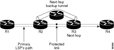
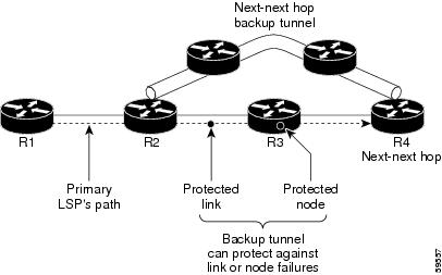


 Feedback