Timing and Synchronization Configuration Guide for Cisco 8000 Series Routers, Cisco IOS XR Releases
Bias-Free Language
The documentation set for this product strives to use bias-free language. For the purposes of this documentation set, bias-free is defined as language that does not imply discrimination based on age, disability, gender, racial identity, ethnic identity, sexual orientation, socioeconomic status, and intersectionality. Exceptions may be present in the documentation due to language that is hardcoded in the user interfaces of the product software, language used based on RFP documentation, or language that is used by a referenced third-party product. Learn more about how Cisco is using Inclusive Language.
Frequency synchronization is the ability to distribute precision frequency around a network. In this context, timing refers
to precision frequency, not an accurate time of day. Precision frequency is required in next generation networks for applications
such as circuit emulation.
Table 1. Feature History Table
Feature name
Release Information
Feature Description
Frequency Synchronization
Release 7.3.1
Based on the ITU-T G.8262 recommendations, precision frequency is enabled on timing devices to deliver frequency synchronization
for bandwidth, frequency accuracy, holdover, and measure noise generation. This allows for correct network operations when
synchronous equipment is timed from either another synchronous equipment clock or a higher-quality clock.
Frequency Synchronization Timing Concepts
Source and Selection Points
Frequency Synchronization implementation involves Sources and Selection Points.
Source
A Source inputs frequency signals into a system or transmits them out of a system. There are four types of sources:
Line interfaces: This includes SyncE interfaces.
Clock interfaces: These are external connectors for connecting other timing signals, such as BITS and GPS.
PTP clock: If IEEE 1588 version 2 is configured on the router, a PTP clock may be available to frequency synchronization as a source
of the time-of-day and frequency.
Internal oscillator: This is a free-running internal oscillator chip.
Each source has a Quality Level (QL) associated with it which gives the accuracy of the clock. This provides information about
the best available source the devices in the system can synchronize to. To define a predefined network synchronization flow
and prevent timing loops, you can assign priority values to the sources on each router. The combination of QL information
and user-assigned priority levels allow each router to choose a source to synchronize its SyncE interfaces, as described in
the ITU standard G.781.
Selection Point
A Selection Point is any point where a choice is made between several frequency signals and possibly one or many of them are
selected. Selection points form a graph representing the flow of timing signals between different cards in a router running
Cisco IOS XR software. For example, there can be one or many selection points between different Synchronous Ethernet inputs
available on a single-line card. This information is forwarded to a selection point on the router, to choose between the selected
source from each card.
The input signals to the selection points can be:
Received directly from a source.
Received as the output from another selection point on the same card
Received as the output from a selection point on a different card
The output of a selection point can be used in several ways, like:
To drive the signals sent out of a set of interfaces.
As input into another selection point on a card
As input into a selection point on another card
Use the show frequency synchronization selection command to see a detailed view of the different selection points within the system.
Synchronous Ethernet (SyncE)
SyncE is an ITU-T standard for computer networking that facilitates the transfer of clock signals over the Ethernet physical
layer. It uses the physical layer (Ethernet interfaces) to distribute frequency from the primary reference clock (PRC) to
downstream devices. It supports frequency transfer from hop to hop and is used to provide frequency synchronization in networks.
SDH equipment are widely replaced by Ethernet equipment and synchronized frequency is required over such Ethernet ports. SyncE
is used to accurately synchronize frequency in devices connected by Ethernet in a network. SyncE provides a level frequency
distribution of known common precision frequency references to a physical layer Ethernet network.
To maintain SyncE links, a set of operational messages are required. These messages ensure that a node is always deriving
timing information from the most reliable source and then transfers the timing source quality information to clock the SyncE
link. In SDH networks, these are known as Synchronization Status Messages (SSMs). SyncE uses an Ethernet Synchronization Message
Channel (ESMC) to provide transport for SSMs.
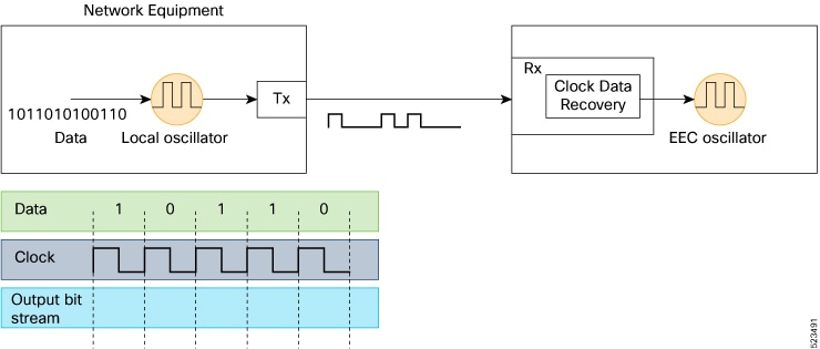
How SyncE Works?
SyncE operates on the fundamental principle of extracting clock frequency from the data received on a port.
Here’s an example. The local oscillator processes the data signal and the Tx port transmits the resulting output. You can
observe that the clock frequency is present in the data signal transmitted on the port. SyncE functions by reverse-processing
the signal received on the Rx port and obtains the frequency information of the transmitted clock.
Figure 1. Clock Frequency Extraction for SyncE
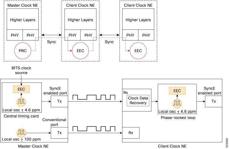
Per recommendation, the frequency from the bitstream is recovered in the physical layer. A clock known as the primary reference
clock (PRC), is distributed in the chain and all the network clocks must be traceable back to this PRC. To ensure traceable
clocks, all nodes within the chain connecting the Main Clock and the end device must actively adopt a synchronous Ethernet
Equipment Clock (EEC), in accordance with SyncE recommendations. The performance of the recovered clock remains unaffected
by network load as it doesn’t synchronize with specific packets.
Figure 2. Clock Deployment for SyncE
The Master Clock NE receives external timing references from the network clock (SSU or BITS), which are then used as inputs
to the EEC clock, typically located on the central timing card of the NE. The output timing reference from the EEC is used
to sample data and transmit traffic on the SyncE-enabled Tx port.
At the Client Clock NE, the clock is recovered within the transceiver clock data recovery (CDR). In some cases where the RX
clock isn’t available at the transceiver, the use of an external CDR might be required to recover the clock. The clock is
then sent through the backplane to reach the Client Clock’s central timing card. This timing reference then becomes a reference
to the EEC (also known as a line-timing reference). As shown in the Client Clock NE, an EEC can accept line and external references,
as well as the input of a ±4.6 ppm local oscillator (used in situations where there are no line or external references available).
From this point on, the Client Clock NE then becomes the Master Clock NE for the next downstream NE, and synchronization is
transported on a node-to-node basis, where each node participates in recovery and distribution.
In the case of the Client Clock NE, the clock recovery occurs within the transceiver's clock data recovery (CDR). In situations
where the RX clock is unavailable at the transceiver, the use of an external CDR may be necessary for clock recovery. The
recovered clock is then transmitted through the backplane to reach the Client Clock’s central timing card, which then becomes
a reference for the EEC (also known as a line-timing reference). As depicted in the Client Clock NE, an EEC can accept line
and external references, and the input of a ±4.6 ppm local oscillator (used when no line or external references are available).
From this point onward, the Client Clock NE becomes the Master Clock NE for the subsequent downstream NE, and synchronization
is conveyed on a node-to-node basis, with each node participating in recovery and distribution.
SyncE Profiles Support Matrix
This table provides information on the SyncE profiles that are supported on the Cisco 8000 series routers and line cards.
Table 2. SyncE Profiles Support Matrix
Hardware Module
Supported SyncE profiles
Cisco IOS XR Release
8711-32FH-M router
G.8262
G.8262.1
Release 24.3.1
8000-RP2 Route Processor
G8275.1
G8273.2
Release 7.11.1
88-LC0-36FH-M
G8275.1
G8273.2
Release 7.11.1
8800-LC-36FH
G8275.1
G8273.2
Release 7.11.1
88-LC0-36FH-M line card
8202-32FH-M router
G.8262
Release 7.5.2
G.8264
8201-32FH router
88-LC-34H14FH line card
88-LC0-36FH line card
G.8262
Release 7.3.3
G.8264
8201 router
8202 router
8800-LC-36FH line card
8800-LC-48FH line card
G.8262
Release 7.3.1
G.8264
SyncE Restrictions
SyncE isn’t supported on 8800-RP 1588 ports.
We recommend that you configure and enable Frequency Synchronization selection input on two interfaces per line card.
For link aggregation, configure and enable Frequency Synchronization selection input on a single bundle member.
Enhanced ESMC and Enhanced SyncE
The Ethernet Synchronization Message Channel (ESMC) protocol is specified in the ITU-T G.8264. It enables frequency synchronization
across a network over Ethernet ports with the ability to select enhanced quality levels. Enhanced quality levels lead to improved
bandwidth, frequency accuracy, and holdover along with reduced noise generation in a network.
As part of the ESMC protocol, Synchronization Status Messages (SSMs) distributes the Quality Level (QL) of timing signals.
The updated G.8264 standard provides a new and enhanced Quality Level (QL) of Type Length Value (TLV) that allows more precise
quality to provide accurate clocks.
The new and enhanced QL of TLV that is part of the updated G.8264 standard is known as enhanced SyncE (eSyncE). The enhanced QL of TLV enables support for more QL values. You can configure a router to send or receive the enhanced TLV.
The enhanced QL of TLV results in more precise synchronization of clocks across a network. To enable this feature, the local
clock ID is configured. The clock ID is used, when appropriate, in the extended QL TLVs.
Table 3. Feature History Table
Feature name
Release Information
Feature Description
Ethernet Synchronization Message Channel (ESMC)
Release 7.3.1
The ITU-T G.8264 performance compliance standard specifies the ESMC protocol, offering recommendations on synchronizing clock
frequency across a network via an Ethernet port and enabling the selection of quality levels. Within the G.8264 standard,
a new extended Quality Level (QL) in the form of Type Length Value (TLV) is provided. As networks progressively adopt Ethernet
equipment instead of SONET and SDH equipment, frequency synchronization actively delivers high-quality clock synchronization
over Ethernet ports.
Note
The default clock ID is based on the MAC address of the chassis.
ESMC Restrictions
There may be devices in a network that do not support eSyncE and also do not support enhanced ESMC. If a router does not support
eSyncE, it ignores any enhanced TLVs it receives and does not support enhanced quality to provide accurate clocks. Such routers
at ingress nodes drop the QL TLV received from the previous node supporting eSyncE. If the next node supports enhanced ESMC,
then the extended QL TLV is applied afresh to that node.
Configure Frequency Synchronization
This section details the various ways for configuring frequency synchronization. First frequency synchronization needs to
be enabled on the router which is detailed in Enable Frequency Synchronization on the Router section.
If SyncE is selected as the source for frequency synchronization, the configuration steps are detailed in the section Configure Frequency Synchronization on an Interface.For frequency synchronization using external clock interfaces (GPS or BITS), the configuration steps involved are detailed
in the sections Configure GPS, an external Clock Interface for Frequency Synchronization and Configure BITS, an external Clock Interface for Frequency Synchronization.
Frequency synchronization using PTP is detailed in the section G.8265.1 of the Precision Time Protocol (PTP) module of this document.
Enable Frequency Synchronization on the Router
This task describes the router-level configuration required to enable frequency synchronization.
Procedure
Step 1
Configure the type of timing sources that can be used to drive the output from a clock interface.
Router# config
Router(config)# frequency synchronization
Router(config-freqsync)# clock-interface timing-mode system
Note
If the timing mode system isn’t configured, the major alarm T4 PLL is in FREERUN mode is raised. This alarm has no functional impact to the system behavior.
Step 2
(Optional) Configure the ITU-T quality level (QL) options.
The quality option configured here must match the quality option specified in the quality receive and quality transmit commands in interface frequency synchronization configuration mode.
Configure frequency synchronization on any interfaces that should participate in frequency synchronization.
Configure Frequency Synchronization on an Interface
Configure SyncE
By default, there’s no frequency synchronization on line interfaces. Use this task to configure an interface to participate
in frequency synchronization.
Before you begin
You must enable frequency synchronization globally on the router.
Procedure
Step 1
Enter the interface frequency synchronization mode using frequency synchronization and interface commands.
Router# config
Router(config)# interface HundredGigE 0/1/1/0
Router(config-if)# frequency synchronization
Router(config-if-freqsync)#
Step 2
(Optional) Define the parameters for frequency synchronization.
The quality option specified in this command must match the globally configured quality option in the quality itu-t option command.
Note
For clock interfaces that don’t support SSM, only the lowest QL can be specified. In this case, rather than sending DNU, the
output is squelched, and no signal is sent.
Step 3
(Optional) Configure the SSM quality levels for the frequency source from the receive interface.
Configure the quality level options to be transmitted by the device clock.
Router(config)# interface HundredGigE 0/1/0/0
Router(config-if)# frequency synchronization
Router(config-if-freqsync)# quality transmit exact itu-t option 1 ePRTC
Router(config-if-freqsync)# end
Step 3
Verify eSyncE configuration.
Router# show frequency synchronization interfaces
Interface HundredGigE 0/11/0/1 (up)
  Assigned as input for selection
  Wait-to-restore time 0 minutes
  SSM Enabled
    Peer Up for 00:00:54, last SSM received 0.741s ago
    Peer has come up 1 times and timed out 0 times
    ESMC SSMs        Total  Information     Event    DNU/DUS
      Sent:             55           53         2         45
      Received:         55           55         0          0
  Input:
    Up
    Last received QL: Opt-I/ePRTC
    Effective QL: Opt-I/ePRTC, Priority: 30, Time-of-day Priority 100
    Originator clock ID: aaaabbfffebbcccc
    SyncE steps: 1, eSyncE steps: 1
    All steps run eSyncE; Chain of extended ESMC data is complete
    Supports frequency
  Output:
    Selected source: HundredGigE 0/11/0/1
    Selected source QL: Opt-I/ePRTC
    Effective QL: DNU
    Originator clock ID: aaaabbfffebbcccc
    SyncE steps: 2, eSyncE steps: 2
    All steps run eSyncE; Chain of extended ESMC data is complete
  Next selection points: ETH_RXMUX
Configure GPS, an external Clock Interface for Frequency Synchronization
Setting GPS
The router can receive 1PPS, 10 MHz, and ToD signals from an external clocking and timing source. The three inputs are combined
as a Sync-2 interface to form the external timing source or the GPS input.
The GPS front panel connector details are:
ToD—RS422 format as input
1PPS—RS422 or DIN connector as input
10MHz—DIN connector as input
GPS input starts only when all the three signals – 1PPS, 10MHz, and ToD are UP.
Note
Unlike the Ethernet interface, the Sync-2 interface can’t receive or transmit QL. Ensure that you assign a QL value to the
Sync-2 interface.
By default, 1PPS and 10MHz are in output mode. ToD output mode isn’t configurable.
For the variant, 8800-RP, 10MHZ and 1PPS can operate in output mode only when PTP Slave or BC mode are configured.
When the front panel timing LED is Green, it indicates that the GPS is configured and 1PPS, ToD, and 10M inputs are valid.
Timing GPS LED Behavior:
Timing GPS LED is off: Indicates that no GPS is configured or the GPS port is down.
Timing GPS LED is green: Indicates that the GPS port is up.
SYNC LED Behavior:
SYNC LED is green: Indicates that the time core is synchronized to either external source, or SyncE or 1588.
SYNC LED is amber: Indicates a Holdover or Acquiring state.
SYNC LED is off: Indicates synchronization in a disable or free-running state.
The following table describes the implication of LED light status of GPS, BITS port, and SYNC LEDs.
Table 4. LED Light States
LED Type
LED State
Description
GPS
Green
The GPS interface is provisioned and frequency, time of day, and phase input is operating accurately.
Off
The GPS interface isn’t provisioned or the GPS input isn’t operating accurately.
BITS port
Green
The BITS interface is provisioned and the frequency is operating accurately.
Off
The BITS interface isn’t provisioned or the BITS input isn’t operating accurately.
SYNC
Green
The frequency, time, and phase are synchronized to an external interface. The external interface can be:
BITS
GPS
Recovered RX clock.
Amber
The system is running in holdover or free-run mode and based on user configuration it’s not synchronized to an external interface,
as expected.
Off
The centralized frequency or time and phase distribution isn’t enabled. Therefore, all clocking is based on the local oscillator
on the RSP.
Configuring GPS Settings for the Grandmaster Clock
Procedure
Step 1
Configure the clock interface to synchronize with a GPS.
Configure the type of timing sources that can be used to drive the output from a clock interface.
Router(config-clock-if)# frequency synchronization
Router(config-clk-freqsync)# quality itu-t option 1
Router(config-clk-freqsync)# clock-interface timing-mode system
Router(config-clk-freqsync)# end
Step 4
Verify the GPS input.
Router# show controllers timing controller clock

SYNCC Clock-Setting: -1 -1 6 -1
             Port 0    Port 1    Port 2    Port 3
Config :     No        No        Yes       No
Mode :       -         -         GPS       -
Submode1 :   -         -         CISCO     -
Submode2 :   -         -         UTC       -
Submode3 :   0         0         0         0
Shutdown :   0         0         0         0
Direction :  RX/TX     RX/TX     RX        RX/TX
Baud-Rate :  -         -         9600      -
QL Option :  O1        O1        -         -
RX_ssm(raw): -         -         -         -
TX_ssm :     -         -         -         -
If_state :   DOWN      DOWN      UP        DOWN  << Port 2 is UP when GPS input is valid.
Configure BITS, an external Clock Interface for Frequency Synchronization
Your router supports the reception (Rx) and transmission (Tx) of frequency through the Building Integrated Timing Supply (BITS)
interface. To enable the reception and transmission of BITS signals, you actively configure the clock-interface sync 0 on
the route processor (RP).
Configuring BITS
Procedure
Step 1
Prerequisite for BITS
Frequency synchronization must be configured with the required quality level option at the global level.
Both RP0 and RP1 should have identical configurations and should be connected to the same external reference for sync 0 and
sync 2 to meet phase transient response compliance standards during RP failover.
BITS-In and BITS-Out on the peer nodes must be configured with the same mode and format.
Based on the quality level chosen in the global configuration, E1/T1 modes can be changed as required. But in all the cases,
both TX and RX side modes and submodes must be the same.
For non-CRC-4/D4 modes, SSM isn’t present in BITS and the manual receive quality level must be configured.
Router# show running-config clock-interface sync 0 location 0/RP0/CPU0
Wed Aug 21 12:31:43.350 UTC
clock-interface sync 0 location 0/RP0/CPU0
 port-parameters
  bits-input e1 crc-4 sa4 ami
 !
 frequency synchronization
  selection input
  priority 1
  wait-to-restore 0
 !
!
Router# show controllers timing controller clock
Wed Aug 21 12:38:20.394 UTC

SYNCC Clock-Setting: 1 -1 -1 -1

          Port 0          Port 1          Port 2          Port 3
Config     : Yes            No             No             No
Mode       : E1             -              -              -
Submode1   : CRC-4          -              -              -
Submode2   : AMI            -              -              -
Submode3   : 0              0              0              0
Shutdown   : 0              0              0              0
Direction  : RX             RX/TX          RX/TX          RX/TX
Baud-Rate  : -              -              -              -
QL Option  : O1             O1             -              -
RX_ssm(raw): 99             -              -              -
TX_ssm     : -              -              -              -
If_state   : UP           DOWN           DOWN           DOWN
Step 4
Configure BITS-OUT.
Router# config
Router(config)# clock-interface sync 0 location 0/RP0/CPU0
Router(config-clock-if)# port-parameters
Router(config-clk-parms)# bits-output e1 crc-4 sa4 ami
Router(config-clk-parms)# end
Step 5
Verify the BITS-OUT configuration.
Router# show running-config clock-interface sync 0 location 0/RP0/CPU0
Wed Aug 21 12:54:02.853 UTC
clock-interface sync 0 location 0/RP0/CPU0
 port-parameters
  bits-output e1 crc-4 sa4 ami
 !
!
Router# show controllers timing controller clock
Wed Aug 21 12:49:32.923 UTC
SYNCC Clock-Setting: 1 -1 -1 -1

          Port 0          Port 1          Port 2          Port 3
Config     : Yes            No             No             No
Mode       : E1             -              -              -
Submode1   : CRC-4          -              -              -
Submode2   : AMI            -              -              -
Submode3   : 0              0              0              0
Shutdown   : 0              0              0              0
Direction  : TX             RX/TX          RX/TX          RX/TX
Baud-Rate  : -              -              -              -
QL Option  : O1             O1             -              -
RX_ssm(raw): -              -              -              -
TX_ssm     : 22             -              -              -
If_state   : UP             DOWN           DOWN           DOWN
Step 6
Verify quality level received and clock interfaces.
Router# show frequency synchronization clock-interfaces brief
Tue Feb 23 23:42:22.654 UTC
Flags: > - Up               D - Down                          S - Assigned for selection
d - SSM Disabled            s - Output squelched              L - Looped back
Node 0/RP0/CPU0:
==============
Fl      Clock Interface       QLrcv    QLuse    Pri   QLsnd    Output driven by
=====   ===================   ======   ======   ===   ======   ========================
D       Sync0                 n/a      n/a      n/a   n/a      n/a
D       Sync1                 n/a      n/a      n/a   n/a      n/a
>S      Sync2                 None     PRC      100   n/a      n/a
>S      Internal0             n/a      SEC      255   n/a      n/a
Node 0/RP1/CPU0:
==============
Fl      Clock Interface       QLrcv    QLuse    Pri   QLsnd     Output driven by
=====   ===================   ======   ======   ===   ======    ========================
D       Sync0                 n/a      n/a      n/a   n/a       n/a
D       Sync1                 n/a      n/a      n/a   n/a       n/a
D       Sync2                 n/a      n/a      n/a   n/a       n/a
>S      Internal0             n/a      SEC      255   n/a       n/a
Verify the Frequency Synchronization Configuration
After performing the frequency synchronization configuration tasks, use this task to check for configuration errors and verify
the configuration.
Procedure
Step 1
Display any configuration errors related to frequency synchronization using show frequency synchronization configuration-errors command.
Router# show frequency synchronization configuration-errors

Node 0/2/CPU0:
==============
  interface HundredGigE 0/2/0/0 frequency synchronization
    * Frequency synchronization is enabled on this interface, but isn't enabled globally.

  interface HundredGigE 0/2/0/0 frequency synchronization quality transmit exact itu-t option 2 generation 1 PRS
    * The QL that is configured is from a different QL option set than is configured globally.
Displays any errors that are caused by inconsistencies between shared-plane (global) and local-plane (interface) configurations.
There are two possible errors that can be displayed:
The QL option configured on some interfaces does not match the global QL option. Under an interface (line interface or clock
interface), the QL option is specified using the quality transmit and quality receive commands. The value specified must match the value configured in the global quality itu-t option command, or match the default (option 1) if the global quality itu-t option command is not configured.
Once all the errors have been resolved, meaning there is no output from the command, continue to the next step.
Step 2
Verify the configuration using show frequency synchronization interfaces brief and show frequency synchronization clock-interfaces brief commands.
Router# show frequency synchronization interfaces brief

Flags:  > - Up                D - Down              S - Assigned for selection
        d - SSM Disabled      x - Peer timed out    i - Init state

Fl  Interface                QLrcv QLuse Pri QLsnt Source
=== ======================== ===== ===== === ===== ========================
>Sx HundredGigE 0/2/0/0   Fail  Fail  100 DNU   None
Dd  HundredGigE 0/2/0/1   n/a   Fail  100 n/a   None

Router# show frequency synchronization clock-interfaces brief

Flags:  > - Up                D - Down              S - Assigned for selection
        d - SSM Disabled      s - Output squelched  L - Looped back

Node 0/0/CPU0:
==============
  Fl    Clock Interface     QLrcv  QLuse  Pri QLsnd  Source
  ===== =================== ====== ====== === ====== ========================
  >S    Sync0               PRC    Fail   100 SSU-B  Internal0 [0/0/CPU0]

  >S    Internal0           n/a    SSU-B  255 n/a    None

Node 0/1/CPU0:
==============
  Fl    Clock Interface     QLrcv  QLuse  Pri QLsnd  Source
  ===== =================== ====== ====== === ====== ========================
  D     Sync0               None   Fail   100 SSU-B  Internal0 [0/1/CPU0]

  >S    Internal0           n/a    SSU-B  255 n/a    None
Note the following points:
All line interfaces that have frequency synchronization configured are displayed.
All clock interfaces and internal oscillators are displayed.
Sources that have been nominated as inputs (in other words, have selection input configured) have ‘S’ in the Flags column; sources that have not been nominated as inputs do not have ‘S’ displayed.
Note
Internal oscillators are always eligible as inputs.
‘>’ or ‘D’ is displayed in the flags field as appropriate.
If any of these items are not true, continue to the next step.
Step 3
Investigate issues within individual interfaces using show frequency synchronization interfaces and show frequency synchronization clock-interfaces commands.
Router# show frequency synchronization interfaces HundredGigE 0/2/0/2

Interface HundredGigE 0/2/0/2 (shutdown)
  Assigned as input for selection
  SSM Enabled
  Input:
    Down
    Last received QL: Failed
    Effective QL:     Failed, Priority: 100
  Output:
    Selected source:    Sync0 [0/0/CPU0]
    Selected source QL: Opt-I/PRC
    Effective QL:       Opt-I/PRC
  Next selection points: LC_INGRESS

Router# show frequency synchronization clock-interfaces location 0/1/CPU0

Node 0/1/CPU0:
==============
  Clock interface Sync0 (Down: mode not configured)
    SSM supported and enabled
    Input:
      Down
      Last received QL: Opt-I/PRC
      Effective QL:     Failed, Priority: 100
    Output:
      Selected source:    Internal0 [0/1/CPU0]
      Selected source QL: Opt-I/SSU-B
      Effective QL:       Opt-I/SSU-B
  Next selection points: RP_SYSTEM


  Clock interface Internal0 (Up)
    Assigned as input for selection
    Input:
      Default QL:   Opt-I/SSU-B
      Effective QL: Opt-I/SSU-B, Priority: 255
  Next selection points: RP_SYSTEM RP_CLOCK_INTF
If the clock interface is down, a reason is displayed. This may be because there is missing or conflicting platform configuration
on the clock interface.
Step 4
Verify that the fsyncmgr process is running on the appropriate nodes using show processes fsyncmgr location command.
Router# show processes fsyncmgr location 0/0/CPU0

                  Job Id: 134
                     PID: 30202
         Executable path: /pkg/bin/fsyncmgr
              Instance #: 1
              Version ID: 00.00.0000
                 Respawn: ON
           Respawn count: 1
  Max. spawns per minute: 12
            Last started: Mon Mar  9 16:30:43 2009
           Process state: Run
           Package state: Normal
       Started on config: cfg/gl/freqsync/g/a/enable
                    core: MAINMEM
               Max. core: 0
               Placement: None
            startup_path: /pkg/startup/fsyncmgr.startup
                   Ready: 0.133s
        Process cpu time: 1730768.741 user, -133848.-361 kernel, 1596920.380 total
  --------------------------------------------------------------------------------

 Feedback