Managing Router Hardware

This chapter describes the concepts and tasks used to manage and configure the hardware components of a router running the Cisco IOS XR software.

This module contains the following topics:

RP Redundancy and Switchover

This section describes RP redundancy and switchover commands and issues.

Establishing RP Redundancy

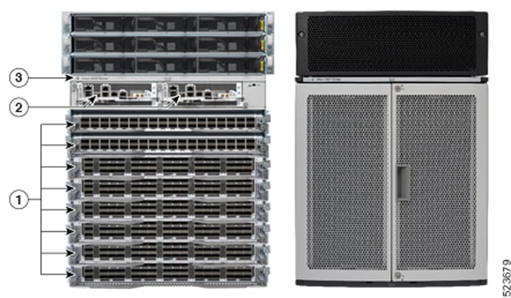
Your router has two slots for RPs: RP0 and RP1 (see Redundant Set of RP Installed in Slots RP0 and RP1 in an Cisco 8608 8-Slot Centralized Chassis and Redundant Set of RP Installed in Slots RP0 and RP1 in an Cisco 8808 8-Slot Distributed Chassis). RP0 is the slot on the left, facing the front of the chassis, and RP1 is the slot on right. These slots are configured for redundancy by default, and the redundancy cannot be eliminated. To establish RP redundancy, install RP into both slots.

Figure 1. Redundant Set of RP Installed in Slots RP0 and RP1 in an Cisco 8608 8-Slot Centralized Chassis
Figure 2. Redundant Set of RP Installed in Slots RP0 and RP1 in an Cisco 8808 8-Slot Distributed Chassis

1

Modular Port Adaptors (MPAs)

2

Route Processors (RPs)

3

Chassis

Determining the Active RP in a Redundant Pair

During system startup, one RP in each redundant pair becomes the active RP. You can tell which RP is the active RP in the following ways:

  • The active RP can be identified by the green Active LED on the faceplate of the card. When the Active LED turns on, it indicates that the RP is active and when it turns off, it indicates that the RP is in standby.

  • The slot of the active RP is indicated in the CLI prompt. For example:

    
    RP/0/RP1/CPU0:router#
      

    In this example, the prompt indicates that you are communicating with the active RP in slot RP1.

  • Enter the show redundancy command in EXEC mode to display a summary of the active and standby RP status. For example:

    
    RP/0/RP0/CPU0:router# show redundancy
      
      This node (0/RP0/CPU0) is in ACTIVE role
      Partner node (0/RP1/CPU0) is in STANDBY role
      Standby node in 0/RP1/CPU0 is ready
      
      Reload and boot info
      ----------------------
      RP reloaded Fri Apr  9 03:44:28 2004: 16 hours, 51 minutes ago
      This node booted Fri Apr  9 06:19:05 2004: 14 hours, 16 minutes ago
      Last switch-over Fri Apr  9 06:53:18 2004: 13 hours, 42 minutes ago
      Standby node boot Fri Apr  9 06:54:25 2004: 13 hours, 41 minutes ago
      Standby node last not ready Fri Apr  9 20:35:23 2004: 0 minutes ago
      Standby node last ready Fri Apr  9 20:35:23 2004: 0 minutes ago
      There have been 2 switch-overs since reload

Role of the Standby RP

The second RP to boot in a redundant pair automatically becomes the standby RP. While the active RP manages the system and communicates with the user interface, the standby RP maintains a complete backup of the software and configurations for all cards in the system. If the active RP fails or goes off line for any reason, the standby RP immediately takes control of the system.

Summary of Redundancy Commands

RP redundancy is enabled by default in the Cisco IOS XR software, but you can use the commands described in Table 1 to display the redundancy status of the cards or force a manual switchover.

Table 1. RP Redundancy Commands

Command

Description

show redundancy

Displays the redundancy status of the RP. This command also displays the boot and switch-over history for the RP.

redundancy switchover

Forces a manual switchover to the standby RP. This command works only if the standby RP is installed and in the “ready” state.

show platform

Displays the status for node, including the redundancy status of the RP cards. In EXEC mode, this command displays status for the nodes assigned to the SDR. In administration EXEC mode, this command displays status for all nodes in the system.

Automatic Switchover

Automatic switchover from the active RP to the standby RP occurs only if the active RP encounters a serious system error, such as the loss of a mandatory process or a hardware failure. When an automatic switchover occurs, the RPs respond as follows:

  • If a standby RP is installed and “ready” for switchover, the standby RP becomes the active RP. The original active RP attempts to reboot.

  • If the standby RP is not in “ready” state, then both RPs reboot. The first RP to boot successfully assumes the role of active RP.

RP Redundancy During RP Reload

The reload command causes the active RP to reload the Cisco IOS XR software. When an RP reload occurs, the RPs respond as follows:

  • If a standby RP is installed and “ready” for switchover, the standby RP becomes the active RP. The original active RP reboots and becomes the standby RP.

  • If the standby RP is not in the “ready” state, then both RPs reboot. The first RP to boot successfully assumes the role of active RP.

Manual Switchover

If a standby RP is installed and ready for switchover, you can force a manual switchover using the redundancy switchover command or reloading the active RP using the reload command.

Manual Switchover Using the Reload Command

You can force a manual switchover from the active RP to the standby RP by reloading the active RP using the reload command. As active RP reboots, the current standby RP becomes active RP, and rebooting RP switches to standby RP.

RP/0/RP0/CPU0:router# reload
RP/0/RP1/CPU0:router#

Manual Switchover Using the Redundancy Switchover Command

You can force a manual switchover from the active RP to the standby RP using the redundancy switchover command.

If a standby RP is installed and ready for switchover, the standby RP becomes the active RP. The original active RP becomes the standby RP. In the following example, partial output for a successful redundancy switchover operation is shown:


RP/0/RP0/CPU0:router# show redundancy
  
  This node (0/RP0/CPU0) is in ACTIVE role
  Partner node (0/RP1/CPU0) is in STANDBY role
  Standby node in 0/RP1/CPU0 is ready
  
  RP/0/RP0/CPU0:router# redundancy switchover
  Updating Commit Database.  Please wait...[OK]
  Proceed with switchover 0/RP0/CPU0 -> 0/RP1/CPU0? [confirm]
  Initiating switch-over.
  RP/0/RP0/CPU0:router#
  
  <Your 'TELNET' connection has terminated>
  

In the preceding example, the Telnet connection is lost when the previously active RP resets. To continue management of the router, you must connect to the newly activated RP as shown in the following example:


User Access Verification
  
  Username: xxxxx
  Password: xxxxx
  Last switch-over Sat Apr 15 12:26:47 2009: 1 minute ago
  
RP/0/RP1/CPU0:router#
  

If the standby RP is not in “ready” state, the switchover operation is not allowed. In the following example, partial output for a failed redundancy switchover attempt is shown:


RP/0/RP0/CPU0:router# show redundancy 
  
  Redundancy information for node 0/RP1/CPU0:
  ==========================================
  Node 0/RP0/CPU0 is in ACTIVE role
  Partner node (0/RP1/CPU0) is in UNKNOWN role
  
  Reload and boot info
  ----------------------
  RP reloaded Wed Mar 29 17:22:08 2009: 2 weeks, 2 days, 19 hours, 14 minutes ago
  Active node booted Sat Apr 15 12:27:58 2009: 8 minutes ago
  Last switch-over Sat Apr 15 12:35:42 2009: 1 minute ago
  There have been 4 switch-overs since reload
  
  RP/0/RP0/CPU0:router# redundancy switchover
  
  Switchover disallowed: Standby node is not ready.
  

Communicating with a Standby RP

The active RP automatically synchronizes all system software, settings, and configurations with the standby RP.

If you connect to the standby RP through the console port, you can view the status messages for the standby RP. The standby RP does not display a CLI prompt, so you cannot manage the standby card while it is in standby mode.

If you connect to the standby RP through the management Ethernet port, the prompt that appears is for the active RP, and you can manage the router the same as if you had connected through the management Ethernet port on the active RP.

NPU Power Optimization

Table 2. Feature History Table

Feature Name

Release Information

Description

NPU Power Optimization

Release 7.3.15

This feature lets you choose a predefined NPU power mode based on your network's individual requirements, and consequently reducing NPU power consumption.

The hw-module npu-power-profile command is introduced for this feature.

Cisco 8000 series routers are powered by Cisco Silicon One Q200 and Q100 series processors. Cisco Silicon One processors offer high performance, flexible, and power-efficient routing silicon in the market.

NPU Power Optimization feature helps to reduce NPU power consumption by running a processor in a predefined mode. There are three NPU power modes—high, medium, and low. Based on your network traffic and power consumption requirements, you can choose to run the processor in any one of the three NPU power modes.

  • High: The router will use the maximum amount of power, resulting in the best possible performance.

  • Medium: The router power consumption and performance levels are both average.

  • Low: The router operates with optimal energy efficiency while providing a modest level of performance.


Note


We recommend that you work with your Cisco account representatives before implementing this feature in your network.


On a Q200-based Cisco 8200 series chassis, you can configure an NPU power mode on the entire router.

On a Q200-based Cisco 8800 series chassis, you can configure an NPU power mode only on fabric cards and line cards.

The following table lists the supported hardware, and their default NPU power mode:

Table 3. Supported Hardware and Default Modes

Supported Hardware

Default NPU Power Mode

Cisco 8200 32x400 GE 1RU fixed chassis (8201-32FH)

High

88-LC0-36FH without MACSec, based on Q200 Silicon Chip

Medium

88-LC0-36FH-M with MACSec, based on Q200 Silicon Chip

Medium

8808-FC0 Fabric Card, based on Q200 Silicon Chip

Low

8818-FC0 Fabric Card, based on Q200 Silicon Chip

Medium


Caution


We recommend that you use the default NPU power mode on your router.


Limitations

The NPU power optimization is not supported on the Q100-based systems.

The NPU Power Profile mode is not supported on the following Q200-based line cards:

Table 4. Limitation on Hardware and Power Profile Modes

Hardware

Power Profile Mode

88-LC0-36FH-M

High

88-LC0-34H14FH

High

Configuring NPU Power Mode

Configuring NPU power mode on a fixed chassis:

The following example shows how to configure an NPU power mode on a fixed chassis:


RP/0/RP0/CPU0:ios(config)#hw-module npu-power-profile high
RP/0/RP0/CPU0:ios(config)#commit

RP/0/RP0/CPU0:ios(config)#reload

Note


Note: Reload the chassis for the configurations changes to take effect.


Verifying NPU power mode configuration on a fixed chassis:

Use the show controllers npu driver command to verify the NPU power mode configuration:

RP/0/RP0/CPU0:ios#show controllers npu driver location 0/RP0/CPU0
Mon Aug 24 23:29:34.302 UTC
==============================================
NPU Driver Information
==============================================
Driver Version: 1
SDK Version: 1.32.0.1  
Functional role: Active,     Rack: 8203, Type: lcc, Node: 0
Driver ready      : Yes
NPU first started : Mon Aug 24 23:07:41 2020
Fabric Mode:
NPU Power profile: High
Driver Scope: Node
Respawn count     : 1
Availablity masks :
        card: 0x1,     asic: 0x1,    exp asic: 0x1
...

Configuring NPU power mode on a modular chassis

The following example shows how to configure an NPU power mode on a fabric card and a line card:


RP/0/RP0/CPU0:ios(config)#hw-module npu-power-profile card-type FC high
RP/0/RP0/CPU0:ios(config)#hw-module npu-power-profile card-type LC low location 0/1/cpu0
RP/0/RP0/CPU0:ios(config)#commit

Note


For the configurations to take effect, you must:

  • Reload a line card if the configuration is applied on the line card.

  • Reload a router if the configuration is applied on a fabric card.


Verifying the NPU power mode configuration on a modular chassis

Use the show controllers npu driver location command to verify the NPU power mode configuration:

RP/0/RP0/CPU0:ios#show controllers npu driver location 0/1/CPU0
 
Functional role: Active,     Rack: 8808, Type: lcc, Node: 0/RP0/CPU0
Driver ready      : Yes
NPU first started : Mon Apr 12 09:57:27 2021
Fabric Mode: FABRIC/8FC
NPU Power profile: High
Driver Scope: Rack
Respawn count     : 1
Availablity masks :
        card: 0xba,     asic: 0xcfcc,    exp asic: 0xcfcc
Weight distribution:
        Unicast: 80,      Multicast: 20
+----------------------------------------------------------------+
| Process | Connection | Registration | Connection | DLL         |
| /Lib    | status     | status       | requests   | registration|
+----------------------------------------------------------------+
| FSDB    | Active     | Active       |           1|  n/a        |
| FGID    | Active     | Active       |           1|  n/a        |
| AEL     | n/a        | n/a          |         n/a|  Yes        |
| SM      | n/a        | n/a          |         n/a|  Yes        |
+----------------------------------------------------------------+
          
Asics :   
HP - HotPlug event, PON - Power On reset
HR - Hard Reset,    WB  - Warm Boot
+------------------------------------------------------------------------------+
| Asic inst. | fap|HP|Slice|Asic|Admin|Oper | Asic state | Last |PON|HR |  FW  |
|  (R/S/A)   | id |  |state|type|state|state|            | init |(#)|(#)|  Rev |
+------------------------------------------------------------------------------+
| 0/FC1/2    | 202| 1| UP  |s123| UP  | UP  |NRML        |PON   |  1|  0|0x0000|
| 0/FC1/3    | 203| 1| UP  |s123| UP  | UP  |NRML        |PON   |  1|  0|0x0000|
| 0/FC3/6    | 206| 1| UP  |s123| UP  | UP  |NRML        |PON   |  1|  0|0x0000|
| 0/FC3/7    | 207| 1| UP  |s123| UP  | UP  |NRML        |PON   |  1|  0|0x0000|
| 0/FC4/8    | 208| 1| UP  |s123| UP  | UP  |NRML        |PON   |  1|  0|0x0000|
| 0/FC4/9    | 209| 1| UP  |s123| UP  | UP  |NRML        |PON   |  1|  0|0x0000|
| 0/FC5/10   | 210| 1| UP  |s123| UP  | UP  |NRML        |PON   |  1|  0|0x0000|
| 0/FC5/11   | 211| 1| UP  |s123| UP  | UP  |NRML        |PON   |  1|  0|0x0000|
| 0/FC7/14   | 214| 1| UP  |s123| UP  | UP  |NRML        |PON   |  1|  0|0x0000|
| 0/FC7/15   | 215| 1| UP  |s123| UP  | UP  |NRML        |PON   |  1|  0|0x0000|
+------------------------------------------------------------------------------+
          
SI Info : 
+--------------------------------------------------------------------------------------------+
|   Card  | Board      | SI Board | SI Param | Retimer SI    | Retimer SI    | Front Panel   |
|         | HW Version | Version  | Version  | Board Version | Param Version | PHY           |
+--------------------------------------------------------------------------------------------+
|  FC1    |  0.22      |     1    |     6    |       NA      |       NA      |       NA      |
|  FC3    |  0.21      |     1    |     6    |       NA      |       NA      |       NA      |
|  FC4    |  0.21      |     1    |     6    |       NA      |       NA      |       NA      |
|  FC5    |  0.21      |     1    |     6    |       NA      |       NA      |       NA      |
|  FC7    |  0.21      |     1    |     6    |       NA      |       NA      |       NA      |
+--------------------------------------------------------------------------------------------+
Functional role: Active,     Rack: 8808, Type: lcc, Node: 0/1/CPU0
Driver ready      : Yes
NPU first started : Mon Apr 12 09:58:10 2021
Fabric Mode: FABRIC/8FC
NPU Power profile: Low
Driver Scope: Node
Respawn count     : 1
Availablity masks :
        card: 0x1,     asic: 0x7,    exp asic: 0x7
Weight distribution:
        Unicast: 80,      Multicast: 20
+----------------------------------------------------------------+
| Process | Connection | Registration | Connection | DLL         |
| /Lib    | status     | status       | requests   | registration|
+----------------------------------------------------------------+
| FSDB    | Active     | Active       |           1|  n/a        |
| FGID    | Inactive   | Inactive     |           0|  n/a        |
| AEL     | n/a        | n/a          |         n/a|  Yes        |
| SM      | n/a        | n/a          |         n/a|  Yes        |
+----------------------------------------------------------------+
          
Asics :   
HP - HotPlug event, PON - Power On reset
HR - Hard Reset,    WB  - Warm Boot
+------------------------------------------------------------------------------+
| Asic inst. | fap|HP|Slice|Asic|Admin|Oper | Asic state | Last |PON|HR |  FW  |
|  (R/S/A)   | id |  |state|type|state|state|            | init |(#)|(#)|  Rev |
+------------------------------------------------------------------------------+
| 0/2/0      |   8| 1| UP  |npu | UP  | UP  |NRML        |PON   |  1|  0|0x0000|
| 0/2/1      |   9| 1| UP  |npu | UP  | UP  |NRML        |PON   |  1|  0|0x0000|
| 0/2/2      |  10| 1| UP  |npu | UP  | UP  |NRML        |PON   |  1|  0|0x0000|
+------------------------------------------------------------------------------+
          
SI Info : 
+--------------------------------------------------------------------------------------------+
|   Card  | Board      | SI Board | SI Param | Retimer SI    | Retimer SI    | Front Panel   |
|         | HW Version | Version  | Version  | Board Version | Param Version | PHY           |
+--------------------------------------------------------------------------------------------+
|  LC2    |  0.41      |     1    |     9    |       NA      |       NA      |  DEFAULT      |
+--------------------------------------------------------------------------------------------+

Dynamic Power Management

Table 5. Feature History Table

Feature Name

Release Information

Description

Dynamic Power Management

Release 7.3.15

The Dynamic Power Management feature considers certain dynamic factors before allocating power to the fabric and line cards.

This feature has the following benefits:

  • Reduces number of PSUs required by accurately representing the maximum power consumption

  • Improves PSU efficiency by providing more accurate power allocation

This feature thus optimizes power allocation and avoids overprovisioning power to a router.

Dynamic Power Management

Release 7.3.2

Previously available for fabric and line cards, this feature that helps avoid excess power allocation by considering dynamic factors before allocating power to them is now available for optical modules.

To view the power allocation on a per port basis, a new command “show environment power allocated [details]" is introduced.

Dynamic Power Management

Release 7.3.3

The Dynamic Power Management feature is now supported on the following Cisco 8100 and 8200 series routers:

  • Cisco 8201

  • Cisco 8202

  • Cisco 8201-32-FH

  • Cisco 8101-32-FH

Dynamic Power Management

Release 7.5.2

The Cisco 8202-32FH-M router will now consider dynamic factors, such as optical modules, NPU power profile, and MACsec mode to enable improved power allocation and utilization.

Prior to Cisco IOS XR Release 7.3.15, when Cisco 8000 series routers were powered on or reloaded, the power management feature reserved power to fabric cards and allocated maximum power to line cards. The power management feature wouldn’t consider dynamic factors, such as the type of fabric or line cards in the chassis, or whether a fabric or line card was present in a slot.

The Dynamic Power Management feature considers such dynamic factors before allocating power to the fabric and line cards.

This feature has the following benefits:

  • Reduces number of PSUs required by accurately representing the maximum power consumption

  • Improves PSU efficiency by providing more accurate power allocation

This feature thus optimizes power allocation and avoids overprovisioning power to a router.

This feature is supported on the following Cisco 8000 series routers:

  • Cisco 8804, 8808, 8812, and 8818 routers

  • Cisco 8201, 8202, 8201-32-FH, and 8202-32FH-M routers

  • Cisco 8101-32-FH

By default, this feature is enabled on the router.

The Dynamic Power Management feature allocates the total power to a router and its fabric card or line card based on the following parameters:

  • Number and type of fabric cards installed on the router

  • Fabric cards operating modes (5FC or 8FC)

  • Number and type of line cards installed on the router

  • Combination of line card and fabric card types installed

  • NPU power mode configured on a fabric card

  • Number and type of optics installed (supported in Cisco IOS XR Software Release 7.3.2 and later)

  • MACSec-enabled ports (supported from Cisco IOS XR Software Release 7.3.3 and later)

    For details, see Dynamic Power Management for MACSec-Enabled Ports section in the Configuring MACSec chapter in the System Security Configuration Guide for Cisco 8000 Series Routers.

On 8202-32FH-M router, the Dynamic Power Management feature allocates the total power to a router based on the following parameters:

  • Optical modules installed.

  • NPU power profile. To identify the mode on which the router is operating, use the hw-module npu-power-profile command.

  • MACSec mode. By default, MACSec mode is disabled on 8202-32FH-M router.


Note


We recommend you work with your Cisco account representatives to calculate power requirements for the Cisco 8000 series router.

Power Allocation to Empty Card Slot

This feature allocates a minimum required power for all empty LC or FC slots. This minimum power is required to boot the CPU and FPGAs immediately when a card is inserted. The feature doesn't control booting up the CPU and FPGAs. Also, the minimum power is required to detect the card type before the feature decides if there’s enough power to power up the data path.

For example, the following show environment power command output displays various LC or FC card statuses, and also shows allocated and used power.


Note


The allocated power capacity shown in the following show command output isn’t standard capacity. The allocated power capacity varies depending on various other factors.


Router# show environment power 
Thu Apr 22 12:03:06.754 UTC
================================================================================
CHASSIS LEVEL POWER INFO: 0
================================================================================
   Total output power capacity (N + 1)             :    9600W +     6300W
   Total output power required                     :    9241W
   Total power input                               :    6146W
   Total power output                              :    5826W

================================================================================
   Power       Supply         -------Input--------   -----Output---     Status
   Module      Type            Volts A/B   Amps A/B   Volts     Amps     
================================================================================
   0/PT0-PM0   PSU6.3KW-HV     245.5/245.7 5.1/5.0    54.7      43.1     OK
   0/PT0-PM1   PSU6.3KW-HV     0.0/245.2   0.0/7.4    54.3      31.7     OK
   0/PT0-PM2   PSU6.3KW-HV     0.0/246.9   0.0/7.5    54.1      32.3     OK

Total of Power Modules:       6146W/25.0A              5826W/107.1A

================================================================================
   Location     Card Type               Power       Power        Status
                                        Allocated   Used
                                        Watts       Watts
================================================================================
   0/RP0/CPU0   8800-RP                 95          69           ON
   0/RP1/CPU0   -                       95          -            RESERVED
   0/0/CPU0     88-LC0-36FH             796         430          ON
   0/1/CPU0     -                       102         -            RESERVED
   0/2/CPU0     88-LC0-36FH             796         430          ON
   0/3/CPU0     -                       102         -            RESERVED
   0/4/CPU0     -                       102         -            RESERVED
   0/5/CPU0     -                       102         -            RESERVED
   0/6/CPU0     -                       102         -            RESERVED
   0/7/CPU0     -                       102         -            RESERVED
   0/8/CPU0     -                       102         -            RESERVED
   0/9/CPU0     88-LC0-36FH             102         -            OFF
   0/10/CPU0    -                       102         -            RESERVED
   0/11/CPU0    -                       102         -            RESERVED
   0/FC0        -                       26          -            RESERVED
   0/FC1        -                       26          -            RESERVED
   0/FC2        -                       26          -            RESERVED
   0/FC3        8812-FC                 784         509          ON
   0/FC4        8812-FC                 784         503          ON
   0/FC5        8812-FC                 26          -            OFF
   0/FC6        8812-FC                 26          -            OFF
   0/FC7        8812-FC                 26          -            OFF
   0/FT0        8812-FAN                1072        1000         ON
   0/FT1        8812-FAN                1072        1012         ON
   0/FT2        8812-FAN                1072        861          ON
   0/FT3        8812-FAN                1072        1033         ON

This table describes the card slot statuses:

Table 6. Router Card Slot Status

Status

Description

RESERVED

When a slot is empty

OFF

When a card is inserted in a slot but power isn’t allocated to the card

ON

When a card is allocated power and the card is in operational state

Low-Power Condition

When you insert an LC or FC in a card slot at the time when the router doesn't have enough power available to allocate to the new card, the dynamic power management feature doesn't provision power to the card. It raises the ev_power_budget_not_ok alarm, and gracefully shuts down the card.

In the following show command output, an FC inserted in the card slot location 0/FC6 is gracefully shut down due to lack of power:

Router# show shelfmgr history events location 0/FC6
Thu Apr 22 12:03:11.763 UTC
NODE NAME     : 0/FC6
CURRENT STATE : CARD_SHUT_POWERED_OFF
TIME STAMP    : Apr 20 2021 16:49:52
--------------------------------------------------------------------------------
DATE        TIME (UTC)  EVENT                    STATE
--------------------------------------------------------------------------------
Apr 20 2021 16:49:52    ev_powered_off           CARD_SHUT_POWERED_OFF
Apr 20 2021 16:49:52    ev_device_offline        STATE_NOT_CHANGED
Apr 20 2021 16:49:52    ev_unmapped_event        STATE_NOT_CHANGED
Apr 20 2021 16:49:48    transient_condition      CARD_SHUTDOWN
Apr 20 2021 16:49:48    ev_check_card_down_reaso CHECKING_DOWN_REASON
Apr 20 2021 16:49:48    ev_timer_expiry          CARD_SHUTDOWN_IN_PROGRESS
Apr 20 2021 16:48:46    ev_power_budget_not_ok   CARD_SHUTDOWN_IN_PROGRESS
Apr 20 2021 16:48:45    transient_condition      POWER_BUDGET_CHECK
Apr 20 2021 16:48:45    ev_fpd_upgrade_not_reqd  CARD_STATUS_CHECK_COMPLETE
Apr 20 2021 16:47:45    ev_card_status_check     CARD_STATUS_CHECK
Apr 20 2021 16:47:45    ev_card_info_rcvd        CARD_INFO_RCVD
Apr 20 2021 16:47:44    ev_device_online         DEVICE_ONLINE
Apr 20 2021 16:47:43    ev_timer_expiry          CARD_POWERED_ON
Apr 20 2021 16:47:33    ev_powered_on            CARD_POWERED_ON
Apr 20 2021 16:47:33    init                     CARD_DISCOVERED
--------------------------------------------------------------------------------

However, after an LC, FC, or chassis reload, the dynamic power management feature can't ensure that the same LCs, FCs, optics, or interfaces, which were operational earlier (before the reload), would become active again.


Note


During a low-power condition, this feature doesn’t borrow power from a redundant power supply.

Power Allocation to Optics

From Cisco IOS XR Release 7.3.2 onwards, power requirement for optics is also considered before allocating power to them.

To identify the power allocated for a particular interface, use the show environment power allocated [details] location location command.

When the optical modules are inserted, power is automatically allocated for that interface. If power has been allocated to the interface, then use the “no shut” command to enable the interface.

Router# show environment power allocated location 0/3/CPU0
Thu Oct  7 22:27:35.732 UTC
================================================================================
   Location    Components               Power
                                        Allocated
                                        Watts
================================================================================
  0/3/CPU0     Data-path                772          
               OPTICS                   138          
================================================================================
               Total                    910          

Router# show environment power allocated details location 0/3/CPU0 
Thu Oct  7 22:27:42.221 UTC
================================================================================
   Location    Components               Power
                                        Allocated
                                        Watts
================================================================================
  0/3/CPU0     Data-path                772          
               0/3/0/0                  3            
               0/3/0/1                  3            
               0/3/0/2                  3            
               0/3/0/3                  3            
               0/3/0/4                  3            
               0/3/0/5                  3            
               0/3/0/6                  3            
               0/3/0/7                  3            
               0/3/0/8                  3            
               0/3/0/9                  3            
               0/3/0/10                 3            
               0/3/0/11                 3            
               0/3/0/12                 3            
               0/3/0/13                 3            
               0/3/0/14                 3            
               0/3/0/15                 3            
               0/3/0/16                 3            
               0/3/0/17                 3            
               0/3/0/18                 3            
               0/3/0/19                 3            
               0/3/0/20                 3            
               0/3/0/21                 3            
               0/3/0/22                 3            
               0/3/0/23                 3            
               0/3/0/24                 3            
               0/3/0/25                 3            
               0/3/0/26                 3            
               0/3/0/27                 3            
               0/3/0/28                 3            
               0/3/0/29                 3            
               0/3/0/30                 3            
               0/3/0/31                 3            
               0/3/0/32                 3            
               0/3/0/33                 3            
               0/3/0/34                 3            
               0/3/0/35                 3            
               0/3/0/36                 3            
               0/3/0/37                 3            
               0/3/0/38                 3            
               0/3/0/39                 3            
               0/3/0/40                 3            
               0/3/0/41                 3            
               0/3/0/42                 3            
               0/3/0/43                 3            
               0/3/0/44                 3            
               0/3/0/46                 3            
================================================================================
               Total                    910          
When the power is not allocated to the interface, the following syslog error and alarms are displayed
!<--Syslog Error-->!
#LC/0/3/CPU0:Oct  7 22:46:48.114 UTC: optics_driver[165]: %PKT_INFRA-FM-3-FAULT_MAJOR : ALARM_MAJOR :POWER ALLOCATION FAIL :DECLARE :0/3/CPU0:  Optics0/3/0/44 
LC/0/3/CPU0:Oct  7 22:46:48.114 UTC: optics_driver[165]: %L2-OPTICS-2-QSFP_POWER_ALLOCATION_FAILURE : Not enough power available to enable Optics 0/3/0/44 

!<--Alarm-->!
Router#show alarms brief system active 
Thu Oct  7 22:47:19.569 UTC
 
------------------------------------------------------------------------------------
Active Alarms 
------------------------------------------------------------------------------------
Location        Severity     Group            Set Time                   Description                                                                                                                                                                                                                                                
------------------------------------------------------------------------------------
0/3/CPU0        Major        Software         10/07/2021 22:46:48 UTC     Optics0/3/0/44 - hw_optics:  Lack of available power to enable the optical module                                                                                                                                                                         
0/3/CPU0        Major        Software         10/07/2021 22:47:06 UTC     Optics0/3/0/46 - hw_optics:  Lack of available power to enable the optical module  
 

If power is not allocated to an interface and you attempt to enable that interface using the “no shut” command, the following syslog error is displayed:

LC/0/2/CPU0:Aug 30 18:01:14.930 UTC: eth_intf_ea[262]: %PLATFORM-VEEA-1-PORT_NOT_ENABLED : Power not allocated to enable the interface HundredGigE0_2_0_6.

Power Allocation to Fixed-Port Routers

The following show environment power command output displays power information for fixed-port routers and components.

Router# show environment power
Wed Feb 16 21:05:10.001 UTC
================================================================================
CHASSIS LEVEL POWER INFO: 0
================================================================================
   Total output power capacity (Group 0 + Group 1) :    1400W +     1400W
   Total output power required                     :    1033W
   Total power input                               :     390W
   Total power output                              :     255W
 
Power Group 0:
================================================================================
   Power       Supply         ------Input----   ------Output---     Status
   Module      Type            Volts     Amps    Volts     Amps   
================================================================================
   0/PM0       PSU1.4KW-ACPE   244.5     0.8     12.0      11.1     OK
 
Total of Group 0:              195W/0.8A         133W/11.1A
 
Power Group 1:
================================================================================
   Power       Supply         ------Input----   ------Output---     Status
   Module      Type            Volts     Amps    Volts     Amps   
================================================================================
   0/PM1       PSU1.4KW-ACPE   244.2     0.8     12.0      10.2     OK
         
Total of Group 1:              195W/0.8A         122W/10.2A
 
================================================================================
   Location     Card Type               Power       Power        Status
                                        Allocated   Used
                                        Watts       Watts
================================================================================
   0/RP0/CPU0   8201                    893         -            ON
   0/FT0        FAN-1RU-PE              28          -            ON
   0/FT1        FAN-1RU-PE              28          -            ON
   0/FT2        FAN-1RU-PE              28          -            ON
   0/FT3        FAN-1RU-PE              28          -            ON
   0/FT4        FAN-1RU-PE              28          -            ON

To identify the power allocated for a particular interface, use the show environment power allocated [details] location location command.

Router# show environment power allocated location 0/RP0/CPU0
Wed Feb 16 21:05:21.360 UTC
================================================================================
   Location    Components               Power
                                        Allocated
                                        Watts
================================================================================
  0/RP0/CPU0   Data-path                858         
               OPTICS                   35          
================================================================================
               Total                    893         

Router# show environment power allocated details location 0/RP0/CPU0
Wed Feb 16 21:05:36.142 UTC
================================================================================
   Location    Components               Power
                                        Allocated
                                        Watts
================================================================================
  0/RP0/CPU0   Data-path                858         
               0/0/0/19                 21          
               0/0/0/18                 14          
================================================================================
               Total                    893      

Disabling Dynamic Power Management

By default, the dynamic power management is enabled on a router. The following example shows how to disable dynamic power management:

RP/0/RP0/CPU0:ios(config)#power-mgmt action disable
RP/0/RP0/CPU0:ios(config)#commit

Caution


After disabling the dynamic power management feature, you must manage the router power on your own. So, use this command with caution.

Note


To reenable dynamic power management, use the no power-mgmt action disable command.

Configuring the Compatibility Mode for Various ASIC Types

Table 7. Feature History Table

Feature Name

Release Information

Description

Configure Compatibility Mode for Q100 and Q200-based Line Cards

Release 7.7.1

You can now configure the compatibility behavior of line cards to operate in Q100 mode (default behavior) or in Q200 mode when you have a mix of Q100-based line cards and Q200-based line cards that are installed in a router.

In earlier releases, in a mixed mode combination, where multiple generations of line cards were installed on a distributed chassis, the behavior was to make the second-generation line cards interoperate with the first-generation line cards. However, this led the NPUs to set lower resource limits for the newer generation line cards to ensure backward compatibility. Also, the router didn't fully utilize the improved scale, higher capacity, and feature-rich capabilities of the newer generation line cards.

This compatibility feature now enables you to select if you want the line cards to operate in Q100 or Q200 mode.

The hw-module profile npu-compatibility command is introduced for this feature.

In earlier releases, if you install a mix of Q100-based line cards and Q200-based line cards, the Q200-based line cards operate in a scaled-down (Q100) mode by default.

The compatibility feature, applicable to Cisco 8800 Series modular/distributed chassis, now allows you to choose if you want line cards to operate in Q100 (default behavior), Q200, or P100 mode. In Q200 mode, the router boots only the Q200-based line cards and gracefully shuts down the Q100-based line cards.

For example, if a router has a Q100 ASIC family line card and you try to add a line card from the Q200 ASIC family, the Q200 ASIC line card operates in a scaled down mode to be able to work with the older generation-Q100 line cards. With the new implementation, you can choose if you want the router to work in the Q100 mode or shutdown the Q100-based linecards, and use the Q200 ASIC line cards in the Q200 mode.

FAQs About the New Implementation

  • Can the line cards still be used in scaled down mode, like in the previous scenario?

    Yes, you can still switch to the previous implementation, if you may, to the scaled down mode.

  • What all ASICs can participate in the new implementation?

    P100, Q200, and Q100

  • Is there any default ASIC set by the system?

    The ASIC default is based on the Fabric Cards (FCs) and route processor cards used in a distributed chassis. However, you can choose to change the ASIC mode to Q200, Q100.

  • Do I need to reboot the router after implementing a new ASIC line card?

    Yes, reboot the router for the new ASIC line cards to take effect.

Usage Guidelines and Limitations

The following guidelines and limitations apply when you configure the line cards from different ASIC families:

  • By default, a mix of Q100, Q200 line cards results in the Q200 line cards operating in Q100 (scaled-down) mode. Configuring Q100 mode results in the same (default) behavior.

  • To be able to use the improved scale, higher capacity, and feature-rich capabilities of the Q200-based line cards, use the hw-module profile npu-compatibility command and set it to operate in the Q200 mode. Else, the Q200-based line cards scale down to the Q100 mode, which is the default behavior.

  • Reboot the router for the compatibility mode to take effect. If the system detects a noncompatible line card, it shuts down that line card. For example, in Q200 mode, the router boots only the Q200-based line cards and gracefully shuts down the Q100-based line cards.

  • The hw-module profile npu-compatibility command isn't configurable on the Cisco 8100 and 8200 Series fixed chassis.

  • For 8800-RP, the default ASIC mode is Q100. For 8800-RP2, the default ASIC mode is Q200.

This table lists the Q100, Q200 line cards that support the compatibility mode:

ASIC Family Line Card

Q100-based line cards

8800-LC-48H

8800-LC-36FH

Q200-based line cards

88-LC0-34H14FH

88-LC0-36FH

88-LC0-36FH-M

Line Card Behavior with ASICs

The following table explains how the various line cards take precendence when installed from different ASIC families. The precedence followed by the system is: Q200 > Q100, where the newer generation line cards take precedence over an older generation line card.

ASIC Family of Installed Line Cards

Compatibility Mode Configured?

Compatibility Mode

Router Behavior during Bootup for the Line Cards

Q200 and Q100

N

Default (Q100)

Q200 line cards boot up and operate in Q100 mode, Q100 up.

Y

Q200

Q200 line cards boot up, Q100 line cards shut down.

Y

Q100

All line cards boot up, Q200 line cards operate in Q100 mode.

Q200 and Q200

N

Default (Q100)

Both the Q200 line cards boot up and operate in Q100 mode.

Y

Q200

Both the Q200 line cards boot up

Supported Compatibility Modes on Fabric Cards, RP Cards, and Line Cards

The following table details the fabric cards (FCs), the supported RP card (8800-RP) on the FCs, the default ASIC mode, the line cards, and if you can configure the hw-module profile npu-compatibility command on those line cards:

Table 8. Compatibility Mode between Fabric Cards and 8800-RP

Fabric Card

Fabric Card ASIC

RP(8800-RP)

Default ASIC

Supported Line Cards

Configure NPU Compatibility?

8808-FC

8812-FC

8818-FC

Q100

Supported

Q100

Q100-based and Q200-based

Yes

You can configure the ASIC mode to Q200 if you have only Q200-based line cards installed on your chassis.

8804-FC0

Q200

Supported

Q100

Q100-based and Q200-based

Yes

You can configure the ASIC mode to Q200 if you have only Q200-based line cards installed on your chassis.

8808-FC1

F100

Not Supported

NA

NA

NA

The following table details the fabric cards (FCs), the supported RP card (8800-RP2) on the FCs, the default ASIC mode, the line cards, and if you can configure the hw-module profile npu-compatibility command on those line cards:
Table 9. Compatibility Mode between Fabric Cards and 8800-RP2

Fabric Card

Fabric Card ASIC

RP(8800-RP2)

Default ASIC

Supported Line Cards

Configure NPU Compatibility?

8808-FC

8812-FC

8818-FC

Q100

Not Supported

NA

NA

NA

8812-FC0

Q200

Supported

Q200

Q200-based

NA

8808-FC1

F100

Supported

P100

P100-based

Yes

You can configure the ASIC mode to Q200 if you have both Q200-based and P100-based line cards installed on your chassis.

Configuring Line Cards from Different ASICs

To configure a router for handling line cards of different ASIC families, use the hw-module profile npu-compatibility command. To go back to the default mode, use the no form of this command.

The following are the options available in command and their descriptions:

npu-compatibility

Allows you to make a router compatible with an ASIC family.

mode-name

Allows you to set the mode, such as Q100, Q200, .

The following is a configuration example:

Router:ios(config)#hw-module profile npu-compatibility q200
Tue Dec 7 15:06:53.697 UTC
Chassis mode will be activated after a manual reload of chassis/all line cards
Router:ios(config)#commit
Tue Dec 7 15:06:54.646 UTC
LC/0/1/CPU0:Dec 7 15:06:54.796 UTC: npu_drvr292:
%FABRIC-NPU_DRVR-3-HW_MODULE_PROFILE_NPU_COMPATIBILITY_CHASSIS_CFG_CHANGED : Please reload
chassis for the configuration to take effect
end
Router:ios(config)#end
Router:ios#

Running Configuration


RP/0/RP0/CPU0:ios# show ver
Mon Jun 27 19:25:52.947 UTC
Cisco IOS XR Software, Version 7.7.1.27I LNT
Copyright (c) 2013-2022 by Cisco Systems, Inc.

Build Information:
 Built By     : ingunawa
 Built On     : Wed Jun 01 23:50:09 UTC 2022
 Build Host   : iox-ucs-060
 Workspace    : /auto/iox-ucs-060-san1/prod/7.7.1.27I.SIT_IMAGE/8000/ws
 Version      : 7.7.1.27I
 Label        : 7.7.1.27I

cisco 8000 (VXR)
cisco 8808 (VXR) processor with 32GB of memory
ios uptime is 3 minutes
Cisco 8808 8-slot Chassis

RP/0/RP0/CPU0:ios#

RP/0/RP0/CPU0:ios# conf
Mon Jun 27 19:24:40.621 UTC
RP/0/RP0/CPU0:ios(config)# hw-module profile npu-compatibility ?
  Q100  Use Q100 for Chassis mode
  Q200  Use Q200 for Chassis mode

Verification

RP/0/RP0/CPU0:ios# show hw-module profile npu-compatibility matrix 
Mon Jun 27 19:41:47.560 UTC
Node              Card Type                NPU Type
-------------------------------------------------------
0/0/CPU0          8800-LC-48H              Q100

            Compatibility       Compatibility
NPU Type   Mode Q100            Mode Q200            
------------------------------------------------
Q100        Compatible          Not Compatible      
Q200        Compatible          Compatible          

Default mode: Q100
RP/0/RP0/CPU0:ios# show hw-module profile npu-compatibility        
Mon Jun 27 19:41:59.318 UTC
--------------------------------------------------------------
Knob                          Status          Applied   Action         
--------------------------------------------------------------
npu_compatibility             Unconfigured    N/A       None           

RP/0/RP0/CPU0:ios#