Upgrading to a CRS Back-to-Back System Using Cisco IOS-XR 5.1.1 or Later
This chapter describes how to:
-
Upgrade a Cisco CRS-3 single-chassis to a CRS 140 G Back-to-Back System when you are using Cisco IOS-XR version 5.1.1 or later, and
-
Upgrade a Cisco CRS-3 or Cisco CRS-X single-chassis to a CRS 400 G Back-to-Back System when you are using Cisco IOS-XR version 5.1.1 or later.
The procedures for upgrading to a CRS 140 G Back-to-Back System and a CRS 400 G Back-to-Back System are similar.
 Note | If you are using Cisco IOS-XR 4.3.1 or earlier, please see Upgrading to a CRS Back-to-Back System Using Cisco IOS-XR 4.3.1 or Earlier |
This chapter contains the following sections:
Prerequisites for Upgrading to a CRS Back-to-Back System
Prior to upgrading, perform the following steps:
| Step 1 |
Prepare the single-chassis system as follows:
|
| Step 2 |
Prepare the additional LCC as follows: |
| Step 3 | Follow the steps in Changing the Fabric Addressing Mode. |
Changing the Fabric Addressing Mode
Next, you must change the fabric addressing mode to 64-bit instead of 128-bit (which is the default in IOS-XR 5.1.1). This can be achieved by setting the ROMMON variable BOOT_WITH_B2B_TAIKO on all of the PRPs in the chassis.
There are two ways to perform this process, depending upon whether or not you have access to the auxiliary ports on all of the PRPs.
If you have access to the auxiliary ports on all of the PRPs, proceed as follows:
Changing the Fabric Addressing Mode
The output appears as follows:
Setting BOOT_WITH_B2B_TAIKO=1 ..
Choose from one of the following options:
0.	Quit
Type 0.
If you do NOT have access to the auxiliary ports on all of the PRPs, proceed as follows:
| Step 1 |
On the active PRP, type the following command: Example: RP/0/RP0/CPU0:ios# run satori_test_nvram The output appears as follows: Example: Thu Dec 5 07:29:06.940 UTC Choose from one of the following options: 0. Quit 1. dump shadow nvram 2. dump flash 3. write shadow to flash 4. dump usb 5. get rommon variable 6. set rommon variable 7. clean all rommon variables 8. print nv hdr info 9. write to shadow Enter option : |
| Step 2 |
Type 6.
The output appears as follows: Example: Enter rommon VAR to set: [TURBOBOOT] |
| Step 3 |
Type BOOT_WITH_B2B_TAIKO.
The output appears as follows: Example: Enter value to set rommon VAR: [on,disk0] |
| Step 4 |
Type 1.
The output appears as follows: Example: Setting BOOT_WITH_B2B_TAIKO=1 .. Choose from one of the following options: 0. Quit |
| Step 5 | Type 0. |
| Step 6 |
Bring down the standby chassis to ROMMON by typing the following commands: Example: >unset BOOT_WITH_B2B_TAIKO >set BOOT_WITH_B2B_TAIKO=1 >confreg 0x2 >sync >reset |
| Step 7 |
If DRPs are present, bring them down to ROMMON as follows: |
How to Upgrade to a CRS Back-to-Back System
To upgrade a single-chassis system to a CRS Back-to-Back System, you must complete the following tasks:
Upgrading the Fabric Cards
This section describes how to upgrade the fabric cards in a single-chassis system.
Prerequisites
Software Requirements
- Cisco IOS XR Software Release 5.1.1 or later release
- ROMMON 2.08 or later version
 Caution | The ROM Monitor software must be upgraded to version 2.08 or a later version on all PRPs before a Cisco CRS-3 system is upgraded to Cisco IOS XR Software Release 5.1.1 or later release. If the router is brought up with an incompatible version of the ROM Monitor software, then the standby PRP may fail to boot. For instructions to overcome a boot block in the standby PRP in a single chassis system, see Cisco IOS XR ROM Monitor Guide . |
Hardware Requirements
Conversion kit, which has the following components:
-
Eight fabric cards:
- CRS-16-FC140/M for CRS 140 G Back-to-Back System, or
- CRS-16-FC400/M for CRS 400 G Back-to-Back System
- Rear cable management (CRS-16-REAR-CM)
- PRP route processor (if you are using CRS-16-RP-B on a single chassis)
Restrictions
None.
Summary Steps
On a single-chassis system, each fabric card represents one fabric plane. To avoid traffic loss during the upgrade, you must upgrade the switch fabric one plane at a time. To do that, you must replace each FC/S fabric card (CRS-16-FC140/S or CRS-16-FC400/S) with a new FC/M fabric card (CRS-16-FC140/M or CRS-16-FC400/M) and restore service to that fabric plane before upgrading the next fabric plane.
Here are the basic steps to upgrade fabric cards:
| Step 1 | Use CLI commands to prepare each FC/S fabric card (CRS-16-FC140/S or CRS-16-FC400/S) for replacement with an FC/M card (CRS-16-FC140/M or CRS-16-FC400/M). |
| Step 2 | Before you replace any FC/S cards, shut down the plane on each card using the following command: controllers fabric plane planeNumber shutdown. |
| Step 3 | On the fabric card that you want to replace, disable the power using the following command: hw-module power disable location rack /SMslot /SP. |
| Step 4 | Replace each FC/S card (CRS-16-FC140/S or CRS-16-FC400/S) with an FC/M card (CRS-16-FC140/M or CRS-16-FC400/M). |
| Step 5 |
Bring up the FC/M card (CRS-16-FC140/M or CRS-16-FC400/M), as follows:
|
| Step 6 | Repeat Step 2 through Step 5 until all planes (0 through 7) are upgraded. |
Detailed Steps
| Command or Action | Purpose | |||
|---|---|---|---|---|
| Step 1 |
admin Example: RP/0/RP1/CPU0:router# admin |
Places the router in administration EXEC mode.
| ||
| Step 2 |
show platform rack number/**/* Example: RP/0/RP1/CPU0:router(admin)# show platform 1/**/* |
Displays the status of all LCC modules in the specified rack.
| ||
| Step 3 | configure Example: RP/0/RP1/CPU0:router(admin)#configure |
Places the router in administration configuration mode. | ||
| Step 4 | do show controllers fabric plane all Example: RP/0/RP1/CPU0:router(admin-config)# do show controllers fabric plane all |
Displays the administrative and operational status of all eight fabric planes.
| ||
| Step 5 |
controllers fabric plane planeNumber
shutdown Example: RP/0/RP1/CPU0:router(admin-config)# controllers fabric plane 0 shutdown |
Modifies the target configuration to shut down the specified plane number.
| ||
| Step 6 | commit Example: RP/0/RP1/CPU0:router(admin-config)# commit |
Commits the target configuration to the router running configuration.
| ||
| Step 7 | hw-module power disable location 0/smslotNumber
/sp Example: RP/0/RP1/CPU0:router(admin-config)# hw-module power disable location 0/sm0/sp |
Disables the power-on feature on a specific fabric card. | ||
| Step 8 | commit Example: RP/0/RP1/CPU0:router(admin-config)# commit |
Commits the target configuration to the router running configuration.
| ||
| Step 9 | show platform 0/smslotNumber/sp Example: RP/0/RP1/CPU0:router(admin)# show platform 0/sm0/sp |
Displays the status of the Rack 0 fabric slot specified by slotNumber . Verify that the card is in the UNPOWERED state.
| ||
| Step 10 | In Rack 0, remove the FC/S card (CRS-16-140FC/S or CRS-16-FC400/S) for the plane that was shut down in Step 5 . |
Creates room for the FC/M card (CRS-16-FC140/M or CRS-16-FC400/M) that is required for CRS Back-to-Back System operation. | ||
| Step 11 | In Rack 0, insert the FC/M card (CRS-16-FC140/M or CRS-16-FC400/M) for the plane that was shut down in Step 5 . |
Provides the hardware required for communication with the LCC. | ||
| Step 12 | no hw-module power disable location 0/smslotNumber
/sp Example: RP/0/RP1/CPU0:router(admin-config)# no hw-module power disable location 0/sm0/sp Example: |
Re-enables the power-on feature on a specific fabric card. | ||
| Step 13 | commit Example: RP/0/RP1/CPU0:router(admin-config)# commit |
Commits the target configuration to the router running configuration. | ||
| Step 14 | do show platform 0/smslotNumber/sp Example: RP/0/RP1/CPU0:router(admin)# show platform 0/sm0/sp |
Displays the status of the Rack 0 fabric slot specified by slotNumber . Verify that the card is in the IOS XR RUN state.
| ||
| Step 15 | do show log | inc OPER_UP Example: RP/0/RP0/CPU0:b2b(admin-config)#do show logging | inc OPER_UP |
Displays the status of the fabric asic. The desired output will show two fabric asics in service for the plane that you just upgraded. If you do not see both asics in the UP state, do not continue. Output appears similar to the following:
| ||
| Step 16 | controllers fabric plane planeNumber shutdown data Example: RP/0/RP0/CPU0:b2b(admin-config)#controllers fabric plane 3 shutdown data |
Modifies the target configuration to bring up the control part of the specified fabric plane. The suggested admin/operational state of the plane in this state would be DATA_DN/UP, respectively. | ||
| Step 17 | do show controllers fabric plane planeNumber detail Example: RP/0/RP1/CPU0:router(admin-config)# do show controllers fabric plane 0 detail |
Displays the status of the plane specified by planeNumber .
| ||
| Step 18 |
no controllers fabric plane planeNumber shutdown Example: RP/0/RP1/CPU0:router(admin-config)# no controllers fabric plane 0 shutdown |
Modifies the target configuration to bring up the specified fabric plane.
| ||
| Step 19 | end Example: RP/0/RP1/CPU0:router(admin-config)# end |
Changes the mode from administration configuration mode to administration EXEC mode. | ||
| Step 20 | Repeat Step 2 through Step 19 for each fabric plane. |
| ||
| Step 21 |
show controllers fabric plane all Example: RP/0/RP1/CPU0:router(admin)# show controllers fabric plane all |
Displays the administrative and operational status of all eight fabric planes.
|
What to Do Next
Once the Rack 0 upgrade is completed, the control network must be connected.
Connecting the Control Network
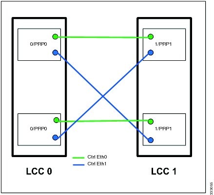
Before the additional LCC can be added to the CRS Back-to-Back System, a control network must be established. The control network allows two LCCs in the CRS Back-to-Back System to communicate with each other. The control function is performed by the PRPs.
This figure shows how the control Ethernet ports of PRPs are interconnected.
What to Do Next
Once the control network is connected, add the additional LCC to the CRS Back-to-Back System.
Adding an LCC to a CRS Back-to-Back System
This section describes how to add an LCC to a CRS Back-to-Back System.
Prerequisites
Software Requirements
- Cisco IOS XR Software Release 5.1.1 or later release
- ROMMON 2.08 or later version
- Serial number of new LCC (can be found on front of chassis)
Hardware Requirements
- The additional LCC.
- The control network must be operational and connected to all chassis.
- The power should be off for the LCC to be added.
- PRP route processor (if you are using CRS-16-RP-B on a single chassis)
Restrictions
None.
Summary Steps
Here are the basic steps to add the additional LCC to the CRS Back-to-Back System:
| Step 1 | Backup the exec and admin configs on LCC0. |
| Step 2 | Power ON the LCC (Rack 1) chassis. |
| Step 3 |
Interrupt the booting into drop the system (Active and Standby PRP) in ROMMON and verify the rack number (dumpplaneeeprom output ' 0x73rd byte) on the Active PRP.
|
| Step 4 |
If DRPs are present, bring down both CPUs (CPU0 and CPU1) to ROMMON while booting and type the following commands on both of the CPUs:.
|
| Step 5 | Configure the Active PRP using the following command, which associates LCC 1 serial numbers with the rack number: dsc serial rack serial number rack 1. |
| Step 6 | Configure Rack 1 in fabric rack install-mode using the following command: controllers fabric rack 1 install-mode. |
| Step 7 |
Connect the B2B fabric cables for all fabric planes.
|
| Step 8 | Boot the LCC Rack 1 by reset from the ROMMON prompt. |
| Step 9 | Verify that IOS XR RUN appears on the PRP faceplates. |
| Step 10 | Verify that all of the eight planes are UP/UP and the plane mode is B2B. Execute the following show command on dSC: show controllers fabric plane all detail. The plane state should be UP/UP and the plane mode should be B2B. |
| Step 11 | Check the rack status using the following command: do show controllers fabric rack-status all detail. |
| Step 12 | Remove the fabric install mode for Rack 1. Execute the following command: no controller fabric rack 1 install-mode. |
| Step 13 | Verify the status of all racks using the following command: show controllers fabric rack all. The plane state and mode for all of the eight planes should be the same as described in Step10. |
Detailed Steps
| Command or Action | Purpose | |
|---|---|---|
| Step 1 |
admin Example: RP/0/RP1/CPU0:router# admin |
Places the router in administration EXEC mode.
|
| Step 2 | configure Example: RP/0/RP1/CPU0:router(admin)#configure |
Places the router in administration configuration mode. |
| Step 3 |
From the ROMMON prompt, enter the following commands. Example: unset BOOT unset RACK_NUM unset BOOT_WITH_B2B_TAIKO set BOOT_WITH_B2B_TAIKO=1 unset TFTP_FILE unset TURBOBOOT confreg 0x0 sync reset |
From the console of the PRP in the new system, send the break (cntl+c) to disrupt the boot sequence. This places you at the rommon prompt. From here, issue the set command. This shows the current variables set on the PRP. If the variables listed are present, unset them as shown. Make sure to use sync at the end to save the changes. |
| Step 4 |
dsc serial serialNumber rack 1 Example: RP/0/RP1/CPU0:router(admin-config)# dsc serial TBA08440024 rack 1 |
Configures the additional LCC as Rack 1 in the multishelf system.
|
| Step 5 |
controllers fabric rack 1 install-mode Example: RP/0/RP1/CPU0:router(admin-config)# controllers fabric rack 1 install-mode |
Modifies the target configuration to change the Rack 1 configuration to installation mode. |
| Step 6 |
commit Example: RP/0/RP1/CPU0:router(admin-config)# commit |
Commits the target configuration to the router running configuration. |
| Step 7 | Apply power to the new LCC (Rack 1). |
Starts up the second LCC (Rack 1). |
| Step 8 | Interconnects the fabric cards between two LCCs. |
Connect all fabric cables that connect the fabric planes in the new LCC to the additional LCCs. |
| Step 9 |
From the ROMMON prompt, enter the following commands. Example: confreg 0x2 sync reset |
Boots the LCC Rack 1 by reset from the ROMMON prompt. Sets the config register to 0x2 and enables boot. |
| Step 10 | show platform Example: RP/0/RP1/CPU0:router(admin)# show platform Example: |
Displays the status of all LCC modules.
|
| Step 11 | show controllers fabric bundle 1/smslotNumber/sp/bundle port
connection Example: RP/0/RP1/CPU0:router(admin)#show controllers fabric bundle 1/sm1/sp/1 connection |
Shows whether the fabric connectivity between two LCCs has been successful. The bundle port value ranges from 0 to 2. In the case of wrong cabling, the CLI shows the following message: Actual connection data: Please check bundle connection, they appear to be swapped with another bundle. |
| Step 12 |
do show controllers fabric plane all detail Example: RP/0/RP1/CPU0:router(admin-config)# show controllers fabric plane all detail |
Displays the status of all planes. Wait for the plane to come up before you continue. |
| Step 13 | show controllers fabric fsdb-pla rack all Example: RP/0/RP1/CPU0:router(admin-config)# show controllers fabric fsdb-pla rack all |
Displays fabric plane availability for every destination in the system. |
| Step 14 | do show controllers fabric rack-status all detail Example: RP/0/RP1/CPU0:router(admin-config)# do show controllers fabric rack-status all detail |
Displays the status of all racks and additional information for racks in installation mode.
|
| Step 15 | do show controllers fabric fabric-backpressure summary Example: RP/0/RP1/CPU0:router(admin-config)# do show controllers fabric fabric-backpressure summary |
Displays the backpressure status for all racks.
|
| Step 16 | no controllers fabric rack 1 install-mode Example: RP/0/RP1/CPU0:router(admin-config)# no controllers fabric rack 1 install-mode |
Modifies the target configuration to change the Rack 1 configuration to normal mode. |
| Step 17 | commit Example: RP/0/RP1/CPU0:router(admin-config)# commit |
Commits the target configuration to the router running configuration. |
| Step 18 | do show controllers rack-status all detail Example: RP/0/RP1/CPU0:router(admin-config)# do show controllers rack-status all detail |
Displays the status of all racks in the system.
|
| Step 19 | do show controllers fabric plane all detail Example: RP/0/RP1/CPU0:router(admin-config)# do show controllers fabric plane all detail |
Displays the status of all planes.
|
Tips and Troubleshooting
- Make sure to use the correct B2B fabric/fiber cables.
- Before the Rack 1 install mode is removed, there will be constant Diag failure because the IngressQ bring up is halted. Online messages similar to the following may appear:
RP/0/RP1/CPU0:Jan 17 11:38:41.635 : online_diag_rp[338]: %DIAG-XR_DIAG-3-ERROR : (M) Fabric Ping Failure, 2 of 5 nodes failed(L): 1/RP0/CPU0, 1/RP1/CPU0
RP/0/RP1/CPU0:Jan 17 11:38:55.934 : online_diag_rp[338]: %DIAG-XR_DIAG-3-ERROR : (U) Fabric Ping Failure - destination node (Level 2) in 1/RP0/CPU0
RP/0/RP1/CPU0:Jan 17 11:39:05.498 : online_diag_rp[338]: %DIAG-XR_DIAG-3-ERROR : (UM) FIM: multi-nodes failure detected
Technical Assistance
|
Description |
Link |
|---|---|
|
The Cisco Technical Support website contains thousands of pages of searchable technical content, including links to products, technologies, solutions, technical tips, and tools. Registered Cisco.com users can log in from this page to access even more content. |
 Feedback